Page 25 of 99

62B-25
MR-413-X44-62B000$414_eng.mif
V1
62B
CLIMATE CONTROL
Fault finding - Interpretation of faults
DF001
PRESENT
OR
STOREDCOMPUTER
1. DEF: Internal electronic fault
NOTESConditions for running fault finding on a present or stored fault:
Apply this fault finding procedure if the fault reappears as present or stored after the
ignition is switched of f and on again.
Switch off the ignition and wait for the immobiliser warning light (Power-latch) to come one,
–Switch on the ignition again.
–Start the engine and switch on the air conditioning.
If the fault recurs, contact the Techline.
If the fault does not reappear: leave the climate control switched on and select various ventilation and air
distribution settings to check that the system is operating correctly.
–Check that no fault is displayed.
If the fault is still present, contact the Techline.
AFTER REPAIRFollow the instructions to confirm repair.
If the computer was replaced (at the request of the Techline), reconfigure the
computer (see Configurations and programming).
Deal with any other faults.
CLIM_V44_DF001
Vdiag No.: 44
MR-413-X44-62B000$414_eng.mif
Page 26 of 99

62B-26
MR-413-X44-62B000$414_eng.mif
V1
CLIMATE CONTROL
Fault finding - Interpretation of faults
Vdiag No.: 44
62B
DF007
PRESENT
OR
STOREDINTERIOR TEMPERATURE SENSOR CIRCUIT
CC.0 : Short circuit to earth
CO.1 : Short circuit or open circuit to + 12 V
NOTESConditions for running fault finding on a present or stored fault:
Apply this fault finding procedure if the fault reappears as present or stored after the
ignition is switched on and air conditioning activation is requested with the engine
running.
Special notes:
The interior temperature sensor is located at the top of the roof in the unit under the
rear view mirror.
Use the Wiring Diagram Technical Note for the New Twingo.
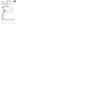
Check the connection and condition (possible wiring damage) of the connector of component 1872.
If the connector is faulty (see Technical Note 6015A, Repairing electrical wiring, Wiring: Precautions for the
repair), repair the connector, otherwise replace the wiring.
With connector A of component 419 and connector of union R301 disconnected, check the insulation and
continuity of the following connections between components R301 (dashboard/interior lights intermediate union)
and 419.
●connection 38JN
●connection 38GZ
If the connection or connections are faulty (see Technical Note 6015A, Repairing electrical wiring, Wiring:
Precautions for repair), repair the wiring, otherwise replace it.
With the connector of component 1872 disconnected, check the insulation and continuity of the following
connections between components R301 (dashboard/interior lights intermediate union) and 1872.
●connection 38JN
●connection 38GZ
If the connection or connections are faulty (see Technical Note 6015A, Repairing electrical wiring, Wiring:
Precautions for repair), repair the wiring, otherwise replace it.
Check the insulation of connections 38JN and 38GZ of component 1872.
If the connection or connections are faulty and there is a repair procedure (see Technical Note 6015A, Electrical
wiring repair, Wiring: Precautions for repair), repair the wiring, otherwise replace it.
Check the resistance of component 1872 between connections 38JN and 38GZ.
Replace the sensor if the resistance is not 10 kΩΩ Ω Ω
± 500 ΩΩ Ω Ω
at 25 ˚C. For more details, consult the electrical
specifications of the sensor according to the temperature (see Help).
If the fault is still present, contact the Techline.
AFTER REPAIRClear the stored faults.
Follow the instructions to confirm repair.
Deal with any other faults.
CLIM_V44_DF007
Page 27 of 99

62B-27
MR-413-X44-62B000$414_eng.mif
V1
CLIMATE CONTROL
Fault finding - Interpretation of faults
Vdiag No.: 44
62B
DF010
PRESENT
OR
STOREDMIXING MOTOR CIRCUIT
CO.0 : Open circuit or short circuit to earth
CC.1 : Short circuit to + 12 V
NOTESConditions for running fault finding on a present or stored fault:
The fault is declared present when the temperature control is activated (minimum or
maximum temperature request and air conditioning control panel on).
Special notes:
Wait 1 minute after repairing the fault so that the climate control computer can control
the mixer motor. To avoid having to wait for 1 minute, switch the ignition off and then
back on again.
There is no specific programming operation for the mixing motor, however, after it has
been replaced, the motor needs to program its limits (minimum and maximum).
Use the Wiring Diagram Technical Note for the New Twingo.
Check the connection and condition of the connector of component 420.
If the connector is faulty (see Technical Note 6015A, Repairing electrical wiring, Wiring: Precautions for the
repair), repair the connector, otherwise replace the wiring.
With connector B of component 419 disconnected, check the insulation and continuity of the following
connections between components 419 and 420:
●connection 38LC
●connection 38LD
●connection 38LG
●connection 38LH
If the connection or connections are faulty (see Technical Note 6015A, Repairing electrical wiring, Wiring:
Precautions for repair), repair the wiring, otherwise replace it.
Connector of component 1115 disconnected,
Check the insulation and continuity of connection S between components 419 and 420.
If the connection or connections are faulty (see Technical Note 6015A, Repairing electrical wiring, Wiring:
Precautions for repair), repair the wiring, otherwise replace it.
Connector of component 419 connected and ignition on,
●Check for 12 V supply on connection S of component 420 in relation to earth NAM.
If the connection is faulty (see Technical Note 6015A, Repairing electrical wiring, Wiring: Precautions for the
repair), repair the wiring, otherwise replace the wiring.
If the supply is not present and if no faulty connections are detected during the continuity checks, contact your
Techline.
AFTER REPAIRClear the stored faults.
Follow the instructions to confirm repair.
If the motor has been replaced (see Configuration and programming).
Deal with any other faults.
CLIM_V44_DF010
Page 28 of 99

62B-28
MR-413-X44-62B000$414_eng.mif
V1
CLIMATE CONTROL
Fault finding - Interpretation of faults
Vdiag No.: 44
62B
DF010
CONTINUED
With the connector disconnected, measure the resistance value of the mixing motor:
Check the resistance of component 420 between the following connections:
●connections S and 38LG,
●connections S and 38LC,
●connections S and 38LH,
●connections S and 38LD.
If the connection or connections are faulty (see Technical Note 6015A, Repairing electrical wiring, Wiring:
Precautions for repair), repair the wiring, otherwise replace it.
The results of the four checks should be 100 ΩΩ Ω Ω
±± ± ±
5 ΩΩ Ω Ω
at 20 ˚C, replace the mixing motor if this is not the case.
If the fault is still present, remove the mixing motor but leave it electrically connected and send a motor command
from the temperature buttons on the control panel: switch the temperature setting to maximum 27 ˚C (a value
of 100 %), then switch the temperature setting to minimum 15 ˚C (a value of 0 %), the motor must change from
one direction to the other. If the connections are correct but the motor does not switch during the commands:
replace the mixing motor.
AFTER REPAIRClear the stored faults.
Follow the instructions to confirm repair.
If the motor has been replaced (see Configuration and programming).
Deal with any other faults.
Page 29 of 99

62B-29
MR-413-X44-62B000$414_eng.mif
V1
CLIMATE CONTROL
Fault finding - Interpretation of faults
Vdiag No.: 44
62B
DF012
PRESENT
OR
STOREDDISTRIBUTION MOTOR CIRCUIT
CO.0 : Open circuit or short circuit to earth
CC.1 : Short circuit to + 12 V
NOTESConditions for running fault finding on a present or stored fault:
The fault is declared present with the air conditioning control panel on and the
distribution control activated (de-icing, ventilation, footwells, etc.).
Special notes:
Wait 1 minute after repairing the fault so that the climate control computer can control
the distribution motor. To avoid having to wait for 1 minute, switch the ignition off and
then back on again.
There is no specific programming operation for the distribution motor, however, after it
has been replaced, the motor needs to program its limits (minimum and maximum).
Use the Wiring Diagram Technical Note for the New Twingo.
Check the connection and condition of the connector of component 1115.
If the connector is faulty (see Technical Note 6015A, Repairing electrical wiring, Wiring: Precautions for the
repair), repair the connector, otherwise replace the wiring.
With connector of component 419 disconnected, check the insulation and continuity of the following
connections between components 419 and 1115:
●connection 38KY
●connection 38KZ
●connection 38LA
●connection 38LB
If the connection or connections are faulty (see Technical Note 6015A, Repairing electrical wiring, Wiring:
Precautions for repair), repair the wiring, otherwise replace it.
With the connector of component 420 disconnected, check the insulation and continuity of connection S
between components 419 and 1115.
If the connection or connections are faulty (see Technical Note 6015A, Repairing electrical wiring, Wiring:
Precautions for repair), repair the wiring, otherwise replace it.
Connector of component 419 connected and ignition on (air conditioning control panel on).
Check for 12 V supply on connection S of component 1115 in relation to earth NAM.
If the connection is faulty (see Technical Note 6015A, Repairing electrical wiring, Wiring: Precautions for the
repair), repair the wiring, otherwise replace the wiring.
If the supply is not present and if no faulty connections are detected during the continuity checks, contact your
Techline.
AFTER REPAIRClear the stored faults.
Follow the instructions to confirm repair.
If the motor has been replaced (see Configuration and programming).
Deal with any other faults.
CLIM_V44_DF012
Page 30 of 99

62B-30
MR-413-X44-62B000$414_eng.mif
V1
CLIMATE CONTROL
Fault finding - Interpretation of faults
Vdiag No.: 44
62B
DF012
CONTINUED
With the connector disconnected, measure the resistance value of component 1115 between the following
connections:
●connections S and 38KY,
●connections S and 38LA,
●connections S and 38LB,
●connections S and 38KZ.
If the connection or connections are faulty (see Technical Note 6015A, Repairing electrical wiring, Wiring:
Precautions for repair), repair the wiring, otherwise replace it.
The results of the four checks should be 100 ΩΩ Ω Ω
± 5
ΩΩ Ω Ω
at 20 ˚C, replace the distribution motor if this is not the case.
If the fault is still present, remove the distribution motor but leave it electrically connected, send a motor command
from the distribution buttons on the control panel: switch the distribution setting to demisting (a value of 100 %),
then switch the distribution setting to air vent (a value of 0 %), the motor must change from one direction to the
other. If the connections tested earlier match but the motor does not switch during the commands, replace the
distribution motor.
If the commands have been executed correctly, check that the distribution motor flap is not blocked by trying to
move the gears. Repair if necessary.
If the fault is still present, contact the Techline.
AFTER REPAIRClear the stored faults.
Follow the instructions to confirm repair.
If the motor has been replaced (see Configuration and programming).
Deal with any other faults.
Page 31 of 99

62B-31
MR-413-X44-62B000$414_eng.mif
V1
CLIMATE CONTROL
Fault finding - Interpretation of faults
Vdiag No.: 44
62B
DF021
PRESENT
OR
STORED RECIRCULATION MOTOR CIRCUIT
CO : Open circuit
CC.0 : Short circuit to earth
CC.1 : Short circuit to + 12 V
NOTESConditions for running fault finding on a present or stored fault:
The fault is declared present with the air conditioning panel on and the recirculation
control activated (recirculation selected for flap closed or exterior air selected for flap
open).
Special notes:
After repairing the fault (when the fault switches from present to stored), wait for
1 minute before the climate control computer is able to control the distribution motor.
To avoid having to wait for 1 minute, switch the ignition off and then back on again.
In extreme temperatures (above 35 ˚C) and when the climate control is switched on,
the recirculation flap sets itself to the recirculation position in order to correct the
passenger compartment temperature more quickly.
Use the Wiring Diagram Technical Note for the New Twingo.
Check the condition and connection of the connector of component 475.
If the connector is faulty (see Technical Note 6015A, Repairing electrical wiring, Wiring: Precautions for the
repair), repair the connector, otherwise replace the wiring.
With connector B of component 419 disconnected, check the insulation and continuity of the following
connections between components 419 and 475:
●connection 38JA
●connection 38JB
If the connection or connections are faulty (see Technical Note 6015A, Repairing electrical wiring, Wiring:
Precautions for repair), repair the wiring, otherwise replace it.
Check the resistance of component 475 between connections 38JA and 38JB.
If the connection or connections are faulty (see Technical Note 6015A, Repairing electrical wiring, Wiring:
Precautions for repair), repair the wiring, otherwise replace it.
Replace the motor if the resistance is not: 35 ΩΩ Ω Ω
± 5 ΩΩ Ω Ω
at 20 ˚C.
If the fault is still present, contact the Techline.
AFTER REPAIRClear the stored faults.
Follow the instructions to confirm repair.
If the motor has been replaced (see Configuration and programming).
Deal with any other faults.
CLIM_V44_DF021
Page 32 of 99

62B-32
MR-413-X44-62B000$460_eng.mif
V1
62B
CLIMATE CONTROL
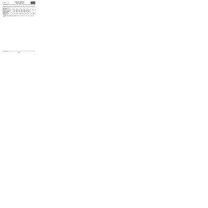
Fault finding - Conformity check
SUB-FUNCTION: PASSENGER COMPARTMENT VENTILATION
NOTESOnly carry out this conformity check after a complete check with the diagnostic tool
(fault reading and configuration checks).
Application conditions: engine stopped with ignition on (12 V APC), AIR
CONDITIONING OFF (air conditioning compressor not activated).
Note:
–Read the parameters when the vehicle is cold (in the morning) to check the
conformity of the temperature parameters (without thermometer). The two
temperatures should be practically the same (as should the coolant temperature
given by the injection system).
–The invalid values given in this check correspond to the value sent by the diagnostic
tool (substitute value) when the sensor in question is faulty. A sensor fault can be
detected when these invalid values are displayed (this is an important point for
sensors on which fault finding cannot be performed, e.g. exterior temperature
sensor).
Delayed illumination of the exterior temperature sensor LCD indicates that an invalid
value has been received concerning the exterior temperature sensor.
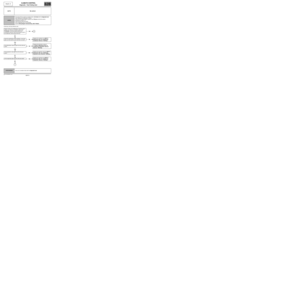
FunctionParameter or Status
checked or ActionDisplay and Notes Fault finding
Passenger
compartment
blowerET141:Passenger
compartment
blowerRUNNING
or
STOPPED
After a user requestIn the event of a fault, refer to the
interpretation of this status.
PR019:Passenger
compartment
fan PWM settingSpeed 0 = 0 %
Speed 8 = 100 %
Note:
The PWM signal is a
modulated control
voltage used to control
the air conditioning
blower power module.If there is a fault or for more
information (to find the
intermediate speed
percentages), refer to the
interpretation of this
parameter.
Note:
If the parameter varies correctly,
but the passenger compartment
blower unit does not operate:
consult ALP 5 "Air flow fault"
Air flapsPR012:Mixing flap
positionFrom 0 % (“Maximum
cold” position: 15 ˚C)
to 100 % (“Maximum
hot” position: 27 ˚C).In the event of a fault, see the
interpretation of this
parameter.
ET062:Recirculation
flap positionOPEN if the flap is in the
external air position.
CLOSED if the flap is in
the recirculation
position.In the event of a fault, refer to the
interpretation of this status.
PR011:Distribution flap
positionFrom 0 % (Air vent
position)
to 100 % (De-icing
position)In the event of a fault, see the
interpretation of this
parameter.
CLIM_V44_CCONF
Vdiag No.: 44
MR-413-X44-62B000$460_eng.mif