Page 384 of 652

13B-23
DIESEL INJECTION
High pressure pump: Removal - Refitting
K9K
13B
REFITTING
I - REFITTING PREPARATION OPERATION
a
aparts always to be replaced: Injection pump
sprocket nut
aparts always to be replaced: Front sub-frame
bolt
II - REFITTING OPERATION FOR PART
CONCERNED
aCheck that there is an indexing pin on the high pres-
sure pump shaft.
aPosition the high pressure pump on the cylinder
head whilst inserting it in its pulley.aFit the air filter unit bracket.
aFit the high pressure pump bolts on the cylinder
head, without tightening them, until contact is made.
aTighten to torque and in order the high pressure
pump bolts on the cylinder head (23 N.m).
aRefit the high pressure pump pulley, holding the high
pressure pump pulley with a 32 mm spanner.
aTorque tighten the high pressure pump pulley nut
(70 N.m) while holding the high pressure pump pul-
ley using a 32 mm spanner.
aCheck that the timing belt is correctly positioned and
in good condition.
aRemove the (Mot. 1606) from the cylinder head.
III - FINAL OPERATION
aRefit the suspended mounting on the cylinder head.
aTorque tighten the cylinder head suspended
mounting bolts (25 N.m). WARNING
Do not remove the blanking plugs from each
component until the last moment.
Also, do not remove the components from their
packaging until they are to be fitted to the vehi-
cle.
Note:
Check that the high pressure pump shaft is cor-
rectly orientated in relation to the pulley.
102085
Page 388 of 652

13B-27
DIESEL INJECTION
Flow actuator: Removal - Refitting
K9K
13B
aClean the diesel pipe unions on the high pressure
pump (see 13B, Diesel injection, Diesel injection:
Precautions for the repair, page 13B-1) .
aUnclip the fuel supply pipes at (2) .
aDisconnect the high pressure pump from:
-the diesel supply pipe (3) ,
-the diesel return pipe (4) to the diesel filter.
aRemove the high pressure pump pipes.aUnclip the neck at (5) .
aRemove the neck wiring harness.
aRemove:
-the neck nut (6) ,
-the neck.
aClean the high pressure pipe unions (7) between the
rail and injector number 4 (see 13B, Diesel injec-
tion, Diesel injection: Precautions for the repair,
page 13B-1) .
121423
WARNING
To avoid any corrosion or damage, protect the
areas on which fuel is likely to run.
WARNING
To prevent impurities from entering the circuit,
plugs must be fitted to the openings of all the fuel
circuit components exposed to the open air.121419
121418
WARNING
To avoid any corrosion or damage, protect the
areas on which fuel is likely to r un.
Page 397 of 652
13B-36
DIESEL INJECTION
High pressure pipe between pump and rail: Removal - Refitting
K9K
13B
aClean the diesel pipe unions on the high pressure
pump (see 13B, Diesel injection, Diesel injection:
Precautions for the repair, page 13B-1) .
aDisconnect the high pressure pump from:
-the diesel supply pipe (2) ,
-the diesel return pipe (3) to the diesel filter.
aFit suitable blanking plugs on:
-the high pressure pump,
-the high-pressure pipes.aUnclip the neck at (4) .
aRemove the neck wiring harness.
aRemove:
-the neck nut (5) ,
-the neck.
121423
WARNING
To avoid any corrosion or damage, protect the
areas on which fuel is likely to run.121419
Page 401 of 652
13B-40
DIESEL INJECTION
High pressure pipe between rail and injector: Removal - Refitting
K9K
13B
aClean the diesel pipe unions on the high pressure
pump (see 13B, Diesel injection, Diesel injection:
Precautions for the repair, page 13B-1) .
aDisconnect from the high pressure pump:
-the diesel supply pipe (2) ,
-the diesel return pipe (3) to the diesel filter.aUnclip the neck at (4) .
aRemove the neck wiring harness.
aRemove:
-the neck nut (5) ,
-the neck.
121423
WARNING
To avoid any corrosion or damage, protect the
areas on which fuel is likely to run.
WARNING
To prevent impurities from entering the circuit,
plugs must be fitted to the openings of all the fuel
circuit components exposed to the open air.121419
Page 406 of 652
13B-45
DIESEL INJECTION
Injector rail: Removal - Refitting
K9K
13B
aClean the fuel pipe unions on the high pressure
pump (see 13B, Diesel injection, Diesel injection:
Precautions for the repair, page 13B-1) .
a
aDisconnect the high pressure pump from:
-the fuel supply pipe (10) ,
-the fuel return pipe (11) to the fuel filter.
aInsert the blanking plugs.aClean the high pressure pipe unions (12) between
the pump and the rail (see 13B, Diesel injection,
Diesel injection: Precautions for the repair, page
13B-1) .
a
aRemove the high pressure pipe (12) between the
pump and the injection rail and discard it.
aInsert the blanking plugs.
121423
WARNING
To avoid any corrosion or damage, protect the
areas on which fuel is likely to run.127901
WARNING
To avoid any corrosion or damage, protect the
areas on which fuel is likely to r un.
Page 419 of 652

14A-1
ANTIPOLLUTION
Oil vapour rebreathing circuit: Descriptions
K9K
14A
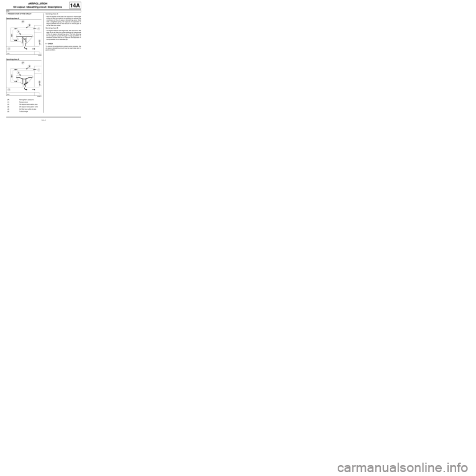
I - PRESENTATION OF THE CIRCUIT
Operating phase A
Operating phase BOperating phase A :
-with the engine at low load, the vacuum in the air pipe
at the air filter box outlet is not sufficient to activate the
membrane of the oil vapour rebreathing valve, fitted
with a weighted spring. Oil vapours are aspirated in
large quantities due to the vacuum in the air pipe at
the air filter box outlet.
Operating phase B :
-At engine medium and high load, the vacuum in the
pipe at the air filter box outlet attracts the membrane
of the oil vapour rebreathing valve. The hole allowing
the oil vapours to pass through in large quantities is
therefore closed and the oil vapours are aspirated in
low quantities via a calibrated jet.
II - CHECK
To ensure the antipollution system works properly, the
oil vapour rebreathing circuit must be kept clean and in
good condition.
20965
20965-1
(P) Atmospher ic pressure
(1) Rocker cover
(2) Oil vapour recirculation pipe
(3) Oil vapour recirculation valve
(4) Air filter box outlet air pipe
(5) Turbocharger
Page 422 of 652

14A-4
ANTIPOLLUTION
Fuel vapour absorber: Removal - Refitting
D4F or D7F or K4M, and TECHNICAL REG: GERMANY or TECHNICAL REG: AUSTRIA or TECHNICAL REG:
BALKANS or TECHNICAL-LEGISLATIVE BELGIUM or TECHNICAL REG: BOSNIA or TECHNICAL REG:
CYPRUS-MALTA or CZECH REP AND SLOVAKIA or TECHNICAL REG: DENMARK or TECHNICAL REG: DOM
(FRENCH OVERSEAS SUBDIVISION) or TECHNICAL REG: SPAIN or TECHNICAL REG: FINLAND or
TECHNICAL REG: FRANCE or TECHNICAL REG: GREAT BRITAIN or TECHNICAL REG: GREECE or
TECHNICAL-LEGISLATIVE HOLLAND or TECHNICAL REG: HUNGARY or TECHNICAL REG: IRELAND or
TECHNICAL REG: ICELAND or TECHNICAL REG: ISRAEL or TECHNICAL REG: ITALY or TECHNICAL REG:
JAPAN or TECHNICAL REG: NORTH or TECHNICAL REG: NORWAY or TECHNICAL REG: POLAND or
TECHNICAL REG: PORTUGAL or TECHNICAL REG: SLOVENIA or TECHNICAL REG: SWEDEN or TECHNICAL
REG: SWITZERLAND or TECHNICAL REG: TOM (FRENCH OVERSEAS TERRITORIES)
14A
REMOVAL
I - REMOVAL PREPARATION OPERATION
aPosition the vehicle on a two-post lift (see Vehicle:
Towing and lifting) (02A, Lifting equipment).
aDisconnect the battery (see Battery: Removal - Re-
fitting) (80A, Battery).
II - REMOVAL OPERATION
aUnclip:
-the fuel filter on the fuel vapour absorber in the di-
rection of the arrow (1) ,
-the fuel vapour absorber in the direction of the ar-
row (2) . IMPORTANT
During this oper ation, be sure to:
-refrain from smoking or bringing red hot objects
close to the working area,
-be careful of fuel splashes when disconnecting the
union.
IMPORTANT
Wear goggles with side protectors for this opera-
tion.
IMPORTANT
Wear leaktight gloves (Nitrile type) for this opera-
tion.
WARNING
To avoid any corrosion or damage, protect the
areas on which fuel is likely to run.
WARNING
Keep the pipe unions away from contaminated
areas.
WARNING
To prevent impurities from entering the circuit, place
protective plugs on all fuel circuit components
exposed to the open air.
D4F or D7F
120513
Page 428 of 652

14A-10
ANTIPOLLUTION
Exhaust gas recirculation solenoid valve: Removal - Refitting
K9K
14A
PARTS AND CONSUMABLES FOR THE
REPAIR WORK
aConsumables (see Vehicle: Parts and consuma-
bles for the repair) (02A, Parts and consumables):
-ABRASIVE PAD,
-SURFACE CLEANER.
REMOVAL
I - REMOVAL PREPARATION OPERATION
aRemove:
-the engine cover,
-the air filter box (see 12A, Fuel mixture, Air filter
unit: Removal - Refitting, page 12A-13) .
II - OPERATION FOR REMOVAL OF PART
CONCERNED
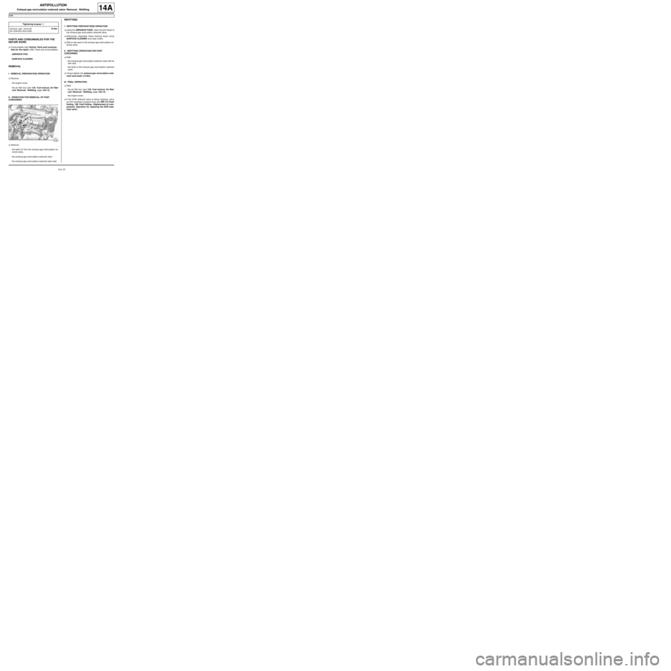
aRemove:
-the bolts (1) from the exhaust gas recirculation so-
lenoid valve,
-the exhaust gas recirculation solenoid valve,
-the exhaust gas recirculation solenoid valve seal.
REFITTING
I - REFITTING PREPARATIONS OPERATION
aUsing the ABRASIVE PADS, clean the joint faces of
the exhaust gas recirculation solenoid valve.
aAfterwards, degrease these bearing faces using
SURFACE CLEANER and clean cloths.
aRefit a new seal on the exhaust gas recirculation so-
lenoid valve.
II - REFITTING OPERATION FOR PART
CONCERNED
aRefit:
-the exhaust gas recirculation solenoid valve with its
new seal,
-the bolts to the exhaust gas recirculation solenoid
valve.
aTorque tighten the exhaust gas recirculation sole-
noid valve bolts (10 Nm).
III - FINAL OPERATION.
aRefit:
-the air filter box (see 12A, Fuel mixture, Air filter
unit: Removal - Refitting, page 12A-13) ,
-the engine cover.
aIf the EGR solenoid valve is being replaced, carry
out the necessary programming (see MR 413 Fault
finding, 13B, Fault finding - Replacement of com-
ponents, Operation for replacing the EGR sole-
noid valve). Tightening torquesm
exhaust gas recircula-
tion solenoid valve bolts10 Nm
121637