2009 RENAULT TWINGO air filter
[x] Cancel search: air filterPage 340 of 652

12B-15
TURBOCHARGING
Turbocharger oil pipe: Removal - Refitting
D4F, and 780 or 782
12B
aRefit:
-the upstream oxygen sensor (see 17B, Petrol in-
jection, Oxygen sensors: Removal - Refitting,
page 17B-13) ,
-the air filter box strut,
-the air filter box strut bolt,
-the air filter unit (see 12A, Fuel mixture, Air filter
unit: Removal - Refitting, page 12A-13) .
aConnect the battery (see Battery: Removal - Refit-
ting) (80A, Battery).
Page 341 of 652

12B-16
TURBOCHARGING
Turbocharger oil pipe: Removal - Refitting
C44, and K9K
12B
REMOVAL
I - REMOVAL PREPARATION OPERATION
aPosition the vehicle on a two-post lift (see Vehicle:
Towing and lifting) (02A, Lifting equipment).
aRemove the front engine cover.
aDisconnect the battery (see Battery: Removal - Re-
fitting) (80A, Battery).
1 - Turbocharger oil supply pipe
aRemove:
-the windscreen wiper arms (see Windscreen wip-
er arm: Removal - Refitting) (85A, Wiping -
Washing),
-the scuttle panel grille (see Scuttle panel grille:
Removal - Refitting) (56A, Exterior equipment),
-the scoop under the scuttle panel grille (see Scoop
under the scuttle panel grille: Removal - Refit-
ting) (56A, Exterior equipment),
-the air filter box (see 12A, Fuel mixture, Air filter
unit: Removal - Refitting, page 12A-13) ,
-the exhaust gas recirculation solenoid valve (see
14A, Antipollution, Exhaust gas recirculation
solenoid valve: Removal - Refitting, page 14A-
10) .
2 - turbocharger oil return pipe
aRemove the catalytic converter (see 19B, Exhaust,
Catalytic converter: Removal - Refitting, page
19B-12) .II - OPERATION FOR REMOVAL OF PART
CONCERNED
1 - Turbocharger oil supply pipe
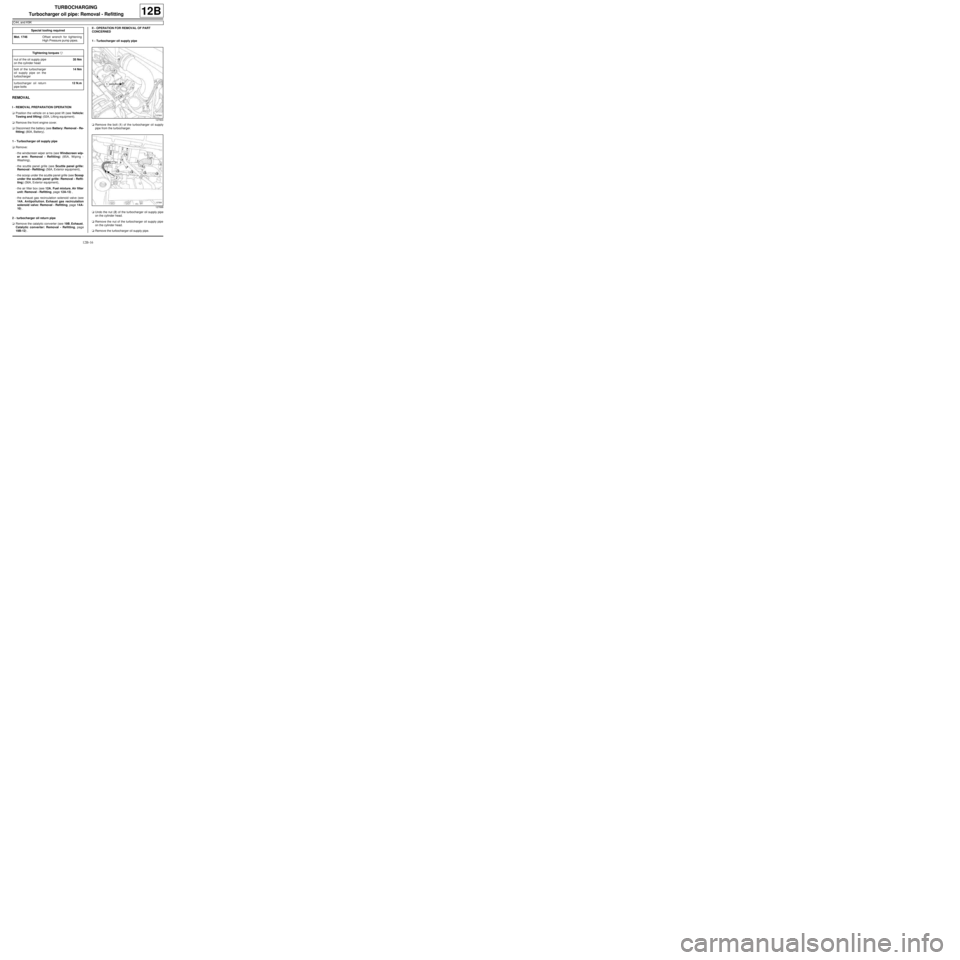
aRemove the bolt (1) of the turbocharger oil supply
pipe from the turbocharger.
aUndo the nut (2) of the turbocharger oil supply pipe
on the cylinder head.
aRemove the nut of the turbocharger oil supply pipe
on the cylinder head.
aRemove the turbocharger oil supply pipe. Special tooling required
Mot. 1746Offset wrench for tightening
High Pressure pump pipes.
Tightening torquesm
nut of the oil supply pipe
on the cylinder head35 Nm
bolt of the turbocharger
oil supply pipe on the
turbocharger14 Nm
turbocharger oil return
pipe bolts12 N.m
127900
127898
Page 342 of 652

12B-17
TURBOCHARGING
Turbocharger oil pipe: Removal - Refitting
C44, and K9K
12B
2 - Oil return pipe
aRemove the bolts (3) of the oil return pipe from the
turbocharger.
aIn the direction of the arrows, rotate the oil return
pipe of the turbocharger to facilitate its removal.
aRemove the turbocharger oil pipe from the cylinder
block.
REFITTING
I - REMOVAL PREPARATION OPERATION
aAlways replace:
-the turbocharger oil supply pipe,
-the flat seal of the oil return pip on the turbocharg-
er,
-the O-ring of the oil return pip on the turbocharger.
aLubricate the O-ring of the oil return pipe on the tur-
bocharger with engine oil.
II - REFITTING OPERATION FOR PART
CONCERNED
1 - Turbocharger oil supply pipe
aFit the turbocharger oil supply pipe.
aRefit:
-the turbocharger oil supply pipe nut on the cylinder
head,-the bolt of the turbocharger oil supply pipe onto the
turbocharger.
aTorque tighten:
-the nut of the oil supply pipe on the cylinder
head ( 35 Nm) using the (Mot. 1746),
-the bolt of the turbocharger oil supply pipe on
the turbocharger (14 Nm).
2 - turbocharger oil return pipe
aFit the oil return pipe on the cylinder block.
aRefit the turbocharger oil return pipe bolts.
aTorque tighten the turbocharger oil return pipe
bolts (12 N.m).
III - FINAL OPERATION.
1 - Turbocharger oil supply pipe
aRefit:
-the exhaust gas recirculation solenoid valve (see
14A, Antipollution, Exhaust gas recirculation
solenoid valve: Removal - Refitting, page 14A-
10) ,
-the air filter box (see 12A, Fuel mixture, Air filter
unit: Removal - Refitting, page 12A-13) ,
-the scoop under the scuttle panel grille (see Scoop
under the scuttle panel grille: Removal - Refit-
ting) (56A, Exterior equipment),
-the scuttle panel grille (see Scuttle panel grille:
Removal - Refitting) (56A, Exterior equipment),
-the windscreen wiper arms (see Windscreen wip-
er arm: Removal - Refitting) (85A, Wiping -
Washing).
aConnect the battery (see Battery: Removal - Refit-
ting) (80A, Battery).
2 - turbocharger oil return pipe
aRefit the catalytic converter (see 19B, Exhaust,
Catalytic converter: Removal - Refitting, page
19B-12) .
aConnect the battery (see Battery: Removal - Refit-
ting) (80A, Battery).
aRefit the engine cover.
127899
Page 347 of 652

13A-4
FUEL SUPPLY
Fuel filter: Removal - Refitting
K9K
13A
PARTS AND CONSUMABLES FOR THE
REPAIR WORK
aCONSUMABLES:
-cleaning cloths.
aMake sure you have a new diesel filter before open-
ing the fuel circuit.
REMOVAL
I - REMOVAL PREPARATION OPERATION
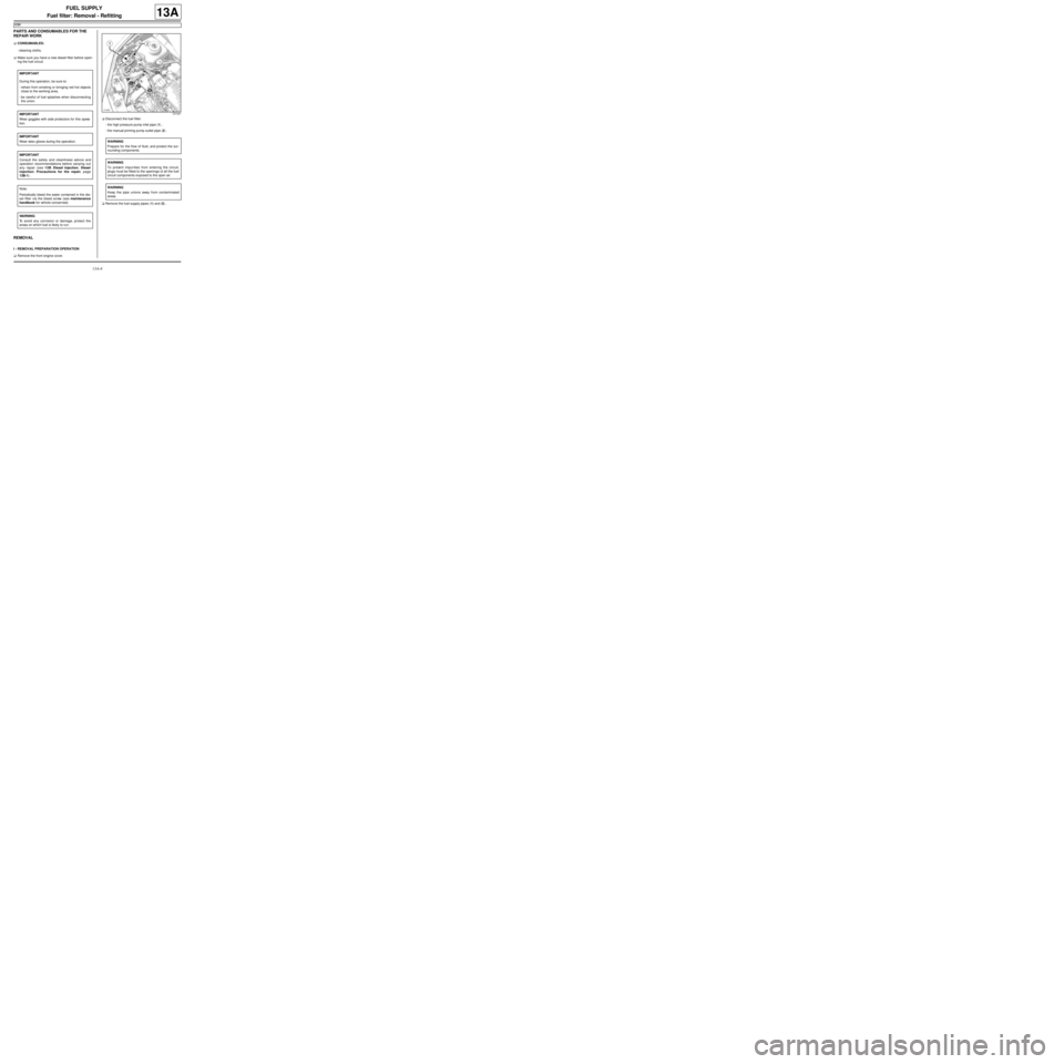
aRemove the front engine cover.aDisconnect the fuel filter:
-the high pressure pump inlet pipe (1) ,
-the manual priming pump outlet pipe (2) .
aRemove the fuel supply pipes (1) and (2) . IMPORTANT
During this operation, be sure to:
-refrain from smoking or bringing red hot objects
close to the working area,
-be careful of fuel splashes when disconnecting
the union.
IMPORTANT
Wear goggles with side protectors for this opera-
tion.
IMPORTANT
Wear latex gloves during the operation.
IMPORTANT
Consult the safety and cleanliness advice and
operation recommendations before carrying out
any repair (see 13B, Diesel injection, Diesel
injection: Precautions for the repair, page
13B-1) .
Note:
Periodically bleed the water contained in the die-
sel filter via the bleed screw (see maintenance
handbook for vehicle concerned).
WARNING
To avoid any corrosion or damage, protect the
areas on which fuel is likely to run.
121441
WARNING
Prepare for the flow of fluid, and protect the sur-
rounding components.
WARNING
To prevent impur ities from entering the circuit,
plugs must be fitted to the openings of all the fuel
circuit components exposed to the open air.
WARNING
Keep the pipe unions away from contaminated
areas.
Page 348 of 652

13A-5
FUEL SUPPLY
Fuel filter: Removal - Refitting
K9K
13A
II - OPERATION FOR REMOVAL OF PART
CONCERNED
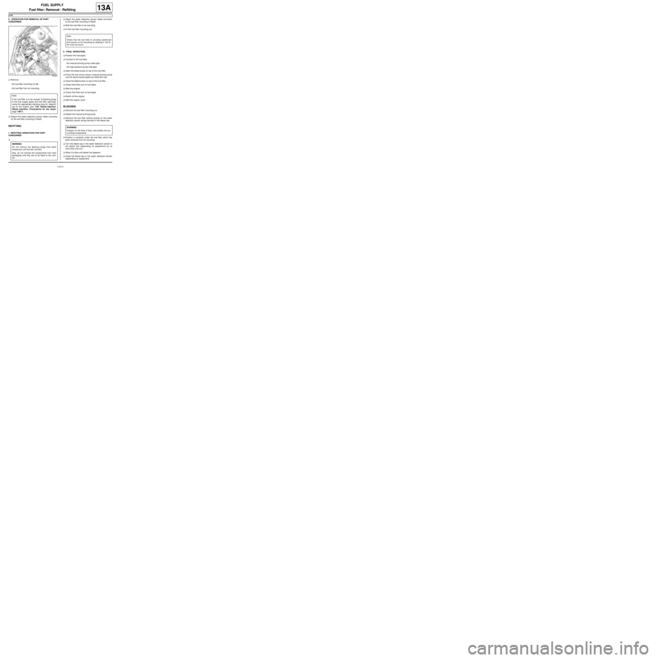
aRemove:
-the fuel filter mounting nut (3) ,
-the fuel filter from its mounting.
aDetach the water detection sensor offset connector
on the fuel filter mounting (if fitted).
REFITTING
I - REFITTING OPERATION FOR PART
CONCERNED
aaAttach the water detection sensor offset connector
to the fuel filter mounting (if fitted).
aRefit the fuel filter to its mounting.
aFit the fuel filter mounting nut.
II - FINAL OPERATION.
aPosition the fuel pipes.
aConnect to the fuel filter:
-the manual priming pump outlet pipe,
-the high pressure pump inlet pipe.
aOpen the bleed screw on top of the fuel filter.
aPrime the fuel circuit using a manual priming pump
until the disconnected pipes are filled with fuel.
aClose the bleed screw on top of the fuel filter.
aCheck that there are no fuel leaks.
aStart the engine.
aCheck that there are no fuel leaks.
aSwitch off the engine.
aRefit the engine cover.
BLEEDING
aRemove the fuel filter mounting nut.
aDetach the manual priming pump.
aRemove the fuel filter without pulling on the water
detection sensor wiring harness in the diesel fuel.
aPosition a container under the fuel filter which has
been removed from its mounting.
aTurn the bleed cap or the water detection sensor in
the diesel fuel (depending on equipment) by no
more than one turn.
aAllow it to flow until diesel fuel appears.
aClose the bleed cap or the water detection sensor
(depending on equipment).
121441
Note:
If the fuel filter is to be reused, fit blanking plugs
to the fuel supply pipes and fuel filter openings,
using the appropriate blanking plug kit, depend-
ing on the engine (see 13B, Diesel injection,
Diesel injection: Precautions for the repair,
page 13B-1) .
WARNING
Do not remove the blanking plugs from each
component until the last moment.
Also, do not remove the components from their
packaging until they are to be fitted to the vehi-
cle.
Note:
Chec k that the fuel filter is correctly positioned
and secure on its mounting by shaking it: the fil-
ter must not move.
WARNING
Prepare for the flow of fluid, and protect the sur-
rounding components.
Page 362 of 652

13B-1
DIESEL INJECTION
Diesel injection: Precautions for the repair
K9K
13B
I - RISKS RELATING TO CONTAMINATION
The high-pressure direct injection system is highly sen-
sitive to contamination. The risks caused by contami-
nation are:
-damage to or destruction of the high pressure injec-
tion system,
-a component seizing,
-a component not being properly sealed.
All After-Sales operations must be performed under
very clean conditions. Having carried out an operation
in good conditions means that no impurities (particles a
few microns in size) have penetrated the system during
dismantling.
The cleanliness principle must be applied from the filter
to the injectors.
What are the sources of contamination?
-metal or plastic swarf,
-paint,
-fibres:
•cardboard,
•brushes,
•paper,
•clothing,
•cloth,
-foreign bodies such as hair,
-ambient air,
-etc.
1 - Cleaning cloths
Use lint-free cleaning cloths (see Vehicle: Parts and
consumables for the repair) (04B, Consumables -
Products).
It is prohibited to use cloths or ordinary paper towels:
these produce lint and lose fibres, which then contami-
nate the fuel circuit.
Each cloth must only be used once.2 - Blanking plugs
The blanking plugs are used to cap the fuel circuit once
it is opened and to therefore prevent contaminants
from entering.
A set of blanking plugs should be used once only and
used plugs must be discarded after use: once used,
the plugs are soiled and cleaning them is not sufficient
to make them reusable.
Unused plugs must also be discarded and must not be
used when carrying out work on an injection system.
Part number for set of blanking plugs: (see Vehicle:
Parts and consumables for the repair) (04B, Con-
sumables - Products).
3 - Protective bags
Use hermetically-resealable plastic bags, using adhe-
sive tape, for example, to store components which will
be refitted and reused. Stored parts will therefore be
less subject to the risk of contamination.
These are single-use bags: after use they must be dis-
carded.
4 - Cleaning products
Two cleaning products can be used:
-an injector cleaner (see Vehicle: Parts and consum-
ables for the repair) (04B, Consumables - Products),
-an aerosol spray brake cleaner (see Vehicle: Parts
and consumables for the repair) (04B, Consum-
ables - Products).
To use the injector cleaner, be sure to have a clean
brush in good condition (the brush must not lose any
bristles) as well as a clean container which has no im-
purities in it. WARNING
Do not clean the engine with a high pressure
cleaner to prevent damaging the connections.
Note:
There is no specific set of blanking plugs for S9U
and S9W engines. In order to comply with the
cleanliness recommendations, use plugs that are
compatible with the blanking plug sets for F9Q,
G9U, G9T or ZD3 engines.
Note:
Use a new injector cleaner each time work is car-
ried out (a used cleaning agent will contain impuri-
ties).
Page 378 of 652

13B-17
DIESEL INJECTION
High pressure pump: Removal - Refitting
K9K
13B
a
Clean the union on the diesel fuel supply pipe high
pressure pump (see 13B, Diesel injection, Diesel
injection: Precautions for the repair, page 13B-1)
.
aUnclip:
-the fuel supply and return pipes at (2) ,
-the priming pump (3) .
aDisconnect the high pressure pump from:
-the diesel supply pipe (4) ,
-the diesel return pipe (5) to the diesel filter.
aInsert the blanking plugs.
aRemove the fuel supply pipes from the pump.
aRemove:
-the fuel filter (see 13A, Fuel supply, Fuel filter:
Removal - Refitting, page 13A-4) ,
-the fuel filter mounting bolts,
-the fuel filter holder,aUnclip the engine wiring channel at (6) .
aMove the engine wiring away from the engine wiring
channel.
aRemove:
-the nut (7) from the channel,
-the channel,
-the engine tie-bar (see 19D, Engine mounting,
Lower engine tie-bar: Removal - Refitting, page
19D-18) .
121423
WARNING
To avoid any corrosion or damage, protect the
areas on which fuel is likely to run.
WARNING
To prevent impurities from entering the circuit,
plugs must be fitted to the openings of all the fuel
circuit components exposed to the open air.
121419
Page 383 of 652

13B-22
DIESEL INJECTION
High pressure pump: Removal - Refitting
K9K
13B
aFit the (Mot. 1525) (20) with the (Mot. 1525-02) on
the high pressure pump pulley.
aScrew the (Mot. 1525) pushrod until it makes con-
tact with the high pressure pump shaft.
aCheck that the (Mot. 1525) pushrod is correctly ori-
entated and is pressing against the high pressure
pump shaft. adjust the tool if necessary.II - OPERATION FOR REMOVAL OF PART
CONCERNED
aRemove:
-the bolts (21) from the high pressure pump on the
cylinder head,
-the air filter unit bracket (22) .
aGradually screw the pushrod of the (Mot. 1525) until
the high pressure pump becomes detached.
aRemove the high pressure pump.
aRemove the (Mot. 1525) and (Mot. 1525-02) from
the high pressure pump pulley.
23169
Note:
If necessary, remove the spacer at the end push-
rod of the (Mot. 1525) to improve the positioning.
102085
Note:
Guide and suppor t the high pressure pump as it
is being removed using the (Mot. 1525).
Note:
If the high pressure pump is being reused, keep
it in a sealed bag during the removal operation.