Page 17 of 33

88B-17V3 MR-413-X44-88B000$060.mif
88B
MULTIPLEX NETWORK CONFIGURATION
For the
CAN Vehicle network:
The tool displays the UCH and/or Airbag configurations.
The Configuration screen consists of two tabs for displaying and modifying the:
–The first tab, Multiplex network configuration, indicates the multiplex network version and the list of computers
defined as present on the multiplex network.
–The second tab, Configuration of computers which support fault finding, indicates the relevant diagram
number, and the list of computers defined as supporting fault finding with the RENAULT tool.
First repair the computers containing the multiplex network configuration (Airbag and UCH) in order to
display the screen with the multiplex network configuration diagram for the vehicle on which fault finding is
being run.
For the
CAN Multimedia network:
The tool presents the configuration of the A2/A3 display.
The Configuration screen consists of two tabs for displaying and modifying the:
–The first tab, Multiplex network configuration, indicates the multiplex network version and the list of computers
defined as present on the multiplex network.
–The second tab, Configuration of computers which support fault finding, indicates the relevant diagram
number, and the list of computers defined as supporting fault finding with the RENAULT tool.
NOTESThe configuration is entered with the ignition on; apply the forced + after ignition
feed procedure (see Introduction).
It can be run from the multiplex network test results screens.
WARNING: the network version number is 1.
This is the diagram version which changes each time the multiplex network wiring is modified on this vehicle.
WARNING: the network version number is 1.
This is the diagram version which changes each time the multiplex network wiring is modified on this vehicle.
MULTIPLEXING
Fault finding – Configuration
Page 18 of 33
88B-18V3 MR-413-X44-88B000$060.mif
MULTIPLEXING
Fault finding – Configuration88B
First repair the computer containing the multiplex network configuration (A2/A3 display) in order to display
the screen with the multiplex network configuration diagram for the vehicle on which fault finding is being
run.
Here is the list of computers according to the radio equipment:
Radio R1-08:
–Radio R1-08
–A2 display
Radio R2-08:
–Radio R2-08
–A3 display
–Multimedia connection (C-box)
IMPORTANT
A computer connected to the multiplex network but not declared as being among the computers containing the
multiplex network configuration will not be checked in the multiplex network test.
Correct the configuration by declaring the missing computer as present in the computer or computers containing
the configuration.
Start the multiplex network test again after modifying the configuration.
Page 19 of 33

88B-19V3 MR-413-X44-88B000$060.mif
MULTIPLEXING
Fault finding – Configuration88B
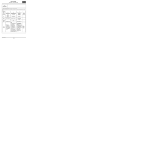
CAN Vehicle configuration screen
Make sure that the information displayed on the two tabs is correct.
The same configuration information for the two computers is essential for displaying the network topology.
Option: depending on equipment level
CAN Multimedia configuration screen Computer Multiplex network configurationConfiguration of computers that
can support fault finding
Injection (120) PRESENT YES
ABS/ESP (1094) PRESENT YES
Instrument panel (247) PRESENT YES
UCH (645) PRESENT YES
Airbag/pretensioners (756) PRESENT YES
Air conditioning (regulated) (419) PRESENT (option) YES (option)
Sequential gearbox (119) PRESENT (option) YES (option)
Power-assisted steering (502) ABSENT (option) YES (on K line) (option)
Rev counter (995) PRESENT (option) YES (option)
Parking distance control (1222) ABSENT YES (on K line)
A2/A3 display (653) PRESENT (option) YES (option)
Computer Multiplex network configurationConfiguration of computers that
can support fault finding
A2/A3 display (653) PRESENT YES
Radio R1-08 or R2-08 (261) PRESENT or ABSENT (option) YES or NO (option)
Page 20 of 33

88B-20
AFTER REPAIRRun the multiplex network test again using the diagnostic tool.
Clear the stored faults on all the computers connected to the network.
Deal with any other faults.
V3 MR-413-X44-88B000$070.mif
88B
MULTIPLEX NETWORK NOT OPERATIONAL
NOTESFirst check that the computer at the end of the faulty segment is properly powered
(earth, + battery, + accessories or + after ignition).
Always check the computer conformity.
Switch off the ignition.
Finding the fault
type
NOTESObtain a copy of the multiplex network diagram for the
vehicle.
(Diagnostic socket diagram).
Measure the resistance of component 225 between the following connections:
•Connection code 133B
•Connection code 133C
What is the value obtained?
0 ΩΩ Ω ΩThe two lines are in short circuit (see Introduction - Repair advice).
60 ΩΩ Ω Ω
± 10 ΩΩ Ω Ω
Check first that the computers storing the configuration (Airbag and UCH) are
correctly supplied:
–check for earth on connection NAP, and for +12 V supply on connection AP25 on
component 756.
–check for earth on connections MAM and NAM, and for +12 V supply on
connections AP7, AP43, BP3, BP6, BP15, BP19, BP49 on component 645.
BETWEEN 70 ΩΩ Ω Ω
AND 110 ΩΩ Ω ΩFor each connection 133B and 133C, check that there is no interference resistance
and then check that there is no short circuit to earth or to the + battery feed.
120 ΩΩ Ω Ω
± 10 ΩΩ Ω Ω
Open circuit on one or two lines.
Disconnect the airbag and check the multiplex connection between the diagnostic
socket and the airbag.
Is the multiplex connection correct?
MULTIPLEXING
Fault finding – Interpretation of faults
Page 21 of 33
88B-21
AFTER REPAIRRun the multiplex network test again using the diagnostic tool.
Clear the stored faults on all the computers connected to the network.
Deal with any other faults.
V3 MR-413-X44-88B000$070.mif
MULTIPLEXING
Fault finding – Interpretation of faults88B
MULTIPLEX NETWORK NOT OPERATIONAL (continued)
YES
Check that the resistance is approximately 120 Ω between the two network
connections on the airbag computer:
–If the resistance is not approximately 120 Ω, contact Techline.
–If the resistance is 120 Ω, check the continuity and absence of interference
resistance on the multiplex connection between the diagnostic socket and the UCH.
Repair if necessary.
Check that the resistance is approximately 120 Ω between the two network
connections on the UCH computer:
– If the resistance is not approximately 120 Ω, contact Techline.
NORepair the multiplex connection between the diagnostic socket and the airbag.
If the fault is still present, contact your Techline.
Page 22 of 33

88B-22
AFTER REPAIRRun the multiplex network test again using the diagnostic tool.
Clear the stored faults on all the computers connected to the network.
Deal with any other faults.
V3 MR-413-X44-88B000$070.mif
MULTIPLEXING
Fault finding – Interpretation of faults88B
FAULTY SEGMENT ON THE MULTIPLEX NETWORK
NOTESFirst check that the computer at the end of the faulty segment is properly powered
(earth, + battery, + accessories or + after ignition).
Always check the computer conformity.
IMPORTANT
It may be that the tool cannot exactly determine which segment(s) are faulty. It will then
suggest several segments that could be faulty. In this event, repair the segment closest
to the diagnostic socket.
Isolate the faulty segment by disconnecting both ends of the segment. Check the condition of the connectors.
Check the continuity and insulation of the CAN H and CAN L lines (connections 133B and 133C) between the two
connectors of the isolated segment.
Refer to the vehicle's multiplex network diagram for the allocation of tracks on the computers and connections.
Perform the necessary operations to check the continuity of the two lines (for example, replacing the wiring).
Make sure that the computer present in the vehicle is compatible and that the data it is producing is correct.
Reconnect the segment.
Carry out the multiplex network test again using the diagnostic tool.
Is the segment still declared faulty?
NOEnd of fault finding.
YESAre there other faulty segments?
NO
Repeat the multiplex network tests to ensure the continuity and insulation of the CAN
H and CAN L lines (connections 133B and 133C) between the end of the faulty
segment and the diagnostic socket.
YESApply the same procedure to each segment.
Page 23 of 33

88B-23
AFTER REPAIRRun the multiplex network test again using the diagnostic tool.
Clear the stored faults on all the computers connected to the network.
Deal with any other faults.
V3 MR-413-X44-88B000$070.mif
MULTIPLEXING
Fault finding – Interpretation of faults88B
FAULTY COMPUTER
Vehicle multiplex network
NOTESMake sure that the computers installed in the vehicle are the correct type and are
compatible with the vehicle.
Check that the computers are correctly supplied (earth, + battery feed,
+ accessories feed or + after ignition feed).
Make sure that the computer wake-up mode is in full working order on the vehicle and is properly assimilated
by the computers.
The wake-up mode is:
–Timed supply: UCH,
–+ accessories feed: Air conditioning, ABS/ESP.
–+ after ignition feed: Injection, Airbag/Pretensioners, Sequential gearbox, Instrument panel.
In + accessories feed these computers will not appear.
–Switch to computer fault finding mode.
Attempt to establish dialogue with computers.
No communication from computers to diagnostic tool: see ALP 1
No communication with the computer or computers not communicating with the diagnostic tool.
Check the connections to the computers and that there are no open circuits.
Repair if necessary.
Computers are not displaying all the information on their identifications:
Check in the Workshop Repair Manual or the World Vehicle Database that the computer is compatible
with the vehicle.
Check that the CLIP diagnostic tool update is recent enough to be able to deal with faults on the vehicle.
If no faults or open or short circuits have been detected after these checks, contact Techline.
Page 24 of 33

88B-24
AFTER REPAIRRun the multiplex network test again using the diagnostic tool.
Clear the stored faults on all the computers connected to the network.
Deal with any other faults.
V3 MR-413-X44-88B000$070.mif
MULTIPLEXING
Fault finding – Interpretation of faults88B
FAULTY COMPUTER (continued 1)
Multimedia multiplex network
NOTESSwitch off the vehicle ignition.
Measure the resistance of component 225 between the following Multimedia multiplex line connections:
–connection code 107X
–connection code 107W
What is the value of the resistance?
0 ΩΩ Ω ΩThe two lines are in short circuit (see Introduction - Repair advice).
60 ΩΩ Ω Ω
± 10 ΩΩ Ω Ω
For radio R1-08 and radio R2-08:
Check for earth on connection MA0, and for +12 V supply on connection BCP4 to the
radio 261.
Check for earth on connection NAM, and for +12 V supply on connection BCP4 and
BPT to the display 653.
For the Multimedia connection (C-box):
Check for earth on connection NAM, and for +12 V supply on connection BCP4 to the
Multimedia connection computer (C-box) 1959.
BETWEEN 70 ΩΩ Ω Ω
AND 110 ΩΩ Ω ΩFor each of Multimedia multiplex line connections 107X and 107W, check that there
is no interference resistance and then check that there is no short circuit to earth or to
the + battery feed.
120 ΩΩ Ω Ω
± 10 ΩΩ Ω Ω
Open circuit on one or both lines
For radio R1-08 and radio R2-08
Disconnect component 261 and check the multimedia multiplex connections 107X
and 107W between components 225 and 261.
For the Multimedia connection (C-box):
Disconnect component 1959 and check the multimedia multiplex connections
107X and 107W between components 225 and 1959.
Is the multiplex connection correct?


 in order to display
the scr")
