Page 9 of 33
88B-9V3 MR-413-X44-88B000$020.mif
MULTIPLEXING
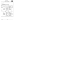
Fault finding – List and location of components88B
1222
995
261
645
756
502 120 119 10942251959653247
419
Page 10 of 33
88B-10V3 MR-413-X44-88B000$030.mif
MULTIPLEXING
Fault finding – Operating diagram88B
Operating diagram of the CAN Vehicle network
Number Description
119 Automatic gearbox
120 Injection computer
247 Instrument panel
419 Air conditioning
502 Power-assisted steering
645 UCH
653 Multimedia interface
756 Airbags
995 Electronic rev counter
1094 ABS
1222 Parking distance control
OBD Diagnostic socket
E134 Splice
R107 Dashboard - front of engine connection
E133 Splice
120
010
11 123
5
6
7 89 OBDE134
E133 R107
645 1094119
419
995
247
653
1222 502 756
MULTIPLEXING
Fault finding – Operating diagram
Page 11 of 33
88B-11V3 MR-413-X44-88B000$030.mif
MULTIPLEXING
Fault finding – Operating diagram88B
Operating diagram of the CAN Multimedia network
Number Description
E1 Splice
OBD Diagnostic socket
653 Multimedia interface
261 Radio
1959 Multimedia connection
OBD653
0
1
23
E1
2611959
Page 12 of 33
88B-12V3 MR-413-X44-88B000$040.mif
88B
To improve the performances of vehicles, more computers are needed to share more information in order to achieve
optimal operation.
With multiplexing, numerous signals can be sent from one computer to several others via a single electrical
connection.
Solution without multiplexing
Example: each computer should have its own electrical connection in order to use the vehicle speed signal sent by
the anti-lock braking system vehicle speed computer (depending on vehicle equipment). The number of connections
increases when there are more signals to be communicated.1ABS computer3Instrument panel
2Automatic gearbox computer4Injection computer
12
3
4
MULTIPLEXING
Fault finding – Function
Page 13 of 33

88B-13V3 MR-413-X44-88B000$040.mif
MULTIPLEXING
Fault finding – Function88B
Solution with multiplexing
In this case, the vehicle speed signal is shared by the anti-lock braking system vehicle speed computer (depending
on vehicle equipment), and as many computers as necessary via a single electrical connection. All other signals are
transmitted via this connection as well. Thus there is only one connection regardless of the number of signals to be
exchanged.
Advantages of multiplexing
•Reduction in costs as there is a reduction in wire length and there are fewer connectors.
•Less weight due to wiring harness.
•Increased reliability due to there being fewer connectors.
•Easier to locate a faulty component in some cases.
Multiplex operation
The operation of a multiplex network can be compared to an underground line which transports a number of
passengers. All the passengers use the same line even though they get on and off at different points and they take
different trains depending on when they started their journeys.1ABS computer3Instrument panel
2Automatic gearbox computer4Injection computer
12
3 4
Page 14 of 33

88B-14V3 MR-413-X44-88B000$040.mif
MULTIPLEXING
Fault finding – Function88B
The multiplex network operates in a very similar way.
1. The transmitting computer formats the signal to be sent into a frame that can be identified by other computers.
2. The transmitting computer waits until the network is free, i.e. no other frames are being sent by another
computer.
3. The computer sends its frame.
4. All the other computers receive the transmitted frame. As the frame has already been formatted by the
transmitting computer, the receiving computer can determine whether the frame was meant for it or not.
5. The receiving computers acknowledge receipt of the frame. The transmitting computer will resend the frame if it
does not receive this acknowledgement.
Transmitting frames
The frames are transmitted on two twisted wires in order to avoid electromagnetic interference. These wires are
called multiplex line H and multiplex line L.
To reduce electrical interference when frames are sent, the two wires have differential voltages. In addition,
terminating resistors of 120 Ω are fitted at the ends of the network (in the airbag and injection computers) to
attenuate electrical signal reflections.
The electric signals are digital which means that there are only two levels of differential voltage known as recessive
state (corresponding to logic 1) and dominant state (corresponding to logic 0).
The status is recessive when the potential difference between multiplex line H and multiplex line L is zero (multiplex
line H = multiplex line L = 2.5 V). The status is dominant when the potential difference between multiplex line H and
multiplex line L is equal to approximately 2 V (multiplex line H = 3.5 V and multiplex line L = 1.5 V).
Page 15 of 33
 A field indicating the start")
88B-15V3 MR-413-X44-88B000$040.mif
MULTIPLEXING
Fault finding – Function88B
Content of the frame
A multiplex line frame comprises several groups of contiguous bits:
(1) A field indicating the start of the frame.
(2) An arbitration field with a destination code so that receiving computers can recognise the frame. In addition, this
field decides on frame priority when several computer want to send a frame at the same time.
(3) A test field supplying various information about the frame.
(4) A field containing the data to be transmitted.
(5) A frame confirmation field ensuring that the signal is correctly transmitted as well as the acknowledgement
indicating that the frame has been correctly received.
(6) A field indicating the end of the frame.
Fault finding
Multiplex computers fitted with diagnostic connections have multiplex network fault finding systems.
Each computer monitors its capacity to send and receive frames to and from other computers. Any observed fault is
revealed by one or several present or stored faults on the multiplex network. These faults are grouped under a
format common to all computers and are communicated via a special frame to the diagnostic tool.
In the After-Sales Centre, these faults can be viewed on a diagnostic tool in order to identify the faulty connections(s)
between computers and to deduce the fault type and its location.
The diagnostic tool always runs a multiplex network test when it is connected to the vehicle.
12 3 4 5 6
Page 16 of 33
88B-16V3 MR-413-X44-88B000$050.mif
88B
The multiplexing function does not have a safe mode program.
However, the multiplexing function may have special operation features.
The multiplex network still functions when multiplex line L is in short circuit to earth. The voltage in multiplex line H is
identical to that in multiplex line L.
MULTIPLEXING
Fault finding – Defect and safe modes