2009 RENAULT SCENIC compression ratio
[x] Cancel search: compression ratioPage 96 of 273

DIESEL INJECTION
Fault finding – Interpretation of faults13B
13B-96V3 MR-372-J84-13B250$405.mif
EDC16
PROGRAM No.: C1
Vdiag No.: 51
DF059
PRESENT
OR
STOREDCOMBUSTION MISFIRES ON CYLINDER 1
NOTESConditions for applying the fault finding procedure to a stored fault:
The fault is declared present after the engine is started or following a road test.
Special notes:
If the fault is present, engine performance is reduced and engine instabilities may
occur.
Priority when dealing with a number of faults:
Deal with fault DF040 Cylinder 1 injector circuit first, if it is present or stored.
Check that the IMA code of injector no. 1 has been entered correctly and that it matches the code marked on the
corresponding injector.
Enter the code to the unprogrammed/incorrectly programmed injector, if necessary.
Refer to the interpretation of commands, SC002 Entering injector codes.
Check the engine compression.
Repair if necessary.
Check the valve clearance and adjust if necessary.
When dealing with several combustion misfire faults, check the conformity of the fuel by applying test 10 Diesel
fuel conformity check.
Visually inspect the return pipe of injector no. 1.
Repair if necessary.
If the fault is still present, carry out test 8 INCORRECT INJECTOR OPERATION.
If the fault is still present, contact the Techline.
AFTER REPAIRDeal with any faults.
Carry out a road test followed by another check with the diagnostic tool.
EDC16_V51_DF059
Page 97 of 273

DIESEL INJECTION
Fault finding – Interpretation of faults13B
13B-97V3 MR-372-J84-13B250$405.mif
EDC16
PROGRAM No.: C1
Vdiag No.: 51
DF060
PRESENT
OR
STOREDCOMBUSTION MISFIRING ON CYLINDER 2
NOTESConditions for applying the fault finding procedure to a stored fault:
The fault is declared present after the engine is started or following a road test.
Special notes:
If the fault is present, engine performance is reduced and engine instabilities may
occur.
Priority when dealing with a number of faults:
Deal with fault DF041 Cylinder 2 injector circuit first, if it is present or stored.
Check that the IMA code of injector no. 2 has been entered correctly and that it matches the code marked on the
corresponding injector.
Enter the code to the unprogrammed/incorrectly programmed injector, if necessary.
Consult the interpretation of commands, SC002 Entering injector codes.
Check the engine compression.
Repair if necessary.
Check the valve clearance and adjust if necessary.
When dealing with several combustion misfire faults, check the conformity of the fuel by applying test 10 Diesel
fuel conformity check.
Visually inspect the return pipe of injector no. 2.
Repair if necessary.
If the fault is still present, carry out test 8 INCORRECT INJECTOR OPERATION.
If the fault is still present, contact the Techline.
AFTER REPAIRDeal with any faults.
Carry out a road test followed by another check with the diagnostic tool.
EDC16_V51_DF060
Page 98 of 273

DIESEL INJECTION
Fault finding – Interpretation of faults13B
13B-98V3 MR-372-J84-13B250$405.mif
EDC16
PROGRAM No.: C1
Vdiag No.: 51
DF061
PRESENT
OR
STOREDCOMBUSTION MISFIRING ON CYLINDER 3
NOTESConditions for applying the fault finding procedure to a stored fault:
The fault is declared present after the engine is started or following a road test.
Special notes:
If the fault is present, engine performance is reduced and engine instabilities may
occur.
Priority when dealing with a number of faults:
Deal with fault DF042 Cylinder 3 injector circuit first, if it is present or stored.
Check that the IMA code of injector no. 3 has been entered correctly and that it matches the code marked on the
corresponding injector.
Enter the code to the unprogrammed/incorrectly programmed injector, if necessary.
Consult the interpretation of commands, SC002 Entering injector codes.
Check the engine compression.
Repair if necessary.
Check the valve clearance and adjust if necessary.
When dealing with several combustion misfire faults, check the conformity of the fuel by applying test 10 Diesel
fuel conformity check.
Visually inspect the return pipe of injector no. 3.
Repair if necessary.
If the fault is still present, carry out test 8 INCORRECT INJECTOR OPERATION.
If the fault is still present, contact the Techline.
AFTER REPAIRDeal with any faults.
Carry out a road test followed by another check with the diagnostic tool.
EDC16_V51_DF061
Page 99 of 273

DIESEL INJECTION
Fault finding – Interpretation of faults13B
13B-99V3 MR-372-J84-13B250$405.mif
EDC16
PROGRAM No.: C1
Vdiag No.: 51
DF062
PRESENT
OR
STOREDCOMBUSTION MISFIRING ON CYLINDER 4
NOTESConditions for applying the fault finding procedure to a stored fault:
The fault is declared present after the engine is started or following a road test.
Special notes:
If the fault is present, engine performance is reduced and engine instabilities may
occur.
Priority when dealing with a number of faults:
Deal with fault DF043 Cylinder 4 injector circuit first, if it is present or stored.
Check that the injector no. 4 IMA code has been entered correctly and that it matches the code marked on the
corresponding injector.
Enter the code to the unprogrammed/incorrectly programmed injector, if necessary.
Consult the interpretation of commands, SC002 Entering injector codes.
Check the engine compression.
Repair if necessary.
Check the valve clearance and adjust if necessary.
When dealing with several combustion misfire faults, check the conformity of the fuel by applying test 10 Diesel
fuel conformity check.
Visually inspect the return pipe of injector no. 4.
Repair if necessary.
If the fault is still present, carry out test 8 INCORRECT INJECTOR OPERATION.
If the fault is still present, contact the Techline.
AFTER REPAIRDeal with any faults.
Carry out a road test followed by another check with the diagnostic tool.
EDC16_V51_DF062
Page 225 of 273

DIESEL INJECTION
Fault finding – Fault Finding Chart13B
13B -225V3 MR-372-J84-13B250$855.mif
EDC16
PROGRAM No.: C1
Vdiag No.: 51
ALP2
CONTINUED 1
Check that the heater plugs are actuated using the AC001 Preheating unit command.
Check the sealing and condition of the inlet circuit: run test 3 Turbocharged air inlet circuit check and follow the
fault finding procedure.
Check that there are no foreign bodies on the flowmeter grille: run test 4 Air flowmeter and follow the fault finding
procedure.
Check that the exhaust is not blocked: run test 1 Exhaust pipe check and follow the related fault finding
procedure.
Check the consistency of the signal from the engine coolant temperature sensor.
Check the pressure regulator is working properly (see command AC011 Rail pressure regulator).
Check the operation of the injectors (excessive return leak, clogging, seizing): run test 8 Poor injector operation.
Check the engine timing (and the position of the high pressure pump sprocket).
Check the balance of the compressions, according to the power consumption during the starting phase
(Compression test menu on the CLIP Technic tool).
If you do not have the CLIP Technic or if there is an imbalance, use a compression gauge to get an accurate
measurement.
after the operation, clear the faults caused by disconnecting the regulator and the heater plugs.
End of part A
AFTER REPAIRcarry out a road test followed by a complete check with the diagnostic tool.
Page 229 of 273

DIESEL INJECTION
Fault finding – Fault Finding Chart13B
13B -229V3 MR-372-J84-13B250$855.mif
ALP4
CONTINUED
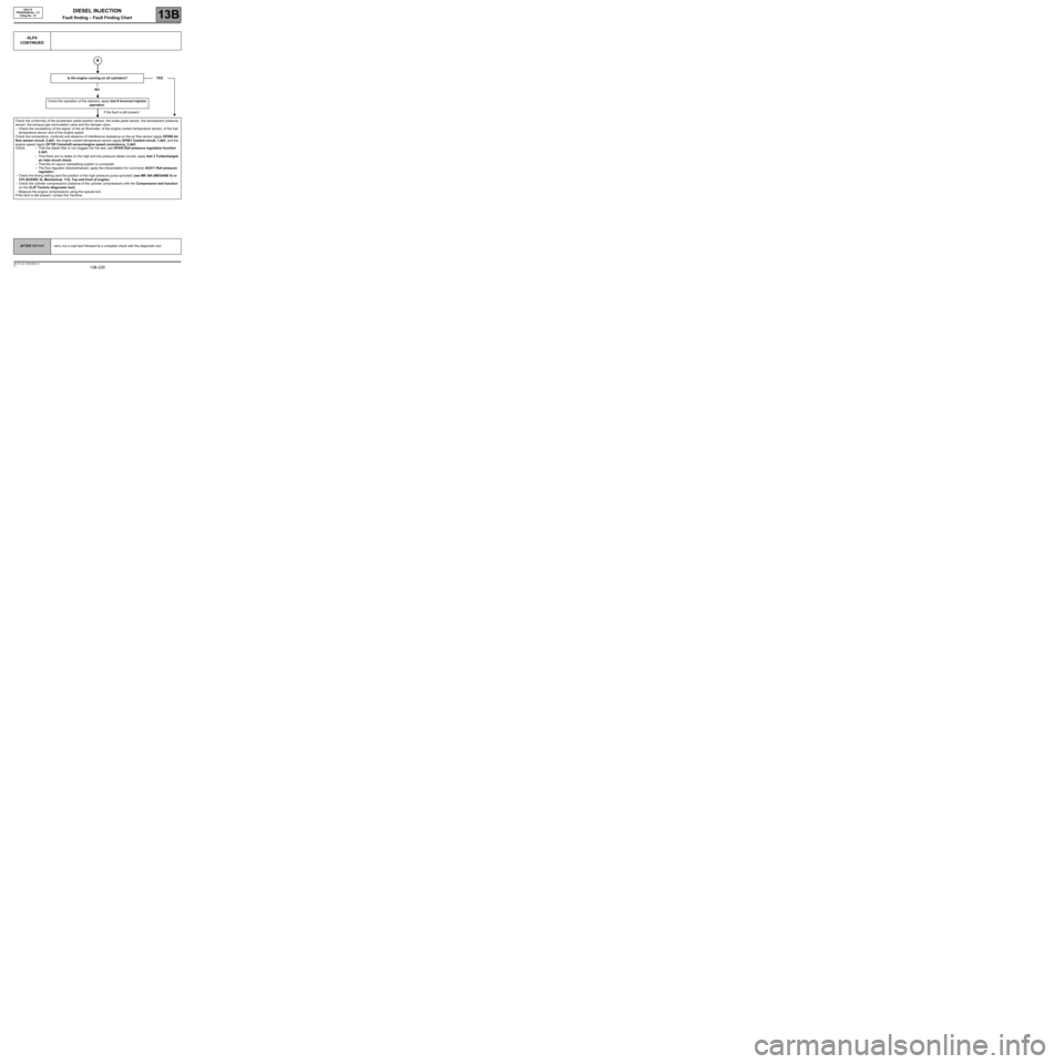
Is the engine running on all cylinders?
NO
Check the operation of the injectors: apply test 8 Incorrect injector
operation.
If the fault is still present
Check the conformity of the accelerator pedal position sensor, the brake pedal sensor, the atmospheric pressure
sensor, the exhaust gas recirculation valve and the damper valve.
–Check the consistency of the signal: of the air flowmeter, of the engine coolant temperature sensor, of the fuel
temperature sensor and of the engine speed.
Check the connections, continuity and absence of interference resistance on the air flow sensor (apply DF056 Air
flow sensor circuit, 2.def), the engine coolant temperature sensor (apply DF001 Coolant circuit, 1.def), and the
engine speed (apply DF195 Camshaft sensor/engine speed consistency, 2.def).
Check: – That the diesel filter is not clogged (for the test, see DF053 Rail pressure regulation function
2.def).
–That there are no leaks on the high and low pressure diesel circuits: apply test 3 Turbocharged
air inlet circuit check.
–That the oil vapour rebreathing system is connected.
–The flow regulator (blocked/seized, apply the interpretation for command: AC011 Rail pressure
regulator).
–Check the timing setting (and the position of the high pressure pump sprocket) (see MR 364 (MEGANE II) or
370 (SCENIC II), Mechanical, 11A, Top and front of engine).
–Check the cylinder compressions (balance of the cylinder compressions with the Compression test function
on the CLIP Technic diagnostic tool).
–Measure the engine compressions using the special tool.
If the fault is still present, contact the Techline.YES
EDC16
PROGRAM No.: C1
Vdiag No.: 51
AFTER REPAIRcarry out a road test followed by a complete check with the diagnostic tool.
Page 230 of 273

DIESEL INJECTION
Fault finding – Fault Finding Chart13B
13B -230V3 MR-372-J84-13B250$855.mif
EDC16
PROGRAM No.: C1
Vdiag No.: 51
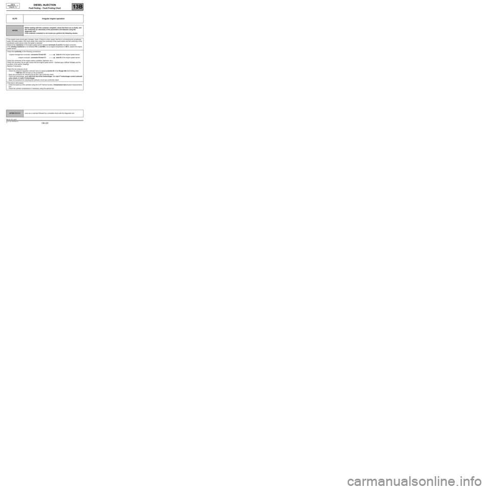
ALP5 Irregular engine operation
NOTESBefore dealing with this customer complaint, check that there are no faults, and
the conformity (or otherwise) of the parameters and statuses using the
diagnostic tool.
If the customer complaint is not ironed out, perform the following checks:
If the engine races during gear changes, check, if there is a floor carpet, that this is not blocking the accelerator
pedal, the brake pedal or the clutch pedal, then check the conformity of the clutch switch and the conformity of the
accelerator pedal sensor when the pedal is released.
Measure the resistance of the engine speed sensor between terminals A and B of its black connector.
If the winding resistance is not between 510 Ω and 850 Ω at an engine temperature of 20˚C, replace the engine
speed sensor.
Check the continuity of the following connections:
–engine management computer, connector B track B1 track A of the engine speed sensor
–engine computer, connector B track C1 track B of the engine speed sensor
Check the conformity of the engine earths (oxidation, tightness, etc.).
Check the mounting, the air gap (check that the engine speed sensor - flywheel gap is 0.5 to 1.8 mm) and the
condition of the sensor (heating).
Replace if necessary.
Check the low pressure circuit.
–Check the pressure regulation solenoid valve by applying section B of the Rough idle fault finding chart.
~ 1600 bar with full load on the accelerator.
–Apply the procedure for checking the air flow; see conformity check.
–Check the turbocharger: apply test 9 Air line at the turbocharger, then test 5 Turbocharger control solenoid
valve check and test 6 Turbocharger.
–Apply the procedure for checking the hydraulic circuit see conformity check.
If the fault is still present:
–Check the balance of the cylinders using the CLIP Technic function, Compression test physical measurements
icon.
–Check the cylinder compressions if necessary using the special tool.
AFTER REPAIRcarry out a road test followed by a complete check with the diagnostic tool.
EDC16_V51_ALP5
Page 234 of 273

DIESEL INJECTION
Fault finding – Fault Finding Chart13B
13B -234V3 MR-372-J84-13B250$855.mif
EDC16
PROGRAM No.: C1
Vdiag No.: 51
ALP7
CONTINUED
Check the connections and wiring of the injectors.
Check the connections and wiring of the engine management computer to the injectors.
Repair if necessary.
Check the high pressure circuit (external leaks) (see the end of ALP6 Fuel circuit external leaks)
Check the timing setting (and the position of the high pressure pump pinion)
Check the lower engine:
–Check the compressions using the Compression Test on the CLIP diagnostic tool or the special tool.
–Only check the engine stand if there is noise or excessive vibration when idling.
If the checks are correct, contact the Techline.
AFTER REPAIRcarry out a road test followed by a complete check with the diagnostic tool.