Page 150 of 273

DIESEL INJECTION
Fault finding – Conformity check13B
13B - 150V3 MR-372-J84-13B250$450.mif
EDC16
PROGRAM NO.: C1
Vdiag No.: 51
STARTING
NOTESOnly check conformity after a complete check using the diagnostic tool. The values
shown in this conformity check are given as a guide.
Test conditions: ENGINE OFF, IGNITION ON.
Order FunctionParameter or Status
checked or ActionDisplay and Notes Fault finding
1Power supplyET001:Computer + after
ignition feedPRESENTIn the event of a fault,
carry out a full fault finding
procedure on the charging
circuit.
2StartingET238:SynchronisationNOT PERFORMEDIn the event of a fault, refer
to fault interpretation
DF195 Camshaft/engine
speed sensor
consistency.
ET076:StartingAUTHORISED:
the injection authorises
startingIf status ET076 is
PROHIBITED, carry out a
complete fault finding
procedure on the
multiplex network.
3Engine
operation.ET038:EngineSTOPPEDNone
4Power supplyPR071:Computer feed
voltage9 V < voltage < 16 VIn the event of a fault,
consult the interpretation
of fault DF047 Computer
supply voltage.
PR358:Sensor reference
voltage3.4 V < voltage < 3.8 VNone
Page 169 of 273

DIESEL INJECTION
Fault finding – Conformity check13B
13B - 169V3 MR-372-J84-13B250$540.mif
EDC16
PROGRAM NO.: C1
Vdiag No.: 51
STARTING
NOTESOnly check conformity after a complete check using the diagnostic tool. The values
shown in this conformity check are given as a guide.
Test Conditions: ENGINE AT IDLE SPEED, COOLANT TEMPERATURE > 80 ˚C.
Order FunctionParameter or Status
checked or ActionDisplay and Notes Fault finding
1Power supplyET001:Computer + after
ignition feedPRESENTIn the event of a fault,
carry out a full fault finding
procedure on the charging
circuit.
2StartingET238:SynchronisationDONEIn the event of a fault, refer
to fault interpretation
DF195 Camshaft/engine
speed sensor
consistency.
ET076:StartingAUTHORISEDIf status ET076 is
PROHIBITED, carry out a
complete fault finding
procedure on the
multiplex network.
3Engine
operation.ET038:EngineRUNNINGNone
4Power supplyPR071:Computer feed
voltage9 V < voltage < 16 VIn the event of a fault,
consult the interpretation
of fault DF047 Computer
supply voltage.
PR358:Sensor reference
voltage3.4 V < voltage < 3.8 VNone
Page 171 of 273

DIESEL INJECTION
Fault finding – Status summary table13B
13B - 171V3 MR-372-J84-13B250$585.mif
EDC16
PROGRAM NO.: C1
Vdiag No.: 51DIESEL INJECTION
Fault finding – Status summary table
Tool status Diagnostic tool title
ET001+ After ignition computer feed
ET003Engine immobiliser
ET004Air conditioning authorisation
ET007Preheating unit control
ET014Monitor cooling fan 1
ET015Monitor cooling fan 2
ET021High speed fan assembly request
ET022Low speed fan assembly request
ET038Engine
ET042Cruise control/speed limiter
ET076Starting
ET077Impact detected
ET079Air conditioning present
ET088Compressor actuation request
ET104Injector code use
ET111Set number of passenger compartment heating resistors (RCH)
ET112Passenger compartment heating resistor cut-off
ET123Brake contact signal no. 2
ET233Clutch pedal
ET238Synchronisation
ET341Immobiliser code programmed
ET405Clutch pedal switch
ET415Deactivation of cruise control/speed limiter
ET589Electric coolant pump control (turbocharger)
ET651EGR programming cut-off
ET703Cruise control/speed limiter buttons
ET704Brake switch no. 1
ET705Brake switch no. 2
MR-372-J84-13B250$585.mif
Page 191 of 273

DIESEL INJECTION
Fault finding – Interpretation of statuses13B
13B - 191V3 MR-372-J84-13B250$630.mif
COMPLETED
EDC16
PROGRAM NO.: C1
Vdiag No.: 51
ET238
SYNCHRONISATION
NOTESSpecial notes:
Only perform these tests if the statuses do not correspond with the system
programming functions.
WARNING
Synchronisation is carried out during the engine starting phase. This is established between the camshaft position
sensor and the TDC sensor.
Once this synchronisation has been carried out, it enables the computer to identify cylinder no. 1 and to calculate
the precise position of the cylinder's Top Dead Centre.
NOT PERFORMED
When the engine is stopped but the ignition switched on, cylinder no. 1 is no longer
indicated.
Status ET238 is NOT DONE; synchronisation between the crankshaft and the camshaft
has not been carried out.
Synchronisation is carried out during the engine starting phase.
Cylinder No. 1 is indicated and synchronisation will be performed once the engine is
started.
Status ET238 is DONE.
If after several attempts to start the engine, status ET238 remains NOT DONE, refer to
the interpretation of the following faults:
–DF005 Engine speed sensor circuit.
–DF097 Camshaft sensor circuit.
If the engine does still not start, consult the Customer complaints section, ALP2
Starting faults.
AFTER REPAIRSwitch off the ignition and carry out a road test followed by a test with the diagnostic tool
EDC16_V51_ET238
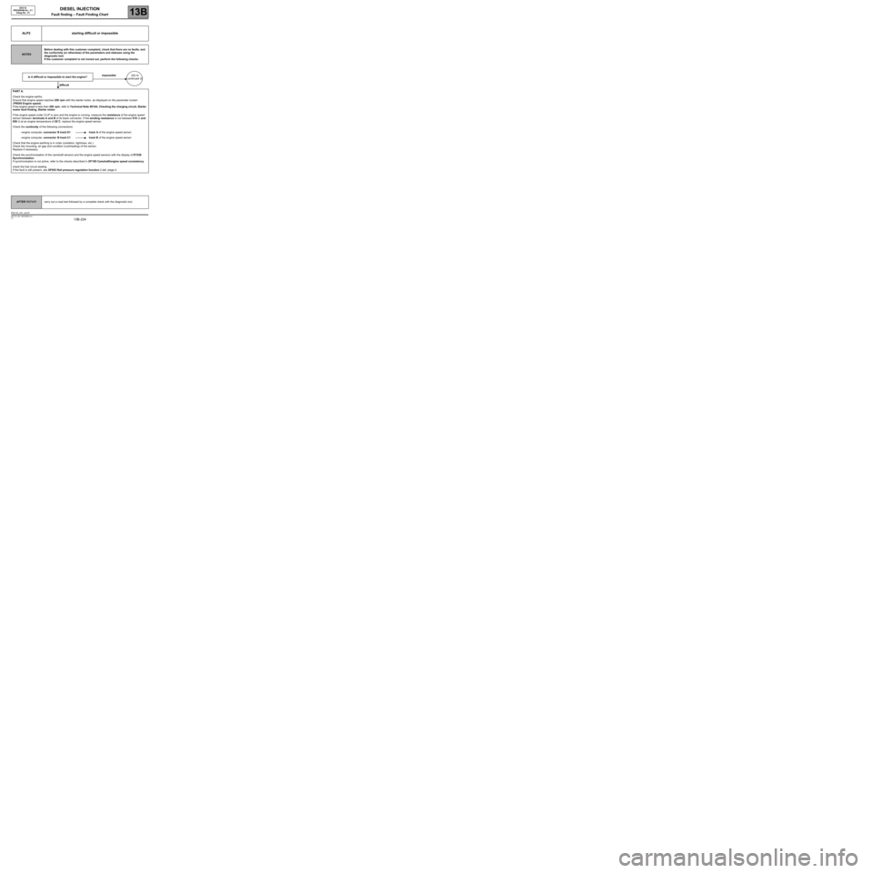
Page 224 of 273

DIESEL INJECTION
Fault finding – Fault Finding Chart13B
13B -224V3 MR-372-J84-13B250$855.mif
EDC16
PROGRAM No.: C1
Vdiag No.: 51
ALP2 starting difficult or impossible
NOTESBefore dealing with this customer complaint, check that there are no faults, and
the conformity (or otherwise) of the parameters and statuses using the
diagnostic tool.
If the customer complaint is not ironed out, perform the following checks:
Is it difficult or impossible to start the engine?impossible(Go to
continued 2)
difficult
PART A:
Check the engine earths.
Ensure that engine speed reaches 250 rpm with the starter motor, as displayed on the parameter screen
(PR055 Engine speed).
If the engine speed is less than 250 rpm, refer to Technical Note 6014A, Checking the charging circuit, Starter
motor fault finding, Starter motor.
If the engine speed under CLIP is zero and the engine is running, measure the resistance of the engine speed
sensor between terminals A and B of its black connector. If the winding resistance is not between 510 Ω and
850 Ω at an engine temperature of 20˚C, replace the engine speed sensor.
Check the continuity of the following connections:
–engine computer, connector B track D1 track A of the engine speed sensor
–engine computer, connector B track C1 track B of the engine speed sensor
Check that the engine earthing is in order (oxidation, tightness, etc.).
Check the mounting, air gap and condition (overheating) of the sensor.
Replace if necessary.
Check the synchronisation of the camshaft sensors and the engine speed sensors with the display of ET238
Synchronisation.
If synchronisation is not active, refer to the checks described in DF195 Camshaft/engine speed consistency.
check the fuel circuit sealing.
If the fault is still present, see DF053 Rail pressure regulation function 2.def, stage 4.
AFTER REPAIRcarry out a road test followed by a complete check with the diagnostic tool.
EDC16_V51_ALP2