2009 RENAULT SCENIC display
[x] Cancel search: displayPage 169 of 273

DIESEL INJECTION
Fault finding – Conformity check13B
13B - 169V3 MR-372-J84-13B250$540.mif
EDC16
PROGRAM NO.: C1
Vdiag No.: 51
STARTING
NOTESOnly check conformity after a complete check using the diagnostic tool. The values
shown in this conformity check are given as a guide.
Test Conditions: ENGINE AT IDLE SPEED, COOLANT TEMPERATURE > 80 ˚C.
Order FunctionParameter or Status
checked or ActionDisplay and Notes Fault finding
1Power supplyET001:Computer + after
ignition feedPRESENTIn the event of a fault,
carry out a full fault finding
procedure on the charging
circuit.
2StartingET238:SynchronisationDONEIn the event of a fault, refer
to fault interpretation
DF195 Camshaft/engine
speed sensor
consistency.
ET076:StartingAUTHORISEDIf status ET076 is
PROHIBITED, carry out a
complete fault finding
procedure on the
multiplex network.
3Engine
operation.ET038:EngineRUNNINGNone
4Power supplyPR071:Computer feed
voltage9 V < voltage < 16 VIn the event of a fault,
consult the interpretation
of fault DF047 Computer
supply voltage.
PR358:Sensor reference
voltage3.4 V < voltage < 3.8 VNone
Page 170 of 273

DIESEL INJECTION
Fault finding – Conformity check13B
13B - 170V3 MR-372-J84-13B250$540.mif
EDC16
PROGRAM NO.: C1
Vdiag No.: 51
PROTECTION
NOTESOnly check conformity after a complete check using the diagnostic tool. The values
shown in this conformity check are given as a guide.
Test Conditions: ENGINE AT IDLE SPEED, COOLANT TEMPERATURE > 80 ˚C.
Order FunctionParameter or Status
checked or ActionDisplay and Notes Fault finding
1Engine
immobiliserET341:Immobiliser code
programmedYESIf status ET341 is locked
on NO (see 87B,
Passenger
compartment
connection unit).
ET003:Engine
immobiliserINACTIVEIf status ET003 is locked
on ACTIVE (see 87B,
Passenger
compartment
connection unit).
2Vehicle impactET077:Impact detectedNOIn the event of a fault, refer
to the interpretation of
fault DF069 Impact
detected signal.
3StartingET076:StartingAUTHORISED:
injection authorises
startingIf status ET076 is
PROHIBITED (see 87B,
Passenger
compartment
connection unit).
Page 181 of 273

DIESEL INJECTION
Fault finding – Interpretation of statuses13B
13B - 181V3 MR-372-J84-13B250$630.mif
EDC16
PROGRAM NO.: C1
Vdiag No.: 51
ET042
CRUISE CONTROL/SPEED LIMITER
NOTESSpecial notes:
Only perform these tests if the statuses do not correspond with the system
programming functions.
NOT DETECTEDIf the vehicle is not fitted with cruise control/speed limiter function buttons, status ET042
is permanently NOT DETECTED. This confirms that the cruise control/speed limiter
function is not present on the vehicle.
If the vehicle is fitted with cruise control or speed limiter function buttons, the main switch
is in rest (or neutral) position and the injection computer has just been programmed or
reprogrammed, then status ET042 is NOT DETECTED.
To activate the cruise control or speed limiter function, press the main switch in the cruise
control position and then in the speed limiter position.
Return to rest position.
The tool displays status ET042: INACTIVE.
If not, several steps must be checked:
1 - Return to the page about testing the multiplex network with the CLIP program.
Repeat the multiplex network test. Re-establish dialogue with the injection computer.
Check status ET042. If ET042 is INACTIVE, the injection computer has detected the
various positions of the main switch. The cruise control/speed limiter is active.
2 - If status ET042 is still NOT DETECTED, check that the owner of the vehicle has not,
sometime in the past, asked for the cruise control/speed limiter function to be
deactivated. Contact the Techline.
AFTER REPAIRSwitch off the ignition and carry out a road test followed by a test with the diagnostic
tool.
EDC16_V51_ET042
Page 202 of 273

DIESEL INJECTION
Fault finding – Interpretation of statuses13B
13B - 202V3 MR-372-J84-13B250$630.mif
EDC16
PROGRAM NO.: C1
Vdiag No.: 51
ET703
CRUISE CONTROL/SPEED LIMITER BUTTONS
NOTESSpecial notes:
Carry out these checks if the statuses do not correspond with system operation
programming.
INACTIVEStatus ET703 becomes INACTIVE when none of the cruise control/speed limiter buttons
is pressed. These buttons are located on the steering wheel.
If status ET703 does not display INACTIVE,
- check the condition of the cruise control/speed limiter “+/-” button and the condition of
its connector.
check the condition of the cruise control/speed limiter "R/0" button and the condition of
its connector.
INCREASEStatus ET703 becomes “PLUS” when the cruise control/speed limiter “+” button is
pressed. This button is on the steering wheel, on the left-hand side.
If status ET703 does not display PLUS, check the condition of the cruise control/speed
limiter “+/-” button, and the condition of its connector. Repair if necessary.
To carry out these checks and measurements in complete safety, observe the
recommendations for removing the driver's front airbag (see MR 364 (Mégane) or 370
(Scénic), Mechanical, 88C, Airbag and seat belt pretensioners, Driver's front
airbag, Removal - Refitting).
Measure the resistance of the following connections while pressing the + button
(on the button tracks):
●Connection code 86G, of component 331.
●Connection code 86M of component 331.
If the resistance is not approximately 300 Ω, check the continuity of the connection when
the button is in the rest position.
If there is continuity, replace the +/- control button.
If there is a repair method (See Technical Note 6015A, Repairing electrical wiring,
Wiring: Precautions for repair), repair the wiring, otherwise replace the wiring.
AFTER REPAIRSwitch off the ignition and carry out a road test followed by a test with the diagnostic tool
EDC16_V51_ET703
Page 210 of 273

DIESEL INJECTION
Fault finding – Interpretation of commands13B
13B -210V3 MR-372-J84-13B250$765.mif
EDC16
PROGRAM No: C1
Vdiag No.: 51
SC002
ENTER INJECTOR CODES
NOTESThis command should be run after the injectors have been replaced and only if the
vehicle has been configured with IMA.
(ET104 USE OF INJECTOR CODES to YES).
If this command is not performed, the DF276 INJECTOR CODE PROGRAMMING
fault will be present.
WARNING
The letters J and Q, and figures 0 and 9 are not used in IMA coding.
If these characters are used the entry will be invalid.
Cylinder no. 1 is the cylinder located at the engine flywheel end.
Procedure to be followed:
–Read the 6-character alphanumeric codes etched on the upper section of the injector bodies.
–Use command SC002.
–Select the cylinder number for the cylinder concerned in the Desired, column, then confirm.
–Enter the injector code displayed for the cylinder.
–Enter the new codes for each cylinder, then confirm.
–When the command is completed, the modified codes appear in the Current column.
–Check that the codes correspond to those read earlier.
–If the codes entered appear in neither the Current column nor the Desired column, check the codes read and
make sure the data has been entered correctly,
The possible confusions are:
digit "1" with the letter "I"
figure 8 with the letter B
figure 5 with the letter S
–Exit fault finding mode.
–Switch off the ignition and wait for 1 min.
–Switch the ignition back on and check for faults.
–DF276 INJECTOR CODE PROGRAMMING should be stored.
If fault DF276 is still present, the command has not been performed correctly.
Start the procedure again and follow the instructions.
If the codes are still not recognised, check whether the computer's standby has been correctly set:
Switch off the ignition and wait for 1 min.
If the warning light flashes when the ignition is switched off, the computer has not been put on standby and the
command will be ignored.
If all these checks still do not enable the command to be confirmed, contact the Techline.
EDC16_V51_SC002
Page 217 of 273

DIESEL INJECTION
Fault finding – Interpretation of commands13B
13B -217V3 MR-372-J84-13B250$765.mif
EDC16
PROGRAM No: C1
Vdiag No.: 51
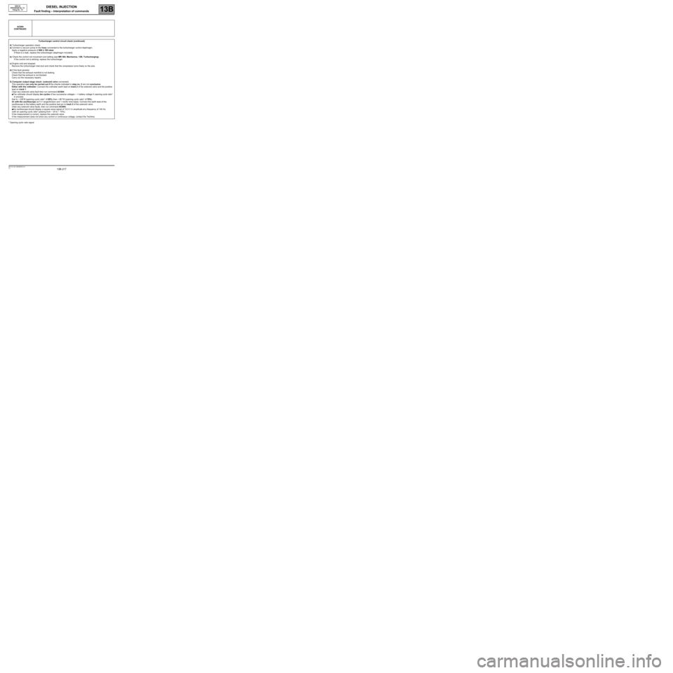
* Opening cyclic ratio signalAC004
CONTINUED
Turbocharger control circuit check (continued)
4) Turbocharger operation check:
a) Connect a vacuum pump to the hose connected to the turbocharger control diaphragm.
Apply a negative pressure of 800 ± 100 mbar:
If there is a leak, replace the turbocharger (diaphragm included).
b) Check the control rod movement and setting (see MR 364, Mechanics, 12B, Turbocharging).
If the control rod is sticking, replace the turbocharger.
c) Engine cold and stopped:
Remove the turbocharger inlet duct and check that the compressor turns freely on the axis.
d) If the fault persists:
Check that the exhaust manifold is not leaking.
Check that the exhaust is not blocked.
Carry out the necessary repairs.
5) Computer output stage check: (solenoid valve connected).
This operation can only be carried out if the checks indicated in step no. 2 are not conclusive.
Either with the voltmeter: Connect the voltmeter earth lead on track 2 of the solenoid valve and the positive
lead on track 1.
Clear any solenoid valve fault then run command AC004:
●The voltmeter should display ten cycles of two successive voltages ~ = battery voltage X opening cycle ratio*
in process.
that is: ~ 2.5 V (opening cyclic ratio* of 20%) then ~ 8.7 V (opening cyclic ratio* of 70%).
Or with the oscilloscope (at 5 V range/division and 1 ms/div time base): Connect the earth lead of the
oscilloscope to the battery earth and the positive test pin to track 2 of the solenoid valve.
Clear any solenoid valve faults, then run command AC004:
●the oscilloscope should display a square wave signal of 12.5 V in amplitude at a frequency of 140 Hz
(with an opening cyclic ratio* passing from ~ 20 to ~ 70%).
If the measurement is correct, replace the solenoid valve.
If the measurement does not show any control or continuous voltage, contact the Techline.
Page 218 of 273

DIESEL INJECTION
Fault finding – Interpretation of commands13B
13B -218V3 MR-372-J84-13B250$765.mif
EDC16
PROGRAM No: C1
Vdiag No.: 51
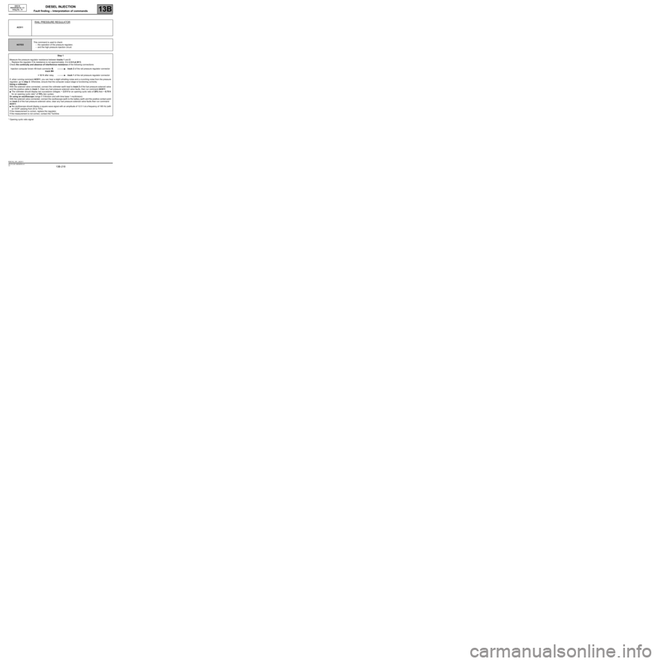
* Opening cyclic ratio signalAC011
RAIL PRESSURE REGULATOR
NOTESThis command is used to check:
–the operation of the pressure regulator,
–and the high pressure injection circuit.
Step 1
Measure the pressure regulator resistance between tracks 1 and 2.
–Replace the regulator if its resistance is not approximately: 3 Ω ± 0.5 at 20˚C.
Check the continuity and absence of interference resistance of the following connections:
Injection computer brown 48-track connector B,
track M4track 2 of the rail pressure regulator connector
+ 12 V after relaytrack 1 of the rail pressure regulator connector
If, when running command AC011, you can hear a slight whistling noise and a crunching noise from the pressure
regulator, go to step 2. Otherwise, ensure that the computer output stage is functioning correctly:
Using a voltmeter:
With the solenoid valve connected, connect the voltmeter earth lead to track 2 of the fuel pressure solenoid valve
and the positive cable to track 1. Clear any fuel pressure solenoid valve faults, then run command AC011:
●The voltmeter should display two successive voltages: ~ 2.5 V for an opening cyclic ratio of 20% then ~ 8.75 V
for an opening cyclic ratio* of 70% (ten cycles).
Or using an oscilloscope (range 5 V/division and with time base 1 ms/division):
With the solenoid valve connected, connect the oscilloscope earth to the battery earth and the positive contact point
on track 2 of the fuel pressure solenoid valve; clear any fuel pressure solenoid valve faults then run command
AC011:
●the oscilloscope should display a square wave signal with an amplitude of 12.5 V at a frequency of 185 Hz (with
an OCR* passing from 20 to 70%).
If the measurement is correct, replace the regulator.
If the measurement is not correct, contact the Techline.
EDC16_V51_AC011
Page 220 of 273

DIESEL INJECTION
Fault finding – Interpretation of commands13B
13B -220V3 MR-372-J84-13B250$765.mif
EDC16
PROGRAM No: C1
Vdiag No.: 51
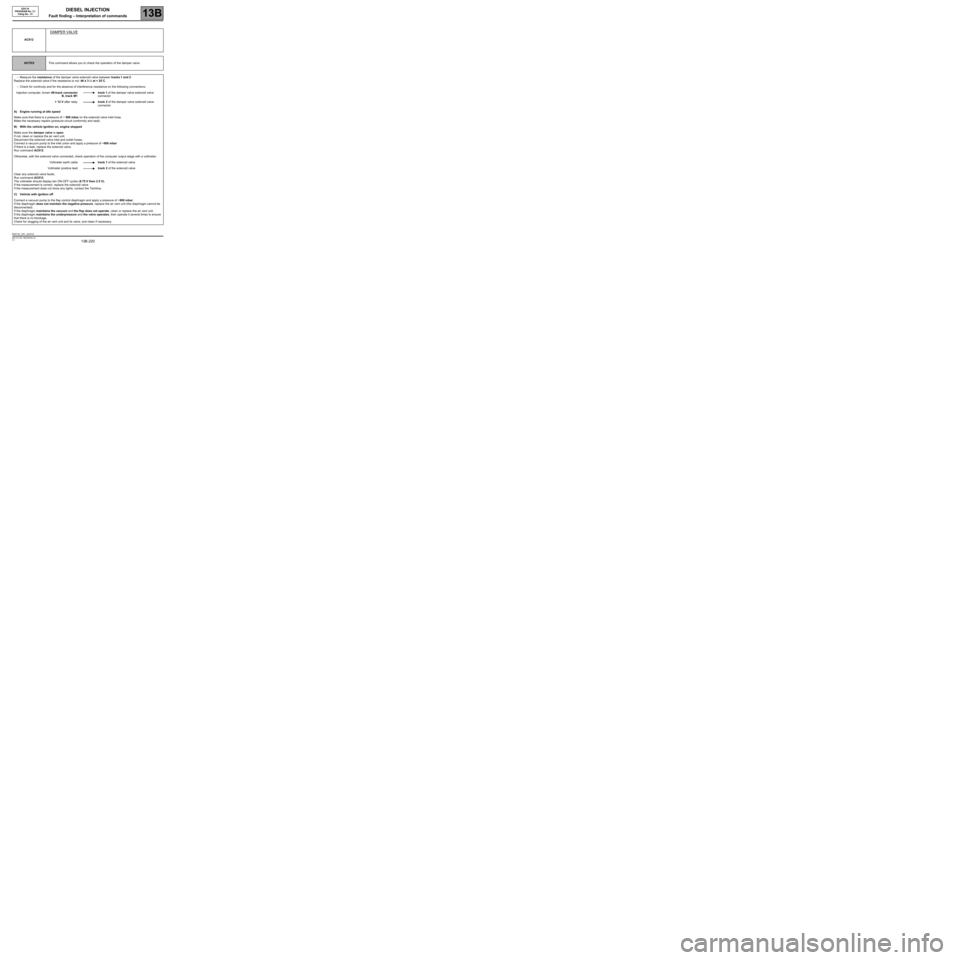
AC012
DAMPER VALVE
NOTESThis command allows you to check the operation of the damper valve.
–Measure the resistance of the damper valve solenoid valve between tracks 1 and 2.
Replace the solenoid valve if the resistance is not: 46 ± 3 Ω at + 25˚C.
–Check for continuity and for the absence of interference resistance on the following connections:
Injection computer, brown 48-track connector
B, track M1track 1 of the damper valve solenoid valve
connector
+ 12 V after relaytrack 2 of the damper valve solenoid valve
connector
A) Engine running at idle speed
Make sure that there is a pressure of ~ 900 mbar on the solenoid valve inlet hose.
Make the necessary repairs (pressure circuit conformity and seal).
B) With the vehicle ignition on, engine stopped
Make sure the damper valve is open.
If not, clean or replace the air vent unit.
Disconnect the solenoid valve inlet and outlet hoses,
Connect a vacuum pump to the inlet union and apply a pressure of ~900 mbar
If there is a leak, replace the solenoid valve.
Run command AC012.
Otherwise, with the solenoid valve connected, check operation of the computer output stage with a voltmeter:
Voltmeter earth cabletrack 1 of the solenoid valve
Voltmeter positive leadtrack 2 of the solenoid valve
Clear any solenoid valve faults,
Run command AC012.
The voltmeter should display ten ON-OFF cycles (8.75 V then 2.5 V).
If the measurement is correct, replace the solenoid valve.
If the measurement does not show any lights, contact the Techline.
C) Vehicle with ignition off
Connect a vacuum pump to the flap control diaphragm and apply a pressure of ~900 mbar:
If the diaphragm does not maintain the negative pressure, replace the air vent unit (the diaphragm cannot be
disconnected).
If the diaphragm maintains the vacuum and the flap does not operate, clean or replace the air vent unit.
If the diaphragm maintains the underpressure and the valve operates, then operate it several times to ensure
that there is no blockage.
Check for clogging of the air vent unit and its valve, and clean if necessary.
EDC16_V51_AC012