2009 RENAULT SCENIC relay
[x] Cancel search: relayPage 175 of 273

DIESEL INJECTION
Fault finding – Interpretation of statuses13B
13B - 175V3 MR-372-J84-13B250$630.mif
NO
EDC16
PROGRAM NO.: C1
Vdiag No.: 51
ET007
PREHEATING UNIT CONTROL
NOTESSpecial notes:
Only perform these tests if the statuses do not correspond with the system
programming functions.
YES
When the vehicle is started from cold, the injection computer controls the pre-
postheating unit so that the vehicle can be started.
Status ET007 becomes YES a few seconds after the ignition is switched on and during
pre/postheating.
If the vehicle does not start and status ET007 becomes YES, check:
–the F2 (70A) supply fuse on the preheating unit, located on the power supply fuse
plate in the engine connection unit, below the Protection and Switching Unit,
–the resistance of the heater plugs.
Replace any plug whose resistance is not below 2 Ω.
If the vehicle starts and status ET007 remains YES during the engine operating phase,
refer to the interpretation of faults:
–DF017 Preheating relay control circuit.
–DF025 Preheating unit diagnostic connection.
After the engine is started and the preheating phase, the injection computer should stop
the pre-postheating unit operating.
Status ET007 should become NO.
In the event that the vehicle does not start and status ET007 remains NO, check the
continuity and absence of interference resistance of the following connections:
Injection computer Track A4 grey
32-track connector CTrack 9 preheating unit
Injection computer Track E2 grey
32-track connector CTrack 8 preheating unit
Repair if necessary.
If the fault is still present, refer to the interpretation of faults:
–DF017 Preheating relay control circuit.
–DF025 Preheating unit diagnostic connection.
AFTER REPAIRCarry out a road test followed by a complete test with the diagnostic tool.
EDC16_V51_ET007
Page 215 of 273

DIESEL INJECTION
Fault finding – Interpretation of commands13B
13B -215V3 MR-372-J84-13B250$765.mif
EDC16
PROGRAM No: C1
Vdiag No.: 51
AC001
PREHEATING UNIT
NOTESThis command is only carried out if the fault DF025 Preheating unit fault finding
connection, or DF017 Preheating unit control circuit is present or stored and if no
other fault is present.
Refer to the Wiring diagrams Technical Note for the vehicle to locate the fuses and
relays concerned.
Connect the diagnostic tool and turn on the ignition.
With the preheating unit connected:
–connect the negative terminal of the voltmeter to track 8 of the preheating unit,
–connect the positive terminal of the voltmeter to the + 12 V battery,
–run command AC001 Preheating unit.
if the voltmeter does not indicate the battery voltage while the command is running (ten 1 second ON/OFF cycles):
1Check the condition of the preheating unit supply fuse F01 (70A).
Replace it if necessary.
2Check the following connections for continuity and the absence of interference resistance:
Injection computer connector C track E2 track 8 of the preheating unit connector
Injection computer connector C track A4 Track 3 of the preheating unit connector
Repair if necessary.
3Check the connections on the pre-postheating unit, heater plugs and injection computer.
Repair if necessary.
4Measure the resistance of the heater plugs. If this resistance is greater than 2 Ω replace the faulty plug(s).
5Check the continuity and absence of interference resistance between:
preheating unit track 1 cylinder 3 heater plug
preheating unit track 2 cylinder 1 heater plug
preheating unit track 6 cylinder 4 heater plug
preheating unit track 7 cylinder 2 heater plug.
6Then check for + 12 V supply on track 4 of the preheating relay connector.
If the fault is still present, replace the preheating unit.
EDC16_V51_AC001
Page 216 of 273

DIESEL INJECTION
Fault finding – Interpretation of commands13B
13B -216V3 MR-372-J84-13B250$765.mif
EDC16
PROGRAM No: C1
Vdiag No.: 51
AC004
TURBOCHARGING SOLENOID VALVE
NOTESThis command is used to check the turbocharging circuit.
This command checks that the turbocharger and the control circuit are working properly.
Introduction
1-Check the sealing of the high pressure air circuit:
Pipes not joined or pierced, pressure sensor disconnected or poorly fitted (seal present), intercooler pierced.
To test the intercooler: stabilise the engine speed between 3,500 and 4,000 rpm with the vehicle stopped and
check that there are no leaks.
Check the resistance of the turbocharging limitation solenoid valve between tracks 1 and 2.
Replace the solenoid valve if its resistance is not 15.4 Ω ± 0.7 at 20˚C.
Check the injection computer connections.
Check for continuity and make sure there is no interference resistance on the following connection:
Injection computer grey 32-track connector C,
track E1Track 1 turbocharging solenoid valve
Repair if necessary.
Check for the presence of + 12 V after relay on track 2 of the turbocharging solenoid valve.
2 - Turbocharger control circuit check
–With the engine stopped, make sure that the control rod is in the resting position.
–Start the engine and make sure that the control rod actuates to the upper stop.
–(when the engine is switched off, the control rod should return to the rest position)
–If the control rod does not move correctly, carry out the following checks:
1) Vacuum pressure command check:
–Disconnect the solenoid valve inlet hose and connect it to a pressure gauge.
–Start the engine and run it at a stable idle speed.
–If the vacuum pressure does not reach 800 mbar ± 100: check the vacuum pressure circuit from the vacuum
pump.
–Stop the engine, reconnect the inlet hoses and go to step no. 2.
2) Solenoid valve control check:
–Disconnect the solenoid valve outlet hose.
–Start the engine and run it at a stable idle speed.
–Place your hand on the solenoid valve and block the outlet union with your thumb.
–If you notice no solenoid valve vibration, check the operation of the computer output (step 5). Solenoid valve
operation check:
–Connect the pressure gauge to the solenoid valve outlet union.
–Start the engine and run it at a stable idle speed.
If the vacuum pressure does not reach 800 mbar ± 100, replace the solenoid valve.
EDC16_V51_AC004
Page 218 of 273

DIESEL INJECTION
Fault finding – Interpretation of commands13B
13B -218V3 MR-372-J84-13B250$765.mif
EDC16
PROGRAM No: C1
Vdiag No.: 51
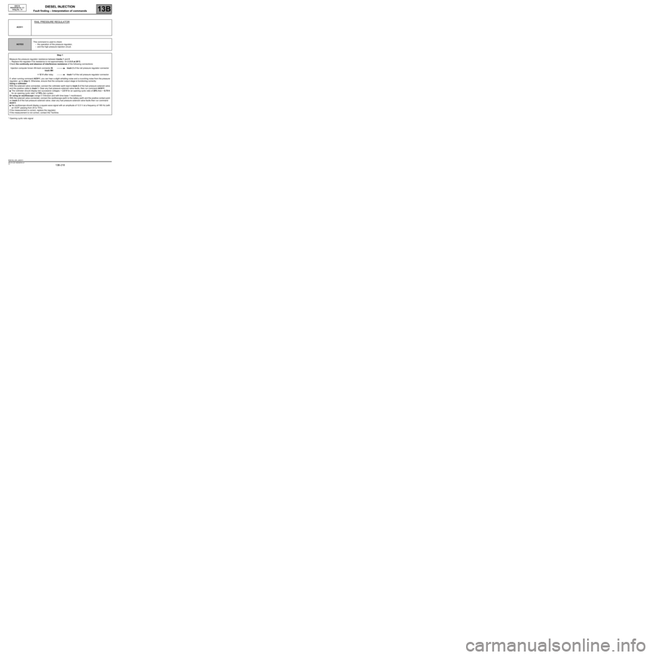
* Opening cyclic ratio signalAC011
RAIL PRESSURE REGULATOR
NOTESThis command is used to check:
–the operation of the pressure regulator,
–and the high pressure injection circuit.
Step 1
Measure the pressure regulator resistance between tracks 1 and 2.
–Replace the regulator if its resistance is not approximately: 3 Ω ± 0.5 at 20˚C.
Check the continuity and absence of interference resistance of the following connections:
Injection computer brown 48-track connector B,
track M4track 2 of the rail pressure regulator connector
+ 12 V after relaytrack 1 of the rail pressure regulator connector
If, when running command AC011, you can hear a slight whistling noise and a crunching noise from the pressure
regulator, go to step 2. Otherwise, ensure that the computer output stage is functioning correctly:
Using a voltmeter:
With the solenoid valve connected, connect the voltmeter earth lead to track 2 of the fuel pressure solenoid valve
and the positive cable to track 1. Clear any fuel pressure solenoid valve faults, then run command AC011:
●The voltmeter should display two successive voltages: ~ 2.5 V for an opening cyclic ratio of 20% then ~ 8.75 V
for an opening cyclic ratio* of 70% (ten cycles).
Or using an oscilloscope (range 5 V/division and with time base 1 ms/division):
With the solenoid valve connected, connect the oscilloscope earth to the battery earth and the positive contact point
on track 2 of the fuel pressure solenoid valve; clear any fuel pressure solenoid valve faults then run command
AC011:
●the oscilloscope should display a square wave signal with an amplitude of 12.5 V at a frequency of 185 Hz (with
an OCR* passing from 20 to 70%).
If the measurement is correct, replace the regulator.
If the measurement is not correct, contact the Techline.
EDC16_V51_AC011
Page 220 of 273

DIESEL INJECTION
Fault finding – Interpretation of commands13B
13B -220V3 MR-372-J84-13B250$765.mif
EDC16
PROGRAM No: C1
Vdiag No.: 51
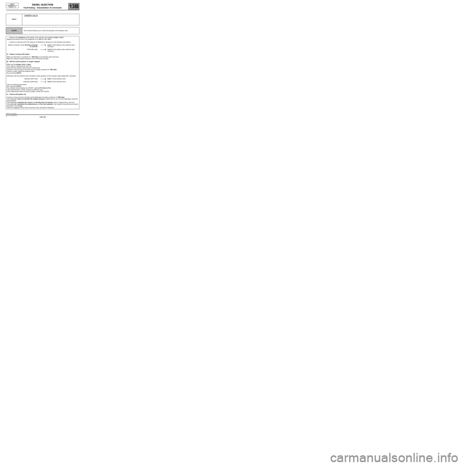
AC012
DAMPER VALVE
NOTESThis command allows you to check the operation of the damper valve.
–Measure the resistance of the damper valve solenoid valve between tracks 1 and 2.
Replace the solenoid valve if the resistance is not: 46 ± 3 Ω at + 25˚C.
–Check for continuity and for the absence of interference resistance on the following connections:
Injection computer, brown 48-track connector
B, track M1track 1 of the damper valve solenoid valve
connector
+ 12 V after relaytrack 2 of the damper valve solenoid valve
connector
A) Engine running at idle speed
Make sure that there is a pressure of ~ 900 mbar on the solenoid valve inlet hose.
Make the necessary repairs (pressure circuit conformity and seal).
B) With the vehicle ignition on, engine stopped
Make sure the damper valve is open.
If not, clean or replace the air vent unit.
Disconnect the solenoid valve inlet and outlet hoses,
Connect a vacuum pump to the inlet union and apply a pressure of ~900 mbar
If there is a leak, replace the solenoid valve.
Run command AC012.
Otherwise, with the solenoid valve connected, check operation of the computer output stage with a voltmeter:
Voltmeter earth cabletrack 1 of the solenoid valve
Voltmeter positive leadtrack 2 of the solenoid valve
Clear any solenoid valve faults,
Run command AC012.
The voltmeter should display ten ON-OFF cycles (8.75 V then 2.5 V).
If the measurement is correct, replace the solenoid valve.
If the measurement does not show any lights, contact the Techline.
C) Vehicle with ignition off
Connect a vacuum pump to the flap control diaphragm and apply a pressure of ~900 mbar:
If the diaphragm does not maintain the negative pressure, replace the air vent unit (the diaphragm cannot be
disconnected).
If the diaphragm maintains the vacuum and the flap does not operate, clean or replace the air vent unit.
If the diaphragm maintains the underpressure and the valve operates, then operate it several times to ensure
that there is no blockage.
Check for clogging of the air vent unit and its valve, and clean if necessary.
EDC16_V51_AC012
Page 221 of 273

DIESEL INJECTION
Fault finding – Interpretation of commands13B
13B -221V3 MR-372-J84-13B250$765.mif
EDC16
PROGRAM No: C1
Vdiag No.: 51
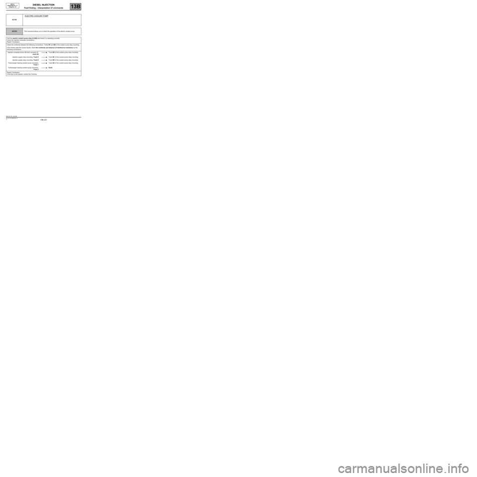
AC195
ELECTRIC COOLANT PUMP
NOTESThis command allows you to check the operation of the electric coolant pump.
Test the electric coolant pump relay (A 20A) and check it is operating correctly.
Check the injection computer connections.
Repair if necessary.
Check the continuity between the following connections: Tracks B1 and B5 of the coolant pump relay mounting.
If the checks yield the correct results, check the continuity and absence of interference resistance on the
following connections:
Injection computer brown 48-track connector B,
track H4Track B2 of the coolant pump relay mounting
Injection supply relay mounting, Track 5Track B1 of the coolant pump relay mounting
Injection supply relay mounting, Track 5Track B5 of the coolant pump relay mounting
Turbocharger bearing coolant pump connector,
Track 1Track B3 of the coolant pump relay mounting
Turbocharger bearing coolant pump connector,
Track 2Earth
Repair if necessary.
If the fault is still present, contact the Techline.
EDC16_V51_AC195