2009 NISSAN TIIDA 205
[x] Cancel search: 205Page 8 of 4331
AT
N
O
P
N
Wiring Diagram - AT -
SSV/B ................................
145
Diagnosis Procedure ........................................... ..146
Component Inspection ........................................ ..147
DTC P1760 OVERRUN CLUTCH SOLENOID
VALVE ............................................................ ..149
Description .......................................................... ..149
CONSULT-III Refe rence Value in Data Monitor
Mode ................................................................... ..
149
On Board Diagnosis Logic .................................. ..149
Possible Cause ................................................... ..149
DTC Confirmation Procedure .............................. ..149
Wiring Diagram - AT - OVRCSV ......................... ..150
Diagnosis Procedure ........................................... ..151
Component Inspection ........................................ ..152
DTC VEHICLE SPEED SENSOR MTR .......... ..154
Description .......................................................... ..154
CONSULT-III Refe rence Value in Data Monitor
Mode ................................................................... ..
154
On Board Diagnosis Logic .................................. ..154
Possible Cause ................................................... ..154
DTC Confirmation Procedure .............................. ..154
Wiring Diagram - AT - VSSMTR ...........................155
Diagnosis Procedure ........................................... ..156
DTC BATT/FLUID TEMP SEN (A/T FLUID
TEMP SENSOR CIRCUIT AND TCM POWER
SOURCE) ....................................................... ..
157
Description .......................................................... ..157
CONSULT-III Refe rence Value in Data Monitor
Mode ................................................................... ..
157
On Board Diagnosis Logic .................................. ..157
Possible Cause ................................................... ..157
DTC Confirmation Procedure .............................. ..157
Wiring Diagram - AT - BA/FTS ............................ ..158
Diagnosis Procedure ........................................... ..159
Component Inspection ........................................ ..161
DTC TURBINE REVOLUTION SENSOR ....... ..163
Description .......................................................... ..163
CONSULT-III Refe rence Value in Data Monitor
Mode ................................................................... ..
163
On Board Diagnosis Logic .................................. ..163
Possible Cause ................................................... ..163
DTC Confirmation Procedure .............................. ..163
Wiring Diagram - AT - PT/SEN ........................... ..164
Diagnosis Procedure ........................................... ..165
CONTROL UNIT (RAM), CONTROL UNIT
(ROM) ............................................................. ..
168
Description .......................................................... ..168
On Board Diagnosis Logic .................................. ..168
Possible Cause ................................................... ..168
DTC Confirmation Procedure .............................. ..168
Diagnosis Procedure ........................................... ..168
MAIN POWER SUPPLY AND GROUND CIR-
CUIT ................................................................ ..169
Wiring Diagram - AT - MAIN ............................... ..169 Diagnosis Procedure ...........................................
..170
PNP, OD SWITCH AND CLOSED THROT-
TLE, WIDE OPEN THROTTLE POSITION
SIGNAL CIRCUI T ............................................ 172
CONSULT-III Reference Va lue in Data Monitor
Mode .................................................................... ..
172
TCM Terminal and Refere nce Value .....................172
Diagnosis Procedure ........................................... ..172
Component Inspection ......................................... ..176
SHIFT POSITION INDICATOR CIRCUIT ........ 177
Description ........................................................... ..177
CONSULT-III Reference Va lue in Data Monitor
Mode .................................................................... ..
177
Diagnosis Procedure ........................................... ..177
TROUBLE DIAGNOSIS FOR SYMPTOMS .... 178
Wiring Diagram - AT - NONDTC ......................... ..178
OD OFF Indicator Lamp Does Not Come On ...... ..181
Engine Cannot Be Started in "P" and "N" Position ..183
In "P" Position, Vehicle Moves Forward or Back-
ward When Pushed ............................................. ..
184
In "N" Position, Vehicle Moves ............................ ..184
Large Shock "N" → "R" Position .......................... ..185
Vehicle Does Not Creep Backward in "R" Position ..186
Vehicle Does Not Creep Forw ard in "D", "2" or "1"
Position ................................................................ ..
187
Vehicle Cannot Be Started from D 1 ..................... ..188
A/T Does Not Shift: D 1→ D 2or Does Not Kick-
down: D 4→ D 2 ..................................................... ..190
A/T Does Not Shift: D 2→ D 3 ................................ ..192
A/T Does Not Shift: D 3→ D 4 ................................ ..193
A/T Does Not Perform Lock-up ........................... ..194
A/T Does Not Hold Lock-up Condition ................. ..195
Lock-up Is Not Released ..................................... ..196
Engine Speed Does Not Return to Idle (Light
Braking D 4→ D 3) ................................................. ..197
A/T Does Not Shift: D 4→ D 3, When OD OFF ...... ..198
A/T Does Not Shift: D 3→ 22, When Selector Lever
"D" → "2" Position ............................................... ..
199
A/T Does Not Shift: 2 2→ 11, When Selector Lever
"2" → "1" Position ................................................ ..
200
Vehicle Does Not Decelerate by Engine Brake ... ..202
TCM Self-Diagnosis Does Not Activate ............... ..205
A/T SHIFT LOCK SYSTEM ............................. 207
Description ........................................................... ..207
Shift Lock System Parts Location ........................ ..207
Wiring Diagram - AT - SHIFT .............................. ..208
Diagnosis Procedure ........................................... ..208
TRANSMISSION CONTROL MODULE .......... 211
Removal and Installation ..................................... ..211
SHIFT CONTROL SYSTEM ............................ 212
Control Device Removal an d Installation ...............212
Control Device Disassembly and Assembly ..........215
Selector Lever Knob Remo val and Installation ......215
Adjustment of A/T Position .................................. ..216
Page 92 of 4331

AT
N
O P
t
1 = 2.5 seconds t 2 = 2.0 seconds t 3 = 1.0 second
How to Erase Self-diagnostic Results 1. If the ignition switch stays ON after repair work, be su re to turn ignition switch OFF once. Wait for at least
5 seconds and then turn it ON again.
2. Perform "Diagnostic Procedure Without CONSULT-III" .
3. Turn ignition switch OFF. (The self-diagnostic results will be erased.) 11th judgement flicker is longer than others.
Line pressure solenoid valve circuit is short-circuited or discon-
nected.
⇒ Go to AT-134 .
12th judgement flicker is longer than others.
CAN communication line is damaged.
⇒ Go to AT-88 .
Lamp turns off.
Park/neutral position (PNP) switch, overdrive control switch,
closed throttle position signal or wide open throttle position signal
circuit is disconnected or TCM is damaged.
(Because overdrive control switch signal, closed throttle position
signal and wide open throttle position signal are input via CAN
communication line malfunction may continue after self-diagno-
sis.)
⇒ Go to AT-205, " TCM Self-Diagnosis
Does Not Activate " .
OD OFF indicator lamp
Page 119 of 4331

Diagnosis Procedure " .
If “STOP VEHICLE” appears on CONSUL T-III screen, go to following step.
- Make sure that “GEAR” shows “2” wh en depressing accelerator pedal to WOT.
- If “TESTING” does not appear on CONSULT-III fo r a long time, select “SELF-DIAG RESULTS” for
“TRANSMISSION”. In case a DTC other than “P0732 A/T 2ND GR FNCTN” is shown, refer to AT-79," CONSULT-III Function (TRANSMISSION) " .
7. Stop vehicle.
8. Follow the instruction displayed. (Check for normal shifting referring to the table below.)
9. Make sure that “OK” is displayed. (If “NG” is displayed, refer to “Diagnostic Procedure”.)
Refer to AT-114, " Diagnosis Procedure " .
Refer to AT-64, " Vehicle Speed at Which Gear Shifting Occurs " .
WITH GST
Follow the procedure “WITH CONSULT-III”.
Diagnosis Procedure INFOID:0000000004305377Control Valve Assembly and Accumulators " .
- Shift solenoid valve B
2. Check resistance between terminal cord assembly harness con- nector terminal and ground. Refer to AT-145, " Wiring Diagram -
AT - SSV/B " .
OK or NG OK >> GO TO 2.
NG >> Repair or replace shift solenoid valve assembly. Control Valve Assembly and Accumulators " .
- Shift solenoid valve B
2. Check solenoid valve by listening for its operating sound while applying battery voltage to the terminal and ground. Refer to AT-145, " Wiring Diagram - AT - SSV/B " .
OK or NG OK >> GO TO 3.
NG >> Repair or replace shift solenoid valve assembly. Control Valve Assembly " .
2. Check to ensure that:
- Valve, sleeve and plug slide along valve bore under their own weight. Vehicle condition Gear on actual transmission shift pattern when screen is changed to 1
→ 2 → 3 → 4
No malfunction exists 1 → 2 → 3 → 4
Malfunction for “A/T 2ND GR FNCTN” exists. 4 → 3 → 3 → 4 Solenoid valve Connector Terminal Resistance (Approx.)
Shift solenoid valve B F30 1 - Ground 5 - 20 Ω SCIA2058E
Page 153 of 4331

AT-148< SERVICE INFORMATION >
DTC P0755 SHIFT SOLENOID VALVE B
• Check resistance between terminal and ground.
Operation Check
• Check solenoid valve by listening for its operating sound while applying battery voltage to the terminal and ground. Solenoid valve Connector Terminal Resistance (Approx.)
Shift solenoid valve B F30 1 - Ground 5 - 20 Ω SCIA2055E
SCIA2058E
Page 518 of 4331
BL
N
O P
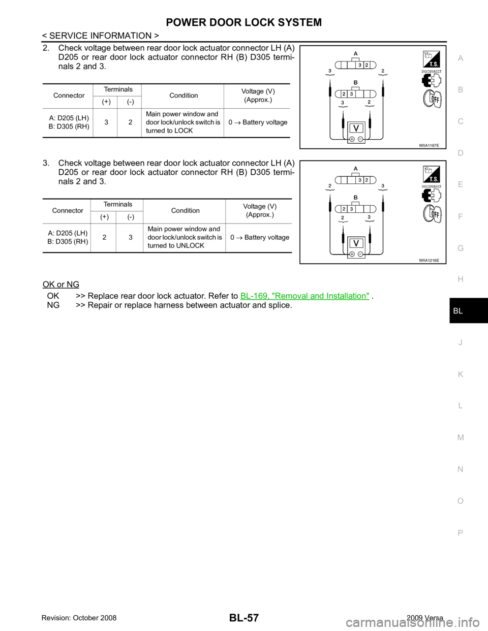
2. Check voltage between rear door lock actuator connector LH (A)
D205 or rear door lock actuator connector RH (B) D305 termi-
nals 2 and 3.
3. Check voltage between rear door lock actuator connector LH (A) D205 or rear door lock actuator connector RH (B) D305 termi-
nals 2 and 3.
OK or NG OK >> Replace rear door lock actuator. Refer to
BL-169, " Removal and Installation " .
NG >> Repair or replace harness between actuator and splice. Connector
Terminals
Condition Voltage (V)
(Approx.)
(+) (-)
A: D205 (LH)
B: D305 (RH) 3 2Main power window and
door lock/unlock switch is
turned to LOCK 0
→ Battery voltage
Page 666 of 4331

TRUNK LID OPENER
BL-205
< SERVICE INFORMATION >
C
D E
F
G H
J
K L
M A
B BL
N
O P
*1: With continuously variable transmission (CVT) or automatic transmission (A/T).
*2: With manual transmission (M/T).
CONSULT-III Function (BCM) INFOID:0000000004305106
CONSULT-III can display each diagnostic item using the diagnostic test modes shown following. 29 V
Back door request
switch (hatchback) —Press back door request switch. 0
Other than above 5
Trunk opener request
switch (sedan) —Press trunk opener request switch. 0
Other than above 5
31 BR Steering lock solenoid
ground — — 0
32 GR Steering lock solenoid
communication signal LOCKWhen Intelligent Key is inside vehicle,
press ignition knob switch.
Other than above 5
33 R Rear floor antenna (+)
signal
LOCK• Any door open
→ all door close
• Press ignition knob switch: ON (Ignition
knob switch)
34 G Rear floor antenna (-)
signal
37 BR Front outside antenna
RH (+) signal
LOCK Press door request switch RH.
38 Y Front outside antenna
RH (-) signal
Terminal
Wire
Color Item Condition
Voltage (V)Approx.
Ignition
Switch
Position Operation or Conditions SIIA1911J
PIIB5502J
SIIA1910J
BCM
diagnostic test item Diagnostic mode Description
Inspection by part WORK SUPPORT
Supports inspections and adjustments. Commands are transmitted to the
BCM for setting the status suitable for required operation, input/output sig-
nals are received from the BCM and received date is displayed.
DATA MONITOR Displays BCM input/output data in real time.
ACTIVE TEST Operation of electrical loads can be checked by sending drive signal to
them.
SELF-DIAG RESULTS Displays BC M self-diagnosis results.
CAN DIAG SUPPORT MNTR The result of transmit/receive diagnosis of CAN communication can be
read.
ECU PART NUMBER BCM part number can be read.
CONFIGURATION Performs BCM configuration read/write functions.
Page 949 of 4331
CVT
N
O
P
N
Precaution Necessary fo
r Steering Wheel Rota-
tion After Battery Disconnect ............................... ..
189
Precaution for On Board Diagnosis (OBD) System
of CVT and Engine .............................................. ..
190
Service After Replacing TCM and Transaxle As-
sembly ................................................................. ..
190
Removal and Installation Procedure for CVT Unit
Connector ............................................................ ..
191
Precaution ........................................................... ..192
Service Notice or Precaution ............................... ..193
PREPARATION .............................................. ..195
Special Service Tool ........................................... ..195
Commercial Service Tool .................................... ..195
CVT FLUID ..................................................... ..196
Checking CVT Fluid ............................................ ..196
Changing CVT Fluid ............................................ ..197
CVT Fluid Cooler Cleanin g ...................................197
CVT SYSTEM ... .............................................. ..201
Cross-Sectional View - RE0F08B ....................... ..201
Control System .................................................... ..202
Hydraulic Control System ......................................203
TCM Function ...................................................... ..203
CAN Communication ........................................... ..204
Input/Output Signal of TCM ................................. ..204
Line Pressure and Secondary Pressure Control . ..205
Shift Control ........................................................ ..205
Lock-up and Select Control ................................. ..207
Control Valve ....................................................... ..207
ON BOARD DIAGNOSTIC (OBD) SYSTEM .. ..209
Introduction ......................................................... ..209
OBD-II Function for CVT System ........................ ..209
One or Two Trip Detection Logic of OBD-II ........ ..209
OBD-II Diagnostic Trouble Code (DTC) .............. ..209
Malfunction Indicator Lamp (MIL) ........................ ..210
TROUBLE DIAGNOSIS ................................. ..212
DTC Inspection Priority Chart ............................. ..212
Fail-Safe .............................................................. ..212
How to Perform Trouble Diagnosis for Quick and
Accurate Repair ........... .........................................
213
CVT Electrical Parts Location ............................. ..218
Circuit Diagram ................................................... ..219
Inspections before Trouble Diagnosis ................. ..219
Road Test ............................................................ ..223
Check before Engine Is Started ............................224
Check at Idle ....................................................... ..224
Cruise Test .......................................................... ..226
Vehicle Speed When Shifting Gears ................... ..228
TCM Terminal and Reference Value ................... ..228
CONSULT-III Function (TRANSMISSION) ......... ..230
Diagnosis Procedu re without CONSULT-III ........ ..237
DTC U1000 CAN COMMUNICATION LINE ... ..238
Description .......................................................... ..238
On Board Diagnosis Logic .................................. ..238
Possible Cause ................................................... ..238 DTC Confirmation Procedure ..............................
..238
Wiring Diagram - CVT - CAN ............................... ..239
Diagnosis Procedure ........................................... ..240
DTC U1010 TRANSMISSION CONTROL
MODULE (CAN) .............................................. 241
Description ........................................................... ..241
On Board Diagnosis Logic ................................... ..241
Possible Cause .................................................... ..241
DTC Confirmation Procedure .............................. ..241
Diagnosis Procedure ........................................... ..241
DTC P0703 STOP LAMP SWITCH CIRCUIT . 242
Description ........................................................... ..242
CONSULT-III Reference Va lue in Data Monitor
Mode .................................................................... ..
242
On Board Diagnosis Logic ................................... ..242
Possible Cause .................................................... ..242
DTC Confirmation Procedure .............................. ..242
Diagnosis Procedure ........................................... ..242
DTC P0705 PARK/NEUTRAL POSITION
SWITCH ........................................................... 244
Description ........................................................... ..244
CONSULT-III Reference Va lue in Data Monitor
Mode .................................................................... ..
244
On Board Diagnosis Logic ................................... ..244
Possible Cause .................................................... ..244
DTC Confirmation Procedure .............................. ..244
Wiring Diagram - CVT - PNP/SW ........................ ..245
Diagnosis Procedure ........................................... ..246
Component Inspection ......................................... ..247
DTC P0710 CVT FLUID TEMPERATURE
SENSOR CIRCUIT .......................................... 249
Description ........................................................... ..249
CONSULT-III Reference Va lue in Data Monitor
Mode .................................................................... ..
249
On Board Diagnosis Logic ................................... ..249
Possible Cause .................................................... ..249
DTC Confirmation Procedure .............................. ..249
Wiring Diagram - CVT - FTS ............................... ..250
Diagnosis Procedure ........................................... ..251
Component Inspection ......................................... ..252
DTC P0715 INPUT SPEED SENSOR CIR-
CUIT (PRI SPEED SENSOR) .......................... 254
Description ........................................................... ..254
CONSULT-III Reference Va lue in Data Monitor
Mode .................................................................... ..
254
On Board Diagnosis Logic ................................... ..254
Possible Cause .................................................... ..254
DTC Confirmation Procedure .............................. ..254
Wiring Diagram - CVT - PRSCVT ........................ ..255
Diagnosis Procedure ........................................... ..256
DTC P0720 VEHICLE SPEED SENSOR CVT
(SECONDARY SPEED SENSOR) .................. 258
Description ........................................................... ..258
Page 1149 of 4331

CVT SYSTEM
CVT-205
< SERVICE INFORMATION >
[RE0F08B] D
E
F
G H
I
J
K L
M A
B CVT
N
O P
*1: Input by CAN communications.
*2: Output by CAN communications.
*3: If these input and output signals are different, the TCM triggers the fail-safe function.
Line Pressure and Secondary Pressure Control INFOID:0000000004305579
• When an input torque signal equivalent to the engine drive force is sent from the ECM to the TCM, the TCM
controls the line pressure solenoid valve and secondary pressure solenoid valve.
• This line pressure solenoid controls the pressure regulat or valve as the signal pressure and adjusts the pres-
sure of the operating oil discharged from the oil pump to the line pressure most appropriate to the driving
state. Secondary pressure is cont rolled by decreasing line pressure.
NORMAL CONTROL Optimize the line pressure and secondary pressure, dependi ng on driving conditions, on the basis of the throt-
tle position, the engine speed, the primary pulley (input ) revolution speed, the secondary pulley (output) revo-
lution speed, the brake signal, the PNP switch signal, the lock-up signal, the voltage, the target gear ratio, the
fluid temperature, and the fluid pressure.
FEEDBACK CONTROL When controlling the normal fluid pressure or the sele cted fluid pressure, the secondary pressure can be set
more accurately by using the fluid pressure sensor to detect the secondary pressure and controlling the feed-
back.
Shift Control INFOID:0000000004305580
In order to select the gear ratio which can obtain the dr iving force in accordance with driver's intention and the
vehicle condition, TCM monitors the driving conditions, such as the vehicle speed and the throttle position and
selects the optimum gear ratio, and determines the gear change steps to the gear ratio. Then send the com-
Out-
put Step motor X X
TCC solenoid valve X X X
Lock-up select solenoid valve X X X
Line pressure solenoid valve X X X X
Secondary pressure solenoid valve X X X
O/D OFF indicator signal (*2)
X X
Control item
Fluid
pressure
control Select con-
trol Shift control
Lock-up
control CAN com-
munication
control Fail-safe
function
(*3) SCIA1846E