2009 NISSAN TIIDA key
[x] Cancel search: keyPage 575 of 4331
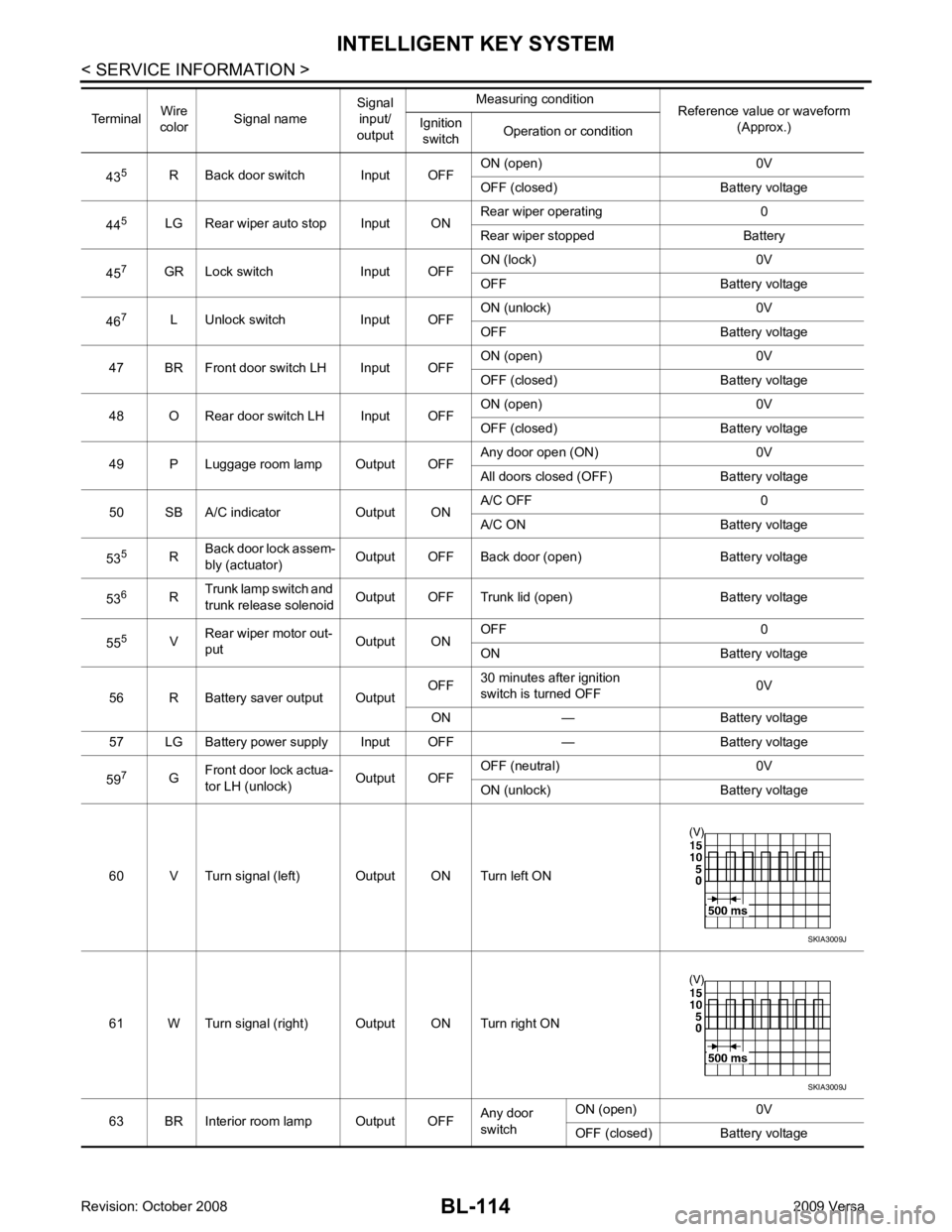
BL-114< SERVICE INFORMATION >
INTELLIGENT KEY SYSTEM
43 5
R Back door switch Input OFF ON (open) 0V
OFF (closed) Ba ttery voltage
44 5
LG Rear wiper auto stop Input ON Rear wiper operating 0
Rear wiper stopped Battery
45 7
GR Lock switch Input OFF ON (lock) 0V
OFF Battery voltage
46 7
L Unlock switch Input OFF ON (unlock) 0V
OFF Battery voltage
47 BR Front door switch LH Input OFF ON (open) 0V
OFF (closed) Ba ttery voltage
48 O Rear door switch LH Input OFF ON (open) 0V
OFF (closed) Ba ttery voltage
49 P Luggage room lamp Output OFF Any door open (ON) 0V
All doors closed (OFF) Battery voltage
50 SB A/C indicator Output ON A/C OFF 0
A/C ON Battery voltage
53 5
RBack door lock assem-
bly (actuator) Output OFF Back door (open) Battery voltage
53 6
RTrunk lamp switch and
trunk release solenoid Output OFF Trunk lid (open) Battery voltage
55 5
VRear wiper motor out-
put Output ONOFF 0
ON Battery voltage
56 R Battery saver output Output OFF
30 minutes after ignition
switch is turned OFF 0V
ON — Battery voltage
57 LG Battery power supply Input OFF — Battery voltage
59 7
GFront door lock actua-
tor LH (unlock) Output OFFOFF (neutral) 0V
ON (unlock) Battery voltage
60 V Turn signal (left) Output ON Turn left ON
61 W Turn signal (right) Output ON Turn right ON
63 BR Interior room lamp Output OFF Any door
switch ON (open) 0V
OFF (closed) Battery voltage
Terminal
Wire
color Signal name Signal
input/
output Measuring condition
Reference value or waveform
(Approx.)
Ignition
switch Operation or condition SKIA3009J
SKIA3009J
Page 576 of 4331
BL
N
O P
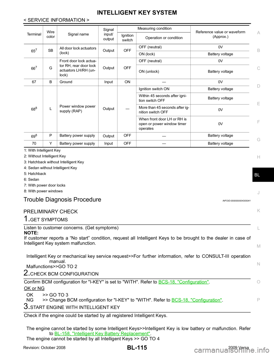
1: With Intelligent Key
2: Without Intelligent Key
3: Hatchback without Intelligent Key
4: Sedan without Intelligent Key
5: Hatchback
6: Sedan
7: With power door locks
8: With power windows
Trouble Diagnosis Procedure INFOID:0000000004305041
PRELIMINARY CHECK Configuration " .
OK or NG OK >> GO TO 3
NG >> Change BCM configuration for "I-KEY" to "WITH". Refer to BCS-18, " Configuration " .
Intelligent Key Battery Replacement " .
The engine cannot be started by all Intelligent Keys >> GO TO 4 65
7
SBAll door lock actuators
(lock) Output OFFOFF (neutral) 0V
ON (lock) Battery voltage
66 7
GFront door lock actua-
tor RH, rear door lock
actuators LH/RH (un-
lock) Output OFFOFF (neutral) 0V
ON (unlock) Battery voltage
67 B Ground Input ON — 0V
68 8
LPower window power
supply (RAP) Output —Ignition switch ON Battery voltage
Within 45 seconds after igni-
tion switch OFF Battery voltage
More than 45 seconds after ig-
nition switch OFF 0V
When front door LH or RH is
open or power window timer
operates 0V
69 8
P Battery power supply
OutputOFF
— Battery voltage
70 Y Battery power supply Input OFF — Battery voltage
Terminal
Wire
color Signal name Signal
input/
output Measuring condition
Reference value or waveform
(Approx.)
Ignition
switch Operation or condition
Page 577 of 4331
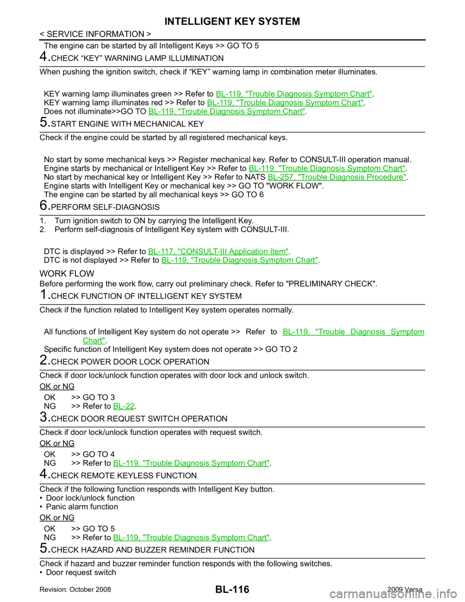
Trouble Diagnosis Symptom Chart " .
KEY warning lamp illuminates red >> Refer to BL-119, " Trouble Diagnosis Symptom Chart " .
Does not illuminate>>GO TO BL-119, " Trouble Diagnosis Symptom Chart " .
Trouble Diagnosis Symptom Chart " .
No start by mechanical key or Intelligent Key >> Refer to NATS BL-257, " Trouble Diagnosis Procedure " .
Engine starts with Intelligent Key or mechanical key >> GO TO "WORK FLOW".
The engine can be started by all mechanical keys >> GO TO 6 CONSULT-III Application Item " .
DTC is not displayed >> Refer to BL-119, " Trouble Diagnosis Symptom Chart " .
WORK FLOW
Before performing the work flow, carry out prel iminary check. Refer to "PRELIMINARY CHECK". Trouble Diagnosis Symptom
Chart " .
Specific function of Intelligent Ke y system does not operate >> GO TO 2OK >> GO TO 3
NG >> Refer to BL-22 .
OK >> GO TO 4
NG >> Refer to BL-119, " Trouble Diagnosis Symptom Chart " .
OK >> GO TO 5
NG >> Refer to BL-119, " Trouble Diagnosis Symptom Chart " .
Page 578 of 4331
BL
N
O P
• Intelligent Key button
OK or NG OK >> GO TO 6
NG >> Refer to BL-119, " Trouble Diagnosis Symptom Chart " .
System
Description " .
OK or NG OK >> GO TO 7
NG >> Refer to BL-119, " Trouble Diagnosis Symptom Chart " .
System
Description " .
OK or NG OK >> Inspection End.
NG >> Refer to BL-119, " Trouble Diagnosis Symptom Chart " .
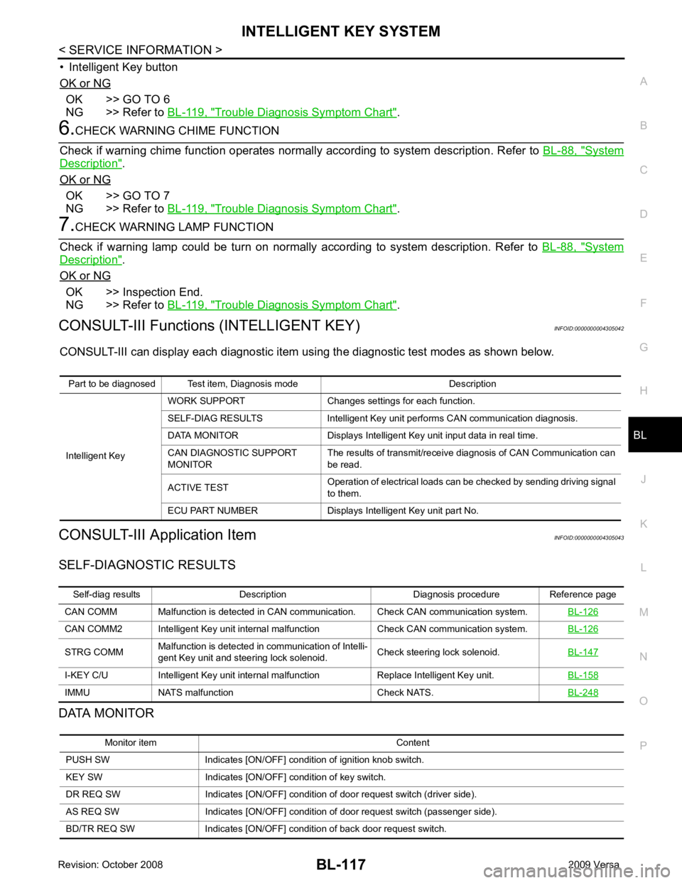
CONSULT-III Functions (INTELLIGENT KEY) INFOID:0000000004305042
CONSULT-III can display each diagnostic item using the diagnostic test modes as shown below.
CONSULT-III Application Item INFOID:0000000004305043
SELF-DIAGNOSTIC RESULTS
DATA MONITOR Part to be diagnosed Test item, Diagnosis mode Description
Intelligent Key WORK SUPPORT Changes settings for each function.
SELF-DIAG RESULTS Intelligent Key unit performs CAN communication diagnosis.
DATA MONITOR Displays Intelligent Key unit input data in real time.
CAN DIAGNOSTIC SUPPORT
MONITOR The results of transmit/receive diagnosis of CAN Communication can
be read.
ACTIVE TEST Operation of electrical loads can be checked by sending driving signal
to them.
ECU PART NUMBER Displays Intelligent Key unit part No. Self-diag results Description Diagnosis procedure Reference page
CAN COMM Malfunction is detected in CAN co mmunication. Check CAN communication system. BL-126CAN COMM2 Intelligent Key unit internal malfunction Check CAN communication system.
BL-126STRG COMM
Malfunction is detected in communication of Intelli-
gent Key unit and steering lock solenoid. Check steering lock solenoid.
BL-147I-KEY C/U Intelligent Key unit internal ma
lfunction Replace Intelligent Key unit. BL-158IMMU NATS malfunction Check NATS.
BL-248Monitor item Content
PUSH SW Indicates [ON/OFF] condition of ignition knob switch.
KEY SW Indicates [ON/OFF] condition of key switch.
DR REQ SW Indicates [ON/OFF] condition of door request switch (driver side).
AS REQ SW Indicates [ON/OFF] condition of door request switch (passenger side).
BD/TR REQ SW Indicates [ON/OFF] condition of back door request switch.
Page 579 of 4331

Test item Description
DOOR LOCK/UNLOCK This test is able to check door lock/unlock operation.
• The all door lock actuators are unlocked when “ALL UNLK” on CONSULT-III screen is touched.
• The all door lock actuators are locked when “LOCK” on CONSULT-III screen is touched.
ANTENNA This test is able to check Intelligent Key antenna operation.
When the following conditions are met, hazard warning lamps flash.
• Inside key antenna (front console) detects Intelligent Key, when “ROOM ANT1” on CONSULT- III screen is touched.
• Inside key antenna (instrument panel and rear floor) detects Intelligent Key, when “ROOM
ANT2” on CONSULT-III screen is touched.
• Outside key antenna (driver side) detects Intelligent Key, when “DRIVER ANT” on CONSULT-III screen is touched.
• Outside key antenna (passenger side) detects Intelligent Key, when “ASSIST ANT” on CON- SULT-III screen is touched.
• Outside key antenna (rear bumper) detects Intelligent Key, when “BK DOOR ANT” on CON-
SULT-III screen is touched.
OUTSIDE BUZZER(S)
(DRIVER DOOR), (TRUNK) *This test is able to check Intelligent Key warning buzzer operation.
Intelligent Key warning buzzer sounds when “ON” on CONSULT-III screen is touched.
INSIDE BUZZER
(CHIME) This test is able to check Intelligent Key warning chime (Instrument panel) operation.
• Take away warning chime sounds when “TAKE OUT” on CONSULT-III screen is touched.
• Ignition switch warning chime sounds when “KNOB” on CONSULT-III screen is touched.
• Ignition key warning chime sounds when “KEY” on CONSULT-III screen is touched.
INDICATOR This test is able to check warning lamp operation.
• “KEY” Warning lamp (Green) illuminates when “BLUE ON” on CONSULT-III screen is touched.
• “KEY” Warning lamp (Red) illuminates when “RED ON” on CONSULT-III screen is touched.
• “LOCK” Warning lamp illuminates when “KNOB ON” on CONSULT-III screen is touched.
• “KEY” Warning lamp (Green) flashes when “BLUE IND” on CONSULT-III screen is touched.
• “KEY” Warning lamp (RED) flashes when “BLUE IND” on CONSULT-III screen is touched.
• “P-SHIFT” Warning lamp flashes when “K NOB ON” on CONSULT-III screen is touched.
Page 580 of 4331

BL
N
O P
Trouble Diagnosis Symptom Chart INFOID:0000000004305044
KEY WARNING LAMP (GREEN) ILLUMINATES NOTE: Monitor item Description
CONFIRM KEY FOB ID It can be checked whether Intelligent Key ID code is registered or not in this mode.
TAKE OUT FROM WINDOW
WARN Take away warning chime (from window) mode can be changed to operate (ON) or not operate
(OFF) with this mode. The operation mode will be changed when “CHANGE SETT” on CONSULT-
III screen is touched.
LOW BAT OF KEY FOB WARN Intelligent Key low battery warning mode can be changed to operate (ON) or not operate (OFF)
with this mode. The operation mode will be changed when “CHANGE SETT” on CONSULT-III
screen is touched.
ANSWER BACK FUNCTION Buzzer reminder function mode by Intelligent button can be changed to operate (ON) or not oper-
ate (OFF) with this mode. The operation mode will be changed when “CHANGE SETT” on CON-
SULT-III screen is touched.
SELECTIVE UNLOCK FUNC-
TION Selective unlock function mode can be changed to operate (ON) or not operate (OFF) with this
mode. The operation mode will be changed when “CHANGE SETT” on CONSULT-III screen is
touched.
ANTI KEY LOCK IN FUNCTION Key reminder function mode can be changed to operate (ON) or not operate (OFF) with this mode.
The operation mode will be changed when “CHANGE SETT” on CONSULT-III screen is touched.
HORN WITH KEYLESS LOCK Horn reminder function mode by Intelligent Key remote control button can be changed to operate
(ON) or not operate (OFF) with this mode. The operation mode will be changed when “CHANGE
SETT” on CONSULT-III screen is touched.
HAZARD ANSWER BACK Hazard reminder function mode can be selected from the following with this mode. The operation
mode will be changed when “CHANGE SE TT” on CONSULT-III screen is touched.
• LOCK ONLY: Door lock operation only
• UNLOCK ONLY: Door unlock operation only
• LOCK/UNLOCK: Lock/Unlock operation
• OFF: Non-operation
ANSWER BACK WITH I-KEY
LOCK Buzzer reminder function (lock operation) mode by door request switch (driver side, passenger
side and back door side) can be selected from the following with this mode. The operation mode
will be changed when “ CHANGE SETT” on CONSULT- III screen is touched.
• BUZZER: Sound buzzer
• OFF: Non-operation
ANSWER BACK WITH I-KEY UN-
LOCK Buzzer reminder function (unlock operation) mode by door request switch can be changed to op-
erate (ON) or not operate (OFF) with this mode.
AUTO RELOCK TIMER Auto door lock timer mode can select the following with this mode.
• 1 minute
• OFF: Non-operation
PANIC ALARM DELAY Panic alarm button's pressing time on Intelligent Key remote control button can be selected from
the following with this mode. The operation mode will be changed when “CHANGE SETT” on
CONSULT-III screen is touched.
• 0.5 second
• 1.5 second
• OFF: Non-operation
P/W DOWN DELAY Unlock button's pressing time on Intelligent Key remote control button can be selected from the
following with this mode. The operation mode will be changed when “CHANGE SETT” on CON-
SULT-III screen is touched.
• 3 seconds
• 5 seconds
• OFF: Non-operation
ENGINE START BY I-KEY Engine start function mode can be changed to operate (ON) or not operate (OFF) with this mode.
The operation mode will be changed when “CHANGE SETT” on CONSULT-III screen is touched.
LOCK/UNLOCK BY I-KEY Door lock/unlock function by door request switch (driver side, passenger side and back door side)
mode can be changed to operate (ON) or not operate (OFF) with this mode. The operation mode
will be changed when “ CHANGE SETT” on CONSULT- III screen is touched.
Page 581 of 4331
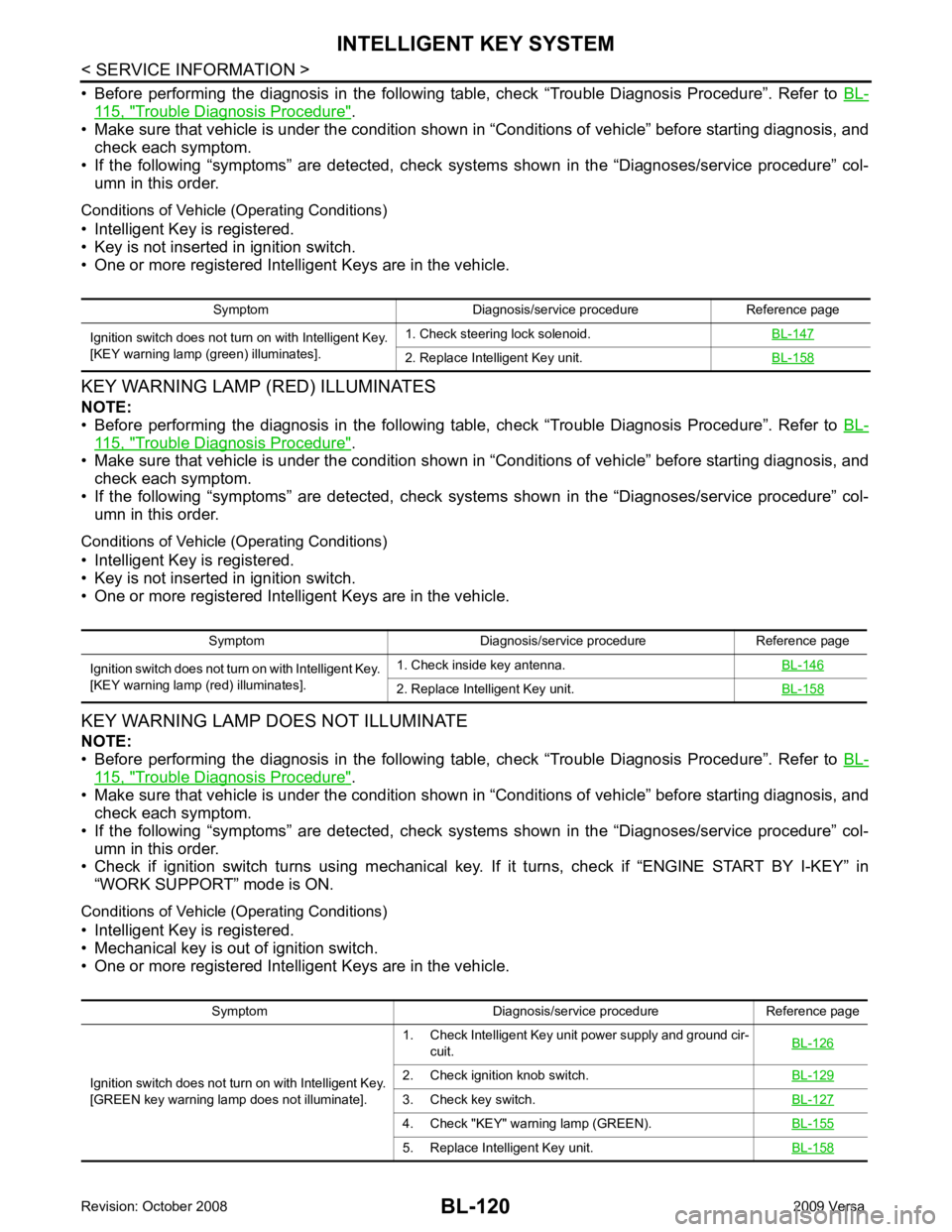
115, " Trouble Diagnosis Procedure " .
• Make sure that vehicle is under the condition shown in “Conditions of vehicle” before starting diagnosis, and
check each symptom.
• If the following “symptoms” are detected, check systems shown in the “Diagnoses/service procedure” col- umn in this order.
Conditions of Vehicle (Operating Conditions)
• Intelligent Key is registered.
• Key is not inserted in ignition switch.
• One or more registered Intelligent Keys are in the vehicle.
KEY WARNING LAMP (RED) ILLUMINATES
NOTE:
• Before performing the diagnosis in the following table, check “Trouble Diagnosis Procedure”. Refer to BL-115, " Trouble Diagnosis Procedure " .
• Make sure that vehicle is under the condition shown in “Conditions of vehicle” before starting diagnosis, and
check each symptom.
• If the following “symptoms” are detected, check systems shown in the “Diagnoses/service procedure” col- umn in this order.
Conditions of Vehicle (Operating Conditions)
• Intelligent Key is registered.
• Key is not inserted in ignition switch.
• One or more registered Intelligent Keys are in the vehicle.
KEY WARNING LAMP DOES NOT ILLUMINATE
NOTE:
• Before performing the diagnosis in the following table, check “Trouble Diagnosis Procedure”. Refer to BL-115, " Trouble Diagnosis Procedure " .
• Make sure that vehicle is under the condition shown in “Conditions of vehicle” before starting diagnosis, and
check each symptom.
• If the following “symptoms” are detected, check systems shown in the “Diagnoses/service procedure” col- umn in this order.
• Check if ignition switch turns using mechanical key. If it turns, check if “ENGINE START BY I-KEY” in
“WORK SUPPORT” mode is ON.
Conditions of Vehicle (Operating Conditions)
• Intelligent Key is registered.
• Mechanical key is out of ignition switch.
• One or more registered Intelligent Keys are in the vehicle. Symptom Diagnosis/service procedure Reference page
Ignition switch does not turn on with Intelligent Key.
[KEY warning lamp (g reen) illuminates]. 1. Check steering lock solenoid.
BL-147 2. Replace Intelligent Key unit.
BL-158Symptom Diagnosis/service procedure Reference page
Ignition switch does not turn on with Intelligent Key.
[KEY warning lamp (re d) illuminates]. 1. Check inside key antenna.
BL-146 2. Replace Intelligent Key unit.
BL-158Symptom Diagnosis/service procedure Reference page
Ignition switch does not turn on with Intelligent Key.
[GREEN key warning lamp does not illuminate]. 1. Check Intelligent Key unit power supply and ground cir-
cuit. BL-126 2. Check ignition knob switch.
BL-129 3. Check key switch.
BL-127 4. Check "KEY" warn
ing lamp (GREEN). BL-155 5. Replace Intelligent Key unit.
BL-158
Page 582 of 4331
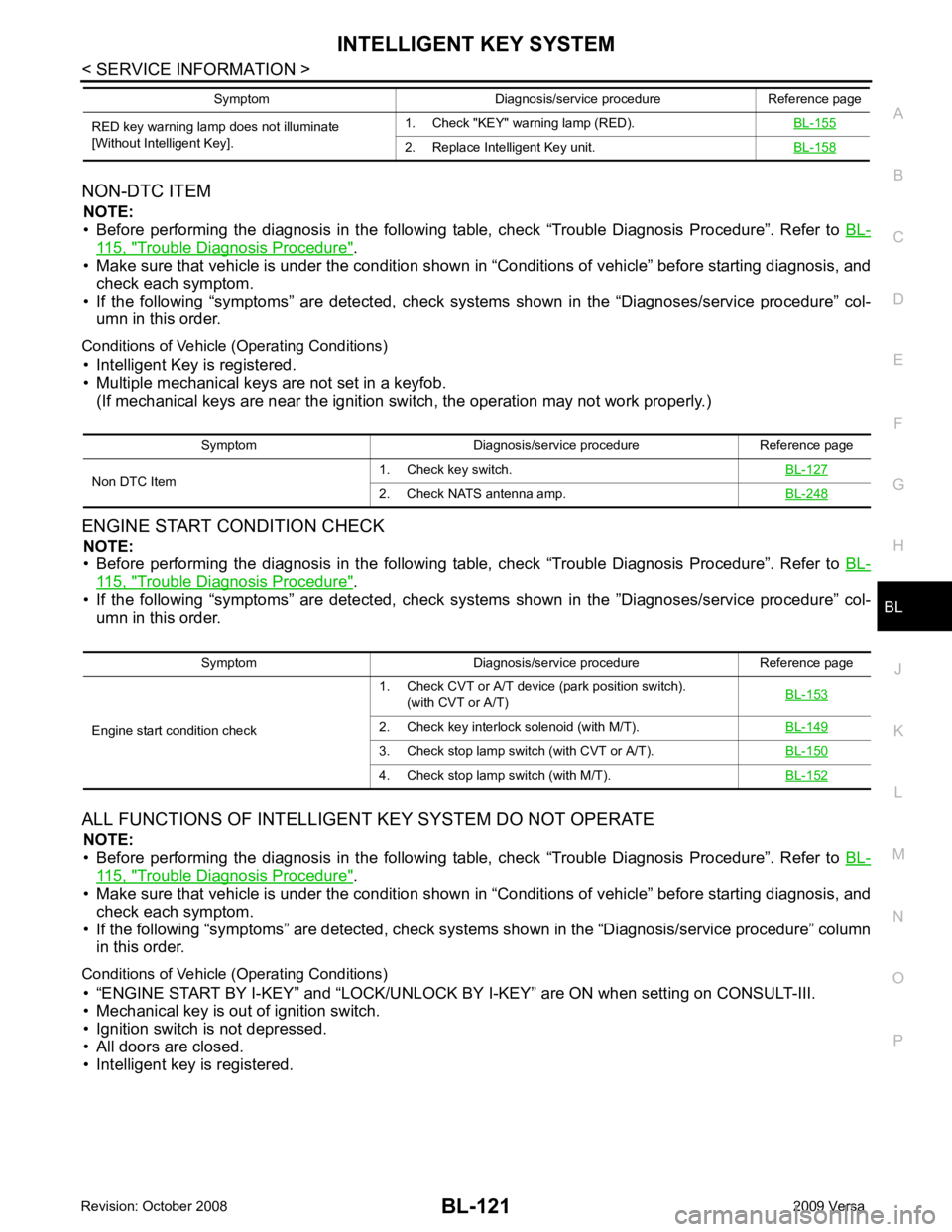
BL
N
O P
NON-DTC ITEM
NOTE:
• Before performing the diagnosis in the following table, check “Trouble Diagnosis Procedure”. Refer to BL-115, " Trouble Diagnosis Procedure " .
• Make sure that vehicle is under the condition shown in “Conditions of vehicle” before starting diagnosis, and
check each symptom.
• If the following “symptoms” are detected, check syst ems shown in the “Diagnoses/service procedure” col-
umn in this order.
Conditions of Vehicle (Operating Conditions) • Intelligent Key is registered.
• Multiple mechanical keys are not set in a keyfob. (If mechanical keys are near the ignition switch, the operation may not work properly.)
ENGINE START CONDITION CHECK NOTE:
• Before performing the diagnosis in the following table, check “Trouble Diagnosis Procedure”. Refer to BL-115, " Trouble Diagnosis Procedure " .
• If the following “symptoms” are detected, check syst ems shown in the ”Diagnoses/service procedure” col-
umn in this order.
ALL FUNCTIONS OF INTELLIGENT KEY SYSTEM DO NOT OPERATE
NOTE:
• Before performing the diagnosis in the following table, check “Trouble Diagnosis Procedure”. Refer to BL-115, " Trouble Diagnosis Procedure " .
• Make sure that vehicle is under the condition shown in “Conditions of vehicle” before starting diagnosis, and
check each symptom.
• If the following “symptoms” are detected, check syst ems shown in the “Diagnosis/service procedure” column
in this order.
Conditions of Vehicle (Operating Conditions) • “ENGINE START BY I-KEY” and “LOCK/UNLOCK BY I-KEY” are ON when setting on CONSULT-III.
• Mechanical key is out of ignition switch.
• Ignition switch is not depressed.
• All doors are closed.
• Intelligent key is registered. RED key warning lamp does not illuminate
[Without Intelligent Key]. 1. Check "KEY" warning lamp (RED).
BL-155 2. Replace Intelligent Key unit.
BL-158Symptom Diagnosis/service procedure Reference page
Symptom Diagnosis/service procedure Reference page
Non DTC Item 1. Check key switch.
BL-1272. Check NATS antenna amp.
BL-248Symptom Diagnosis/service procedure Reference page
Engine start condition check 1. Check CVT or A/T device (park position switch).
(with CVT or A/T) BL-153 2. Check key interlock solenoid (with M/T).
BL-1493. Check stop lamp switch (with CVT or A/T).
BL-1504. Check stop lamp switch (with M/T).
BL-152