2009 NISSAN TIIDA e control
[x] Cancel search: e controlPage 2373 of 4331

EC
NP
O
*1: 1st trip DTC No. is
the same as DTC No.
*2: This number is prescribed by SAE J2012.
*3: In Diagnostic Test Mode II (Self-diagnostic results), this number is controlled by NISSAN.
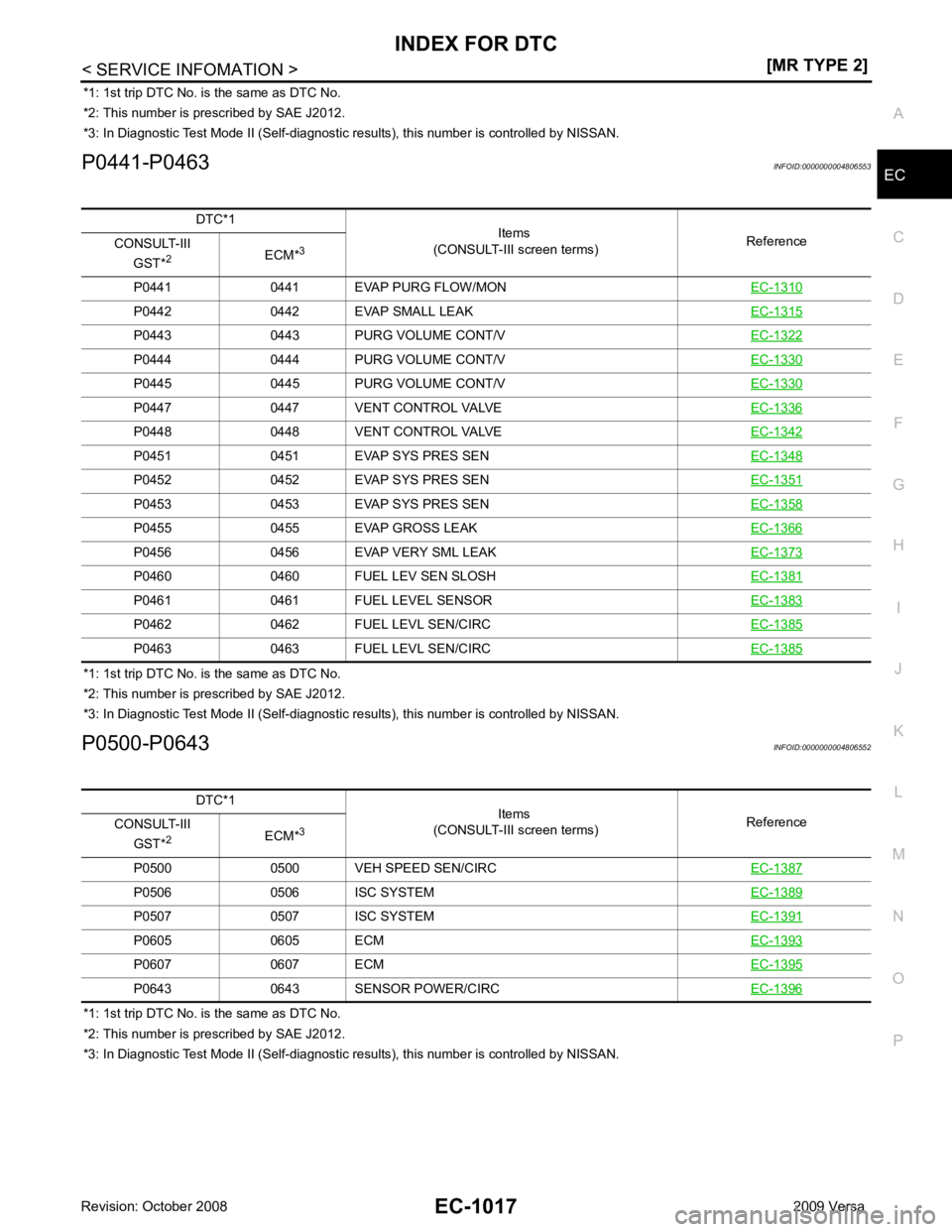
P0441-P0463 INFOID:0000000004806553
*1: 1st trip DTC No. is the same as DTC No.
*2: This number is prescribed by SAE J2012.
*3: In Diagnostic Test Mode II (Self-diagnostic results), this number is controlled by NISSAN.
P0500-P0643 INFOID:0000000004806552
*1: 1st trip DTC No. is the same as DTC No.
*2: This number is prescribed by SAE J2012.
*3: In Diagnostic Test Mode II (Self-diagnostic results), this number is controlled by NISSAN.
DTC*1
Items
(CONSULT-III screen terms) Reference
CONSULT-III
GST* 2
ECM*3
P0441 0441 EVAP PURG FLOW/MON EC-1310P0442 0442 EVAP SMALL LEAK
EC-1315P0443 0443 PURG VOLUME CONT/V
EC-1322P0444 0444 PURG VOLUME CONT/V
EC-1330P0445 0445 PURG VOLUME CONT/V
EC-1330P0447 0447 VENT CONTROL VALVE
EC-1336P0448 0448 VENT CONTROL VALVE
EC-1342P0451 0451 EVAP SYS PRES SEN
EC-1348P0452 0452 EVAP SYS PRES SEN
EC-1351P0453 0453 EVAP SYS PRES SEN
EC-1358P0455 0455 EVAP GROSS LEAK
EC-1366P0456 0456 EVAP VERY SML LEAK
EC-1373P0460 0460 FUEL LEV SEN SLOSH
EC-1381P0461 0461 FUEL LEVEL SENSOR
EC-1383P0462 0462 FUEL LEVL SEN/CIRC
EC-1385P0463 0463 FUEL LEVL SEN/CIRC
EC-1385DTC*1
Items
(CONSULT-III screen terms) Reference
CONSULT-III
GST* 2
ECM*3
P0500 0500 VEH SPEED SEN/CIRC EC-1387P0506 0506 ISC SYSTEM
EC-1389P0507 0507 ISC SYSTEM
EC-1391P0605 0605 ECM
EC-1393P0607 0607 ECM
EC-1395P0643 0643 SENSOR POWER/CIRC
EC-1396
Page 2375 of 4331

EC
NP
O
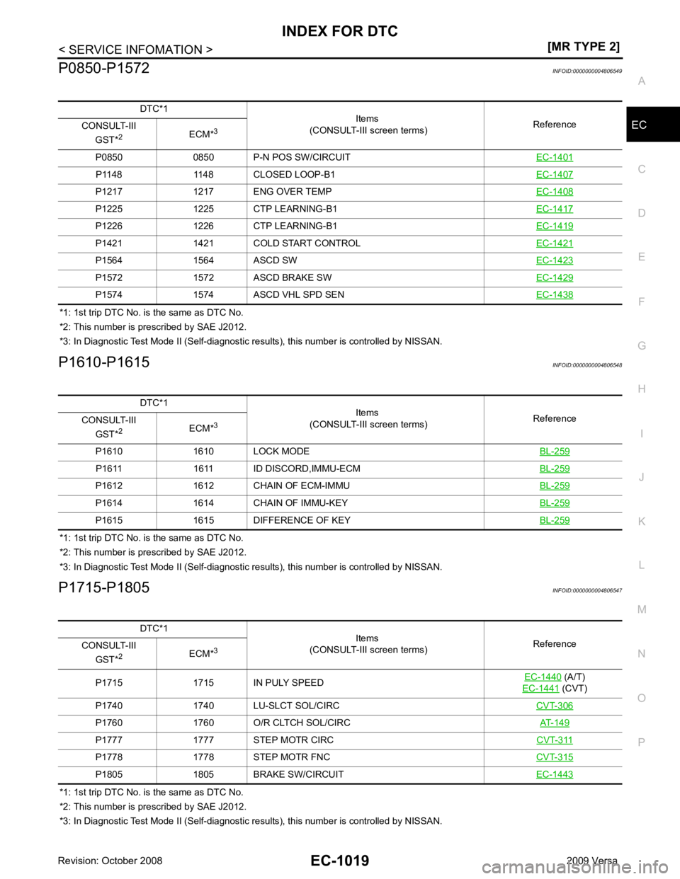
P0850-P1572
INFOID:0000000004806549
*1: 1st trip DTC No. is the same as DTC No.
*2: This number is prescribed by SAE J2012.
*3: In Diagnostic Test Mode II (Self-diagnostic results), this number is controlled by NISSAN.
P1610-P1615 INFOID:0000000004806548
*1: 1st trip DTC No. is the same as DTC No.
*2: This number is prescribed by SAE J2012.
*3: In Diagnostic Test Mode II (Self-diagnostic results), this number is controlled by NISSAN.
P1715-P1805 INFOID:0000000004806547
*1: 1st trip DTC No. is the same as DTC No.
*2: This number is prescribed by SAE J2012.
*3: In Diagnostic Test Mode II (Self-diagnostic results), this number is controlled by NISSAN.
DTC*1
Items
(CONSULT-III screen terms) Reference
CONSULT-III
GST* 2
ECM*3
P0850 0850 P-N POS SW/CIRCUIT EC-1401P1148 1148 CLOSED LOOP-B1
EC-1407P1217 1217 ENG OVER TEMP
EC-1408P1225 1225 CTP LEARNING-B1
EC-1417P1226 1226 CTP LEARNING-B1
EC-1419P1421 1421 COLD START CONTROL
EC-1421P1564 1564 ASCD SW
EC-1423P1572 1572 ASCD BRAKE SW
EC-1429P1574 1574 ASCD VHL SPD SEN
EC-1438DTC*1
Items
(CONSULT-III screen terms) Reference
CONSULT-III
GST* 2
ECM*3
P1610 1610 LOCK MODE BL-259P1611 1611 ID DISCORD,IMMU-ECM
BL-259P1612 1612 CHAIN OF ECM-IMMU
BL-259P1614 1614 CHAIN OF IMMU-KEY
BL-259P1615 1615 DIFFERENCE OF KEY
BL-259DTC*1
Items
(CONSULT-III screen terms) Reference
CONSULT-III
GST* 2
ECM*3
P1715 1715 IN PULY SPEED EC-1440 (A/T)
EC-1441 (CVT)
P1740 1740 LU-SLCT SOL/CIRC CVT-306P1760 1760 O/R CLTCH SOL/CIRC
AT-149P1777 1777 STEP MOTR CIRC
CVT-311P1778 1778 STEP MOTR FNC
CVT-315P1805 1805 BRAKE SW/CIRCUIT
EC-1443
Page 2378 of 4331
![NISSAN TIIDA 2009 Service Repair Manual EC-1022< SERVICE INFOMATION >
[MR TYPE 2]
PRECAUTIONS
• Be sure to connect rubber tubes properly afte r work. A misconnected or disconnected rubber tube
may cause the MIL to light up d NISSAN TIIDA 2009 Service Repair Manual EC-1022< SERVICE INFOMATION >
[MR TYPE 2]
PRECAUTIONS
• Be sure to connect rubber tubes properly afte r work. A misconnected or disconnected rubber tube
may cause the MIL to light up d](/manual-img/5/57398/w960_57398-2377.png)
EC-1022< SERVICE INFOMATION >
[MR TYPE 2]
PRECAUTIONS
• Be sure to connect rubber tubes properly afte r work. A misconnected or disconnected rubber tube
may cause the MIL to light up due to the malfunction of the fuel injection system, etc.
• Be sure to erase the unnecessary malfunction info rmation (repairs completed) from the ECM and
TCM (Transmission control module) before returning the vehicle to the customer.
Precaution INFOID:0000000004499902
• Always use a 12 volt battery as power source.
• Do not attempt to disconnect battery cables while engine is
running.
• Before connecting or disconnecting the ECM harness con-
nector, turn ignition switch OFF and disconnect negative bat-
tery cable. Failure to do so may damage the ECM because
battery voltage is applied to ECM even if ignition switch is
turned OFF.
• Before removing parts, turn ig nition switch OFF and then dis-
connect negative battery cable.
• Do not disassemble ECM.
• If battery cable is disconnected, the memory will return to the
initial ECM values.
The ECM will now start to self-c ontrol at its initial values.
Engine operation can vary slight ly in this case. However, this
is not an indication of a malf unction. Do not replace parts
because of a slight variation.
• If the battery is disconnected, the following emission-related
diagnostic information will be lost within 24 hours.
- Diagnostic trouble codes
- 1st trip diagnostic trouble codes
- Freeze frame data
- 1st trip freeze frame data
- System readiness test (SRT) codes
- Test values
• When connecting ECM harness connector, fasten (B) it
securely with a lever (1) as far as it will go as shown in the fig-
ure.
- ECM (2)
- Loosen (A)
• When connecting or disconnect ing pin connectors into or
from ECM, take care not to damage pin terminals (bend or
break).
Make sure that there are not any bends or breaks on ECM pin
terminal, when connecting pin connectors.
• Securely connect ECM harness connectors.
A poor connection can cause an extremely high (surge) volt-
age to develop in coil and co ndenser, thus resulting in dam-
age to ICs.
• Keep engine control system harness at least 10 cm (4 in) away
from adjacent harness, to preven t engine control system mal-
functions due to receiving exter nal noise, degraded operation
of ICs, etc. SEF289H
PBIA9222J
PBIB2947E
PBIB0090E
Page 2379 of 4331
![NISSAN TIIDA 2009 Service Repair Manual PRECAUTIONS
EC-1023
< SERVICE INFOMATION >
[MR TYPE 2] C
D E
F
G H
I
J
K L
M A EC
NP
O
•
Keep engine control system parts and harness dry.
• Before replacing ECM, perform “ECM Terminals an NISSAN TIIDA 2009 Service Repair Manual PRECAUTIONS
EC-1023
< SERVICE INFOMATION >
[MR TYPE 2] C
D E
F
G H
I
J
K L
M A EC
NP
O
•
Keep engine control system parts and harness dry.
• Before replacing ECM, perform “ECM Terminals an](/manual-img/5/57398/w960_57398-2378.png)
PRECAUTIONS
EC-1023
< SERVICE INFOMATION >
[MR TYPE 2] C
D E
F
G H
I
J
K L
M A EC
NP
O
•
Keep engine control system parts and harness dry.
• Before replacing ECM, perform “ECM Terminals and Refer-
ence Value” inspection and m ake sure ECM functions prop-
erly. Refer to EC-1109, " ECM Terminal and Reference Value " .
• Handle mass air flow sensor carefully to avoid damage.
• Do not disassemble mass air flow sensor.
• Do not clean mass air flow senso r with any type of detergent.
• Do not disassemble electric th rottle control actuator.
• Even a slight leak in the air intake system can cause serious
incidents.
• Do not shock or jar the camsh aft position sensor (PHASE),
crankshaft position sensor (POS).
• After performing each TROUBL E DIAGNOSIS, perform DTC
Confirmation Procedure or Overall Function Check.
The DTC should not be displ ayed in the DTC Confirmation
Procedure if the repair is completed. The Overall Function
Check should be a good result if the repair is completed.
• When measuring ECM signals with a circuit tester, never allow
the two tester probes to contact.
Accidental contact of probes will cause a short circuit and
damage the ECM power transistor.
• Do not use ECM ground termina ls when measuring input/out-
put voltage. Doing so may result in damage to the ECM's tran-
sistor. Use a ground other than ECM terminals, such as the
ground. MEF040D
SEF217U
SEF348N
Page 2380 of 4331
![NISSAN TIIDA 2009 Service Repair Manual EC-1024< SERVICE INFOMATION >
[MR TYPE 2]
PRECAUTIONS
• Do not operate fuel pump when there is no fuel in lines.
• Tighten fuel hose clamps to the specified torque.
- Fuel level sensor unit and NISSAN TIIDA 2009 Service Repair Manual EC-1024< SERVICE INFOMATION >
[MR TYPE 2]
PRECAUTIONS
• Do not operate fuel pump when there is no fuel in lines.
• Tighten fuel hose clamps to the specified torque.
- Fuel level sensor unit and](/manual-img/5/57398/w960_57398-2379.png)
EC-1024< SERVICE INFOMATION >
[MR TYPE 2]
PRECAUTIONS
• Do not operate fuel pump when there is no fuel in lines.
• Tighten fuel hose clamps to the specified torque.
- Fuel level sensor unit and fuel pump (1)
- Fuel pressure regulator (2)
- Fuel level sensor (3)
- Fuel tank temperature sensor (4)
• Do not depress accelerator pedal when starting.
• Immediately after starting, do not rev up engine unnecessar-
ily.
• Do not rev up engine just prior to shutdown.
• When installing C.B. ham radio or a mobile phone, be sure to
observe the following as it m ay adversely affect electronic
control systems depending on installation location.
- Keep the antenna as far as possi ble from the electronic con-
trol units.
- Keep the antenna feeder line more than 20 cm (8 in) away
from the harness of electronic controls.
Do not let them run parallel for a long distance.
- Adjust the antenna and feeder line so that the standing-wave
radio can be kept smaller.
- Be sure to ground the radio to vehicle body. BBIA0704E
SEF709Y
SEF708Y
Page 2383 of 4331

EC
NP
O
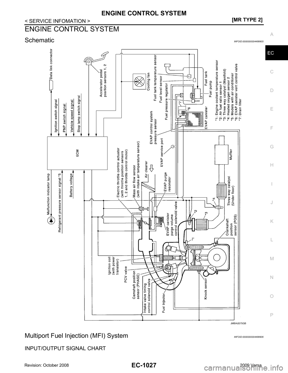
ENGINE CONTROL SYSTEM
Schematic INFOID:0000000004499905
Multiport Fuel Inje ction (MFI) System INFOID:0000000004499906
INPUT/OUTPUT SIGNAL CHART
Page 2384 of 4331
![NISSAN TIIDA 2009 Service Repair Manual EC-1028< SERVICE INFOMATION >
[MR TYPE 2]
ENGINE CONTROL SYSTEM
*1: This sensor is not used to control the engine system under normal conditions.
*2: This signal is sent to the ECM through CAN communi NISSAN TIIDA 2009 Service Repair Manual EC-1028< SERVICE INFOMATION >
[MR TYPE 2]
ENGINE CONTROL SYSTEM
*1: This sensor is not used to control the engine system under normal conditions.
*2: This signal is sent to the ECM through CAN communi](/manual-img/5/57398/w960_57398-2383.png)
EC-1028< SERVICE INFOMATION >
[MR TYPE 2]
ENGINE CONTROL SYSTEM
*1: This sensor is not used to control the engine system under normal conditions.
*2: This signal is sent to the ECM through CAN communication line.
*3: ECM determines the start signal status by the signals of engine speed and battery voltage.
SYSTEM DESCRIPTION
The amount of fuel injected from the fuel injector is determined by the ECM. The ECM controls the length of
time the valve remains open (injection pulse duration). T he amount of fuel injected is a program value in the
ECM memory. The program value is preset by engi ne operating conditions. These conditions are determined
by input signals (for engine speed and intake air) from t he crankshaft position sensor (POS), camshaft position
sensor (PHASE) and the ma ss air flow sensor.
VARIOUS FUEL INJECTION I NCREASE/DECREASE COMPENSATION
In addition, the amount of fuel injected is compens ated to improve engine performance under various operat-
ing conditions as listed below.
• During warm-up
• When starting the engine
• During acceleration
• Hot-engine operation
• When selector lever is changed from N to D (A/T and CVT models)
• High-load, high-speed operation
• During deceleration
• During high engine speed operation
MIXTURE RATIO FEEDBACK CONTROL (CLOSED LOOP CONTROL) Sensor Input Signal to ECM ECM function Actuator
Crankshaft position sensor (POS) Engine speed*3
Piston position
Fuel injection
& mixture ratio
control Fuel injector
Camshaft position sensor (PHASE)
Mass air flow sensor Amount of intake air
Engine coolant temperature sensor Engine coolant temperature
Air fuel ratio (A/F) sensor 1 Density of oxygen in exhaust gas
Throttle position sensor Throttle position
Accelerator pedal position sensor Accelerator pedal position
Park/neutral position (PNP) switch Gear position
Battery Battery voltage*3
Knock sensor Engine knocking condition
EPS control unit Power steering operation*2
Heated oxygen sensor 2* 1
Density of oxygen in exhaust gas
Air conditioner switch Air conditioner operation*2
ABS actuator and electric unit (control unit)
Vehicle speed*2
Combination meter PBIB3020E
Page 2385 of 4331
![NISSAN TIIDA 2009 Service Repair Manual ENGINE CONTROL SYSTEM
EC-1029
< SERVICE INFOMATION >
[MR TYPE 2] C
D E
F
G H
I
J
K L
M A EC
NP
O
The mixture ratio feedback system provides the best air/
fuel mixture ratio for drivability and emissio NISSAN TIIDA 2009 Service Repair Manual ENGINE CONTROL SYSTEM
EC-1029
< SERVICE INFOMATION >
[MR TYPE 2] C
D E
F
G H
I
J
K L
M A EC
NP
O
The mixture ratio feedback system provides the best air/
fuel mixture ratio for drivability and emissio](/manual-img/5/57398/w960_57398-2384.png)
ENGINE CONTROL SYSTEM
EC-1029
< SERVICE INFOMATION >
[MR TYPE 2] C
D E
F
G H
I
J
K L
M A EC
NP
O
The mixture ratio feedback system provides the best air/
fuel mixture ratio for drivability and emission control.
The three way catalyst (manifold) can then better r educe CO, HC and NOx emissions. This system uses air
fuel ratio (A/F) sensor 1 in the exhaust manifold to monitor whether the engine operation is rich or lean. The
ECM adjusts the injection pulse width according to the sensor voltage signal. For more information about air
fuel ratio (A/F) sensor 1, refer to EC-1210 . This maintains the mixture ratio within the range of stoichiometric
(ideal air/fuel mixture).
This stage is referred to as the closed loop control condition.
Heated oxygen sensor 2 is located downstream of the th ree way catalyst (manifold). Even if the switching
characteristics of air fuel ratio (A/F) sensor 1 shift, the air/fuel ratio is controlled to stoichiometric by the signal
from heated oxygen sensor 2.
Open Loop Control The open loop system condition refers to when the ECM detects any of the following conditions. Feedback
control stops in order to maintain stabilized fuel combustion.
• Deceleration and acceleration
• High-load, high-speed operation
• Malfunction of air fuel ratio (A/F) sensor 1 or its circuit
• Insufficient activation of air fuel ratio (A /F) sensor 1 at low engine coolant temperature
• High engine coolant temperature
• During warm-up
• After shifting from N to D (A/T and CVT models)
• When starting the engine
MIXTURE RATIO SELF-LEARNING CONTROL The mixture ratio feedback control system monitors the mixture ratio signal transmitted from air fuel ratio (A/F)
sensor 1. This feedback signal is then sent to the ECM. The ECM controls the basic mixture ratio as close to
the theoretical mixture ratio as possible. However, the bas ic mixture ratio is not necessarily controlled as orig-
inally designed. Both manufacturing differences (i.e., mass air flow sensor hot wire) and characteristic
changes during operation (i.e., fuel injector clogging) directly affect mixture ratio.
Accordingly, the difference between the basic and theoretical mixture ratios is monitored in this system. This is
then computed in terms of “injection pulse duration” to automatically compensate for the difference between
the two ratios.
“Fuel trim” refers to the feedback compensation value co mpared against the basic injection duration. Fuel trim
includes short term fuel trim and long term fuel trim.
“Short term fuel trim” is the short-term fuel compensati on used to maintain the mixture ratio at its theoretical
value. The signal from air fuel ratio (A/F) sensor 1 i ndicates whether the mixture ratio is RICH or LEAN com-
pared to the theoretical value. The signal then triggers a r eduction in fuel volume if the mixture ratio is rich, and
an increase in fuel volume if it is lean.
“Long term fuel trim” is overall fuel compensation ca rried out long-term to compensate for continual deviation
of the short term fuel trim from the central value. Such deviation will occur due to individual engine differences,
wear over time and changes in the usage environment.
FUEL INJECTION TIMING
Two types of systems are used.
Sequential Multiport Fuel Injection System
Fuel is injected into each cylinder during each engine cycl e according to the firing order. This system is used
when the engine is running.
Simultaneous Multiport Fuel Injection System Fuel is injected simultaneously into all four cylinders twice each engine cycle. In other words, pulse signals of
the same width are simultaneously transmitted from the ECM.
The four fuel injectors will then receive the signals two times for each engine cycle. SEF337W