2009 NISSAN TIIDA Ecm f11 connector
[x] Cancel search: Ecm f11 connectorPage 1683 of 4331
![NISSAN TIIDA 2009 Service Repair Manual P0453 EVAP CONTROL SYSTEM PRESSURE SENSOR
EC-327
< COMPONENT DIAGNOSIS >
[HR16DE] C
D E
F
G H
I
J
K L
M A EC
NP
O
12.
CHECK EVAP CONTROL SYSTEM PRESSURE SENS OR INPUT SIGNAL CIRCUIT FOR OPEN ANDSHORT
NISSAN TIIDA 2009 Service Repair Manual P0453 EVAP CONTROL SYSTEM PRESSURE SENSOR
EC-327
< COMPONENT DIAGNOSIS >
[HR16DE] C
D E
F
G H
I
J
K L
M A EC
NP
O
12.
CHECK EVAP CONTROL SYSTEM PRESSURE SENS OR INPUT SIGNAL CIRCUIT FOR OPEN ANDSHORT](/manual-img/5/57398/w960_57398-1682.png)
P0453 EVAP CONTROL SYSTEM PRESSURE SENSOR
EC-327
< COMPONENT DIAGNOSIS >
[HR16DE] C
D E
F
G H
I
J
K L
M A EC
NP
O
12.
CHECK EVAP CONTROL SYSTEM PRESSURE SENS OR INPUT SIGNAL CIRCUIT FOR OPEN ANDSHORT
1. Check the continuity between EVAP control syst em pressure sensor harness connector and ECM har-
ness connector.
2. Also check harness for short to ground and short to power.
Is the inspection result normal? YES >> GO TO 14.
NO >> GO TO 13. 13.
DETECT MALFUNCTIONING PART
Check the following.
• Harness connectors B102, M13
• Harness connectors M69, E7
• Harness connectors E8, F8
• Harness for open or short between EVAP c ontrol system pressure sensor and ECM
>> Repair open circuit or short to ground or short to power in harness or connectors. 14.
CHECK RUBBER TUBE
1. Disconnect rubber tube connected to EV AP canister vent control valve.
2. Check the rubber tube for clogging.
Is the inspection result normal? YES >> GO TO 15.
NO >> Clean the rubber tube using an air blower, repair or replace rubber tube. 15.
CHECK EVAP CANISTER VENT CONTROL VALVE
Refer to EC-304, " Component Inspection " .
Is the inspection result normal? YES >> GO TO 16.
NO >> Replace EVAP canister vent control valve. 16.
CHECK EVAP CONTROL SYSTEM PRESSURE SENSOR
Refer to EC-328, " Component Inspection " .
Is the inspection result normal? YES >> GO TO 17.
NO >> Replace EVAP control system pressure sensor. 17.
CHECK IF EVAP CANISTER IS SATURATED WITH WATER
1. Remove EVAP canister with EVAP canister vent c ontrol valve and EVAP control system pressure sensor
attached.
2. Check if water will drain from the EVAP canister.
Does water drain from EVAP canister? YES >> GO TO 18.
NO >> GO TO 20. EVAP control system pressure sensor ECM
Continuity
Connector Terminal Connector Terminal
B104 2 F11 42 Existed PBIB1213E
Page 1684 of 4331
![NISSAN TIIDA 2009 Service Repair Manual EC-328< COMPONENT DIAGNOSIS >
[HR16DE]
P0453 EVAP CONTROL SYSTEM PRESSURE SENSOR 18.
CHECK EVAP CANISTER
Weigh the EVAP canister with the EVAP canister vent control valve and EVAP control system pres NISSAN TIIDA 2009 Service Repair Manual EC-328< COMPONENT DIAGNOSIS >
[HR16DE]
P0453 EVAP CONTROL SYSTEM PRESSURE SENSOR 18.
CHECK EVAP CANISTER
Weigh the EVAP canister with the EVAP canister vent control valve and EVAP control system pres](/manual-img/5/57398/w960_57398-1683.png)
EC-328< COMPONENT DIAGNOSIS >
[HR16DE]
P0453 EVAP CONTROL SYSTEM PRESSURE SENSOR 18.
CHECK EVAP CANISTER
Weigh the EVAP canister with the EVAP canister vent control valve and EVAP control system pressure sensor
attached.
The weight should be less than 1.9 kg (4.2 lb).
Is the inspection result normal? YES >> GO TO 15.
NO >> GO TO 14. 19.
DETECT MALFUNCTIONING PART
Check the following.
• EVAP canister for damage
• EVAP hose between EVAP canister and vehicle frame for clogging or poor connection
>> Repair hose or replace EVAP canister. 20.
CHECK INTERMITTENT INCIDENT
Refer to EC-120, " Diagnosis Procedure " .
>> INSPECTION END
Component Inspection INFOID:00000000047804521.
CHECK EVAP CONTROL SY STEM PRESSURE SENSOR
1. Turn ignition switch OFF.
2. Remove EVAP control system pressure sensor wit h its harness connector connected from EVAP canister.
Always replace O-ring with a new one.
3. Install a vacuum pump to EVAP control system pressure sensor.
4. Turn ignition switch ON and check output voltage between ECM
harness connector and ground under the following conditions.
CAUTION:
• Always calibrate the vacuum pump gauge when using it.
• Do not apply below -93.3 kPa (-0.952 kg/cm 2
, -13.53 psi) or pressure over 101.3 kPa (1.033 kg/
cm 2
, 14.69 psi).
Is the inspection result normal? YES >> INSPECTION END
NO >> Replace EVAP control system pressure sensor ECM Condition
[Applied vacuum kPa
(kg/cm 2
, psi) Voltage
Connector Terminal
F11 42
(EVAP control system
pressure sensor signal) Not applied 1.8 - 4.8 V
-26.7 (-0.272, -3.87) 2.1 to 2.5 V lower
than above value PBIB3314E
Page 1719 of 4331

EC
NP
O
4. Check 1st trip DTC.
Is 1st trip DTC detected? YES >> Go to
EC-364, " Diagnosis Procedure " .
NO >> INSPECTION END Component Function Check " .
NOTE:
Use component function check the overal l function of the park/neutral position (PNP) switch circuit. During this
check, a 1st trip DTC might not be confirmed.
Is the inspection result normal? YES >> INSPECTION END
NO >> Go to EC-364, " Diagnosis Procedure " .
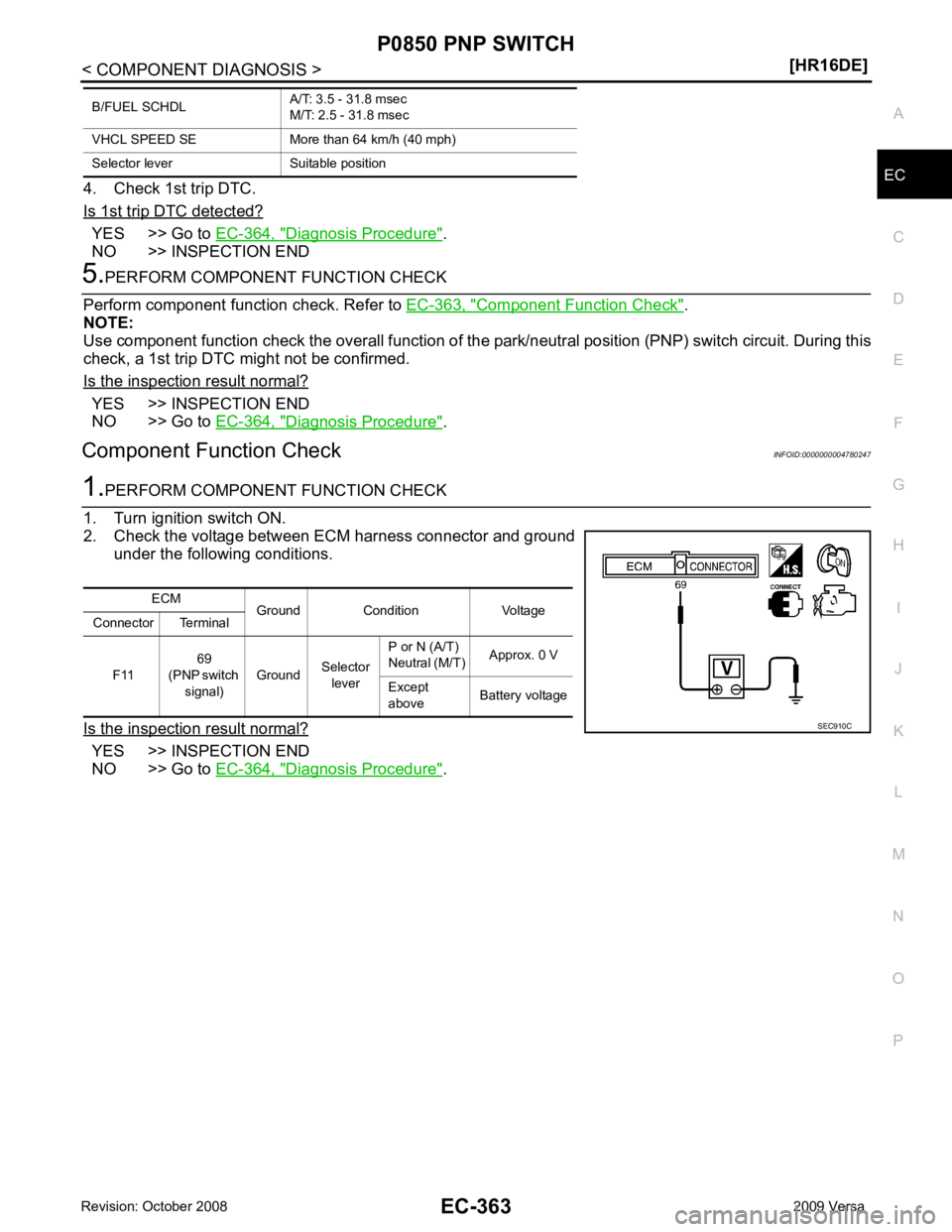
Component Function Check INFOID:0000000004780247YES >> INSPECTION END
NO >> Go to EC-364, " Diagnosis Procedure " .
B/FUEL SCHDL
A/T: 3.5 - 31.8 msec
M/T: 2.5 - 31.8 msec
VHCL SPEED SE More th an 64 km/h (40 mph)
Selector lever Suitable position ECM
Ground Condition Voltage
Connector Terminal
F11 69
(PNP switch
signal) Ground
Selector
lever P or N (A/T)
Neutral (M/T) Approx. 0 V
Except
above Battery voltage
Page 1761 of 4331

EC
NP
O
YES >> GO TO 2.
NO >> Repair or replace ground connection. YES >> GO TO 6.
NO >> GO TO 3. YES >> GO TO 4.
NO >> Repair open circuit or short to ground or short to power in harness or connectors. YES >> GO TO 5.
NO >> Repair short to ground or short to power in harness or connectors. Component Inspection " .)
• EVAP control system pressure sensor (Refer to EC-314, " Component Inspection " .)
• Refrigerant pressure sensor (Refer to EC-458, " Diagnosis Procedure " .)
Is the inspection result normal? YES >> GO TO 10.
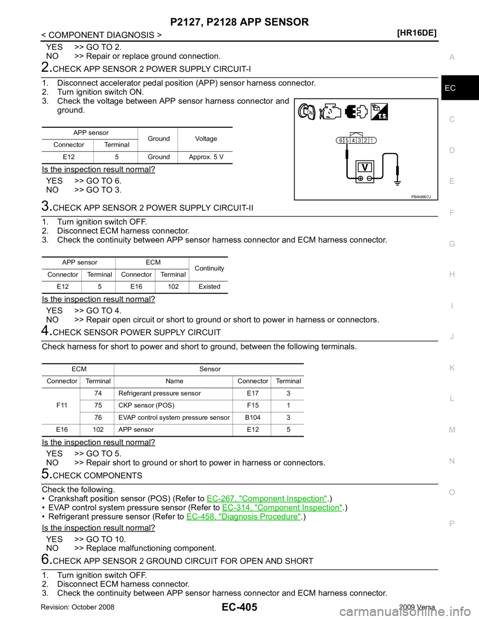
NO >> Replace malfunctioning component. ECM Sensor
Connector Terminal Name Connector Terminal
F11 74 Refrigerant pressure sensor E17 3
75 CKP sensor (POS) F15 1
76 EVAP control system pressure sensor B104 3
E16 102 APP sensor E12 5
Page 1766 of 4331
![NISSAN TIIDA 2009 Service Repair Manual EC-410< COMPONENT DIAGNOSIS >
[HR16DE]
P2135 TP SENSOR
YES >> GO TO 2.
NO >> Repair or replace ground connection. 2.
CHECK THROTTLE POSITION SE NSOR POWER SUPPLY CIRCUIT
1. Disconnect electric throttl NISSAN TIIDA 2009 Service Repair Manual EC-410< COMPONENT DIAGNOSIS >
[HR16DE]
P2135 TP SENSOR
YES >> GO TO 2.
NO >> Repair or replace ground connection. 2.
CHECK THROTTLE POSITION SE NSOR POWER SUPPLY CIRCUIT
1. Disconnect electric throttl](/manual-img/5/57398/w960_57398-1765.png)
EC-410< COMPONENT DIAGNOSIS >
[HR16DE]
P2135 TP SENSOR
YES >> GO TO 2.
NO >> Repair or replace ground connection. 2.
CHECK THROTTLE POSITION SE NSOR POWER SUPPLY CIRCUIT
1. Disconnect electric throttle control actuator harness connector.
2. Turn ignition switch ON.
3. Check the voltage between electric throttle control actuator har-
ness connector and ground.
Is the inspection result normal? YES >> GO TO 3.
NO >> Repair open circuit or short to ground or short to power
in harness or connectors. 3.
CHECK THROTTLE POSITION SENSOR GROUND CIRCUIT FOR OPEN AND SHORT
1. Turn ignition switch OFF.
2. Disconnect ECM harness connector.
3. Check the continuity between electric thro ttle control actuator harness connector and ground.
4. Also check harness for short to ground and short to power.
Is the inspection result normal? YES >> GO TO 4.
NO >> Repair open circuit or short to ground or short to power in harness or connectors. 4.
CHECK THROTTLE POSITION SENSOR INPUT SIGNAL CIRCUIT FOR OPEN AND SHORT
1. Check the continuity between electric thro ttle control actuator harness connector and ground.
2. Also check harness for short to ground and short to power.
Is the inspection result normal? YES >> GO TO 5.
NO >> Repair open circuit or short to ground or short to power in harness or connectors. 5.
CHECK THROTTLE POSITION SENSOR
Refer to EC-411, " Component Inspection " .
Is the inspection result normal? YES >> GO TO 7.
NO >> GO TO 6. 6.
REPLACE ELECTRIC THROTTLE CONTROL ACTUATOR
1. Replace electric throttle control actuator.
2. Perform EC-411, " Special Repair Requirement " .
>> INSPECTION END
Electric throttle control actuator
Ground Voltage
Connector Terminal
F7 2 Ground Approx. 5 V PBIB3311E
Electric throttle control actuator ECM
Continuity
Connector Terminal Connector Terminal
F7 4 F11 36 Existed Electric throttle control actuator ECM
Continuity
Connector Terminal Connector Terminal
F7 1
F1133
Existed
3 34
Page 1767 of 4331
![NISSAN TIIDA 2009 Service Repair Manual P2135 TP SENSOR
EC-411
< COMPONENT DIAGNOSIS >
[HR16DE] C
D E
F
G H
I
J
K L
M A EC
NP
O 7.
CHECK INTERMITTENT INCIDENT
Refer to EC-120, " Diagnosis Procedure " .
>> INSPECTION END
Component Inspectio NISSAN TIIDA 2009 Service Repair Manual P2135 TP SENSOR
EC-411
< COMPONENT DIAGNOSIS >
[HR16DE] C
D E
F
G H
I
J
K L
M A EC
NP
O 7.
CHECK INTERMITTENT INCIDENT
Refer to EC-120, " Diagnosis Procedure " .
>> INSPECTION END
Component Inspectio](/manual-img/5/57398/w960_57398-1766.png)
P2135 TP SENSOR
EC-411
< COMPONENT DIAGNOSIS >
[HR16DE] C
D E
F
G H
I
J
K L
M A EC
NP
O 7.
CHECK INTERMITTENT INCIDENT
Refer to EC-120, " Diagnosis Procedure " .
>> INSPECTION END
Component Inspection INFOID:00000000047804491.
CHECK THROTTLE POSITION SENSOR
1. Turn ignition switch OFF.
2. Reconnect all harness connectors disconnected.
3. Perform EC-411, " Special Repair Requirement " .
4. Turn ignition switch ON.
5. Set selector lever to D (A/T) or 1st (M/T) position.
6. Check the voltage between ECM harness connector and
ground.
Is the inspection result normal? YES >> INSPECTION END
NO >> GO TO 2. 2.
REPLACE ELECTRIC THROTTLE CONTROL ACTUATOR
1. Replace electric throttle control actuator.
2. Perform EC-411, " Special Repair Requirement " .
>> INSPECTION END
Special Repair Requirement INFOID:00000000047804501.
PERFORM THROTTLE VALVE CL OSED POSITION LEARNING
Refer to EC-31, " THROTTLE VALVE CLOSED POSITION L
EARNING : Special Repair Requirement "
>> GO TO 2.
2.
PERFORM IDLE AIR VOLUME LEARNING
Refer to EC-32, " IDLE AIR VOLUME LEARNING : Special Repair Requirement "
>> ENDECM
Ground Condition Voltage
Connector Terminal
F11 33
(TP sensor
1 signal)
GroundAccelerator
pedal Fully released
More than
0.36V
Fully de-
pressed Less than
4.75V
34
(TP sensor 2 signal) Fully released
Less than
4.75V
Fully de-
pressed More than
0.36V PBIB3038E
Page 1770 of 4331
![NISSAN TIIDA 2009 Service Repair Manual EC-414< COMPONENT DIAGNOSIS >
[HR16DE]
P2138 APP SENSOR
YES >> GO TO 2.
NO >> Repair or replace ground connection. 2.
CHECK APP SENSOR 1 POWER SUPPLY CIRCUIT
1. Disconnect accelerator pedal position ( NISSAN TIIDA 2009 Service Repair Manual EC-414< COMPONENT DIAGNOSIS >
[HR16DE]
P2138 APP SENSOR
YES >> GO TO 2.
NO >> Repair or replace ground connection. 2.
CHECK APP SENSOR 1 POWER SUPPLY CIRCUIT
1. Disconnect accelerator pedal position (](/manual-img/5/57398/w960_57398-1769.png)
EC-414< COMPONENT DIAGNOSIS >
[HR16DE]
P2138 APP SENSOR
YES >> GO TO 2.
NO >> Repair or replace ground connection. 2.
CHECK APP SENSOR 1 POWER SUPPLY CIRCUIT
1. Disconnect accelerator pedal position (APP) sensor harness connector.
2. Turn ignition switch ON.
3. Check the voltage between APP sensor harness connector and
ground.
Is the inspection result normal? YES >> GO TO 3.
NO >> Repair open circuit or short to ground or shot to power in
harness or connectors. 3.
CHECK APP SENSOR 2 POWER SUPPLY CIRCUIT-I
1. Check the voltage between APP sensor harness connector and ground.
Is the inspection result normal? YES >> GO TO 7.
NO >> GO TO 4. 4.
CHECK APP SENSOR 2 POWER SUPPLY CIRCUIT-II
1. Turn ignition switch OFF.
2. Disconnect ECM harness connector.
3. Check the continuity between APP sens or harness connector and ECM harness connector.
Is the inspection result normal? YES >> GO TO 5.
NO >> Repair open circuit or short to ground or shot to power in harness or connectors. 5.
CHECK SENSOR POWER SUPPLY CIRCUIT
Check harness for short to power and short to ground, between the following terminals.
Is the inspection result normal? YES >> GO TO 6.
NO >> Repair short to ground or short to power in harness or connectors. APP sensor
Ground Voltage
Connector Terminal
E12 4 Ground Approx. 5 V PBIA9606J
APP sensor
Ground Voltage
Connector Terminal
E12 5 Ground Approx. 5 V PBIA9607J
APP sensor ECM
Continuity
Connector Terminal Connector Terminal
E12 4 E16 106 Existed ECM Sensor
Connector Terminal Name Connector Terminal
F11 74 Refrigerant pressure sensor E17 3
75 CKP sensor (POS) F15 1
76 EVAP control system pressure sensor B104 3
E16 102 APP sensor E12 5
Page 1815 of 4331

EC
NP
O
4. Check ground connections E15, E24. Refer to
EC-125, " Ground Inspection " .
Is the inspection result normal? YES >> GO TO 2.
NO >> Repair or replace ground connection. YES >> GO TO 4.
NO >> GO TO 3. YES >> GO TO 6.
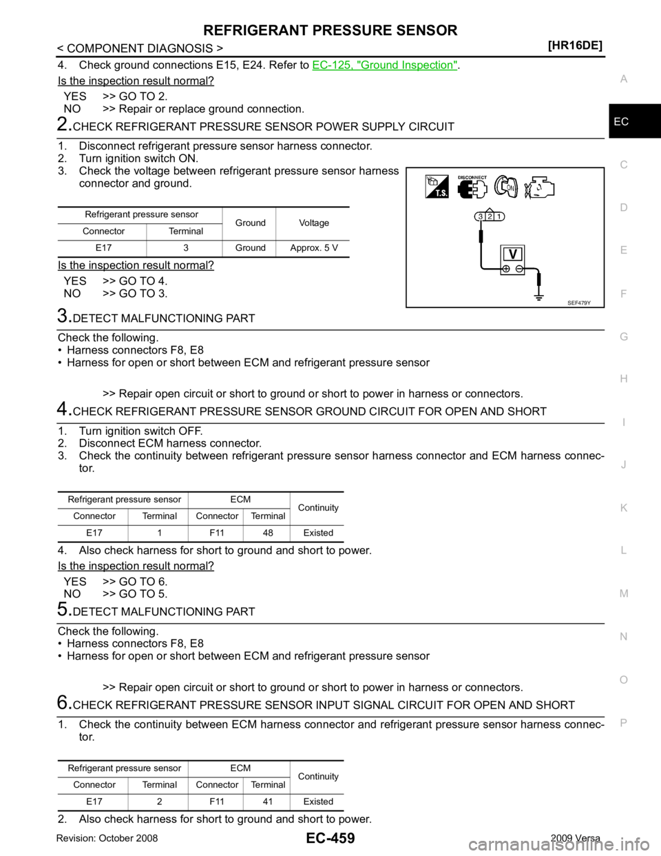
NO >> GO TO 5. Refrigerant pressure sensor ECM
Continuity
Connector Terminal Connector Terminal
E17 2 F11 41 Existed