2009 NISSAN TIIDA Cooler
[x] Cancel search: CoolerPage 1300 of 4331
![NISSAN TIIDA 2009 Service Repair Manual CVT-356< SERVICE INFORMATION >
[RE0F08B]
TRANSAXLE ASSEMBLY
• When installing the cooler outlet tube (1) to the transaxle assembly (2), align the cooler tube bracket (A) against the transax](/manual-img/5/57398/w960_57398-1299.png "NISSAN TIIDA 2009 Service Repair Manual CVT-356< SERVICE INFORMATION >
[RE0F08B]
TRANSAXLE ASSEMBLY
• When installing the cooler outlet tube (1) to the transaxle assembly (2), align the cooler tube bracket (A) against the transax")
CVT-356< SERVICE INFORMATION >
[RE0F08B]
TRANSAXLE ASSEMBLY
• When installing the cooler outlet tube (1) to the transaxle assembly (2), align the cooler tube bracket (A) against the transaxle as
shown.
• When installing the transaxle to the engine, align t he matching mark on the drive plate with the matching
mark on the torque converter alignment stud.
• When securing the transaxle to the engine, attach the bolts in
accordance with the following standard.
• When installing the drive plate to torque converter nuts, tighten them temporarily. Then tighten the nuts to the specified torque.
• After completing installation check for fluid level, fluid leakage, and the positions of CVT. Refer to CVT-196," Checking CVT Fluid " ,
CVT-345, " Adjustment of CVT Position " and
CVT-345, " Checking of CVT Position " .
• When replacing the CVT assembly, erase EEP ROM in TCM. Refer to CVT-190, " Service After Replacing
TCM and Transaxle Assembly " . WCIA0618E
Bolt No. 1 (Transaxle to engine) 2 (Engine to transaxle)
Number of bolts 2 7
Bolt length
“A” mm (in) 55 (2.17) 50 (1.97)
Tightening torque
N·m (kg-m, ft-lb) 62 (6.3, 46) WCIA0619E
Converter nuts: : 51 N·m (5.2 kg-m, 38 ft-lb)
WCIA0616E
Page 1846 of 4331

Camshaft
EM-58Intake valve timing control
EM-49Intake valve
3EM-82 Exhaust valve
Exhaust Exhaust manifold/Tube/Muf- fler/Gasket 5 5 5 5 5 5 5 5 EM-31 EX-4
Three way catalyst
Lubrica-
tion Oil pan/Oil strainer/Oil pump/ Oil filter/Oil gallery/Oil cooler 5 5 5 5 5 5 5 5 EM-39 EM-42
LU-7
LU-9
Oil level (Low)/Filthy oil
LU-7Cooling Radiator/Hose/Radiator filler
cap
5 5 5 5 5 5 5 4 5 CO-14 CO-14
Thermostat 5
CO-23Water pump
CO-21Water gallery
CO-9Cooling fan
5CO-19Coolant level (Low)/Contami-
nated coolant CO-9NVIS (NISSAN Vehicle Immobilizer Sys-
tem — NATS) 1 1
BL-257 SYMPTOM
Reference pageHARD/NO START/RESTART (EXCP. HA)
ENGINE STALL
HESITATION/SURGING/FLAT SPOT
SPARK KNOCK/DETONATION
LACK OF POWER/POOR ACCELERATION
HIGH IDLE/LOW IDLE
ROUGH IDLE/HUNTING
IDLING VIBRATION
SLOW/NO RETURN TO IDLE
OVERHEATS/WATER TEMPERATURE HIGH
EXCESSIVE FUEL CONSUMPTION
EXCESSIVE OIL CONSUMPTION
BATTERY DEAD (UNDER CHARGE)
Warranty symptom code A AAB AC AD AE AF AG AH AJ AK AL AM HA
Page 3037 of 4331
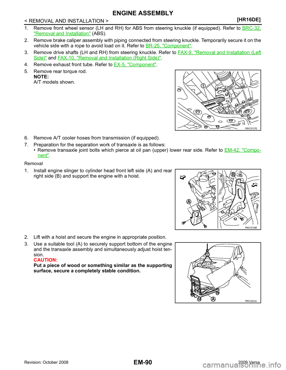
" Removal and Installation " (ABS).
2. Remove brake caliper assembly with piping connected fr om steering knuckle. Temporarily secure it on the
vehicle side with a rope to avoid load on it. Refer to BR-25, " Component " .
3. Remove drive shafts (LH and RH) from steering knuckle. Refer to FAX-9, " Removal and Installation (Left
Side) " and
FAX-10, " Removal and Installation (Right Side) " .
4. Remove exhaust front tube. Refer to EX-5, " Component " .
5. Remove rear torque rod. NOTE:
A/T models shown.
6. Remove A/T cooler hoses from transmission (if equipped).
7. Preparation for the separation work of transaxle is as follows: • Remove transaxle joint bolts which pierce at oil pan (upper) lower rear side. Refer to EM-42, " Compo-
nent " .
Removal
1. Install engine slinger to cylinder head front left side (A) and rear right side (B) and support the engine with a hoist.
2. Lift with a hoist and secure the engine in appropriate position.
3. Use a suitable tool (A) to securely support bottom of the engine and the transaxle assembly and simultaneously adjust hoist ten-
sion.
CAUTION:
Put a piece of wood or someth ing similar as the supporting
surface, secure a completely stable condition. PBIC3223J
Page 3143 of 4331
Garage Jack and
Safety Stand and 2-Pole Lift " .
REMOVAL
Remove the engine and the transaxle assembly from t he vehicle downward. Separate the engine and the tran-
saxle.
1. Remove engine undercover.
2. Drain engine coolant from radiator. Refer to CO-35, " Changing Engine Coolant " .
CAUTION:
• Perform this step when the engine is cold.
• Do not spill engine coolant on drive belt.
3. Remove front fender protector (RH and LH). Refer to EI-24 .
4. Remove exhaust front tube. Refer to EX-9 .
5. Remove drive shafts (LH and RH) from steering knuckle. Refer to FAX-9 .
6. Remove transaxle joint bolts which pierce at oil pan (upper) lower rear side. Refer to AT-232 (A/T models),
CVT-182 or
CVT-354 (CVT models) or
MT-58 (M/T models).
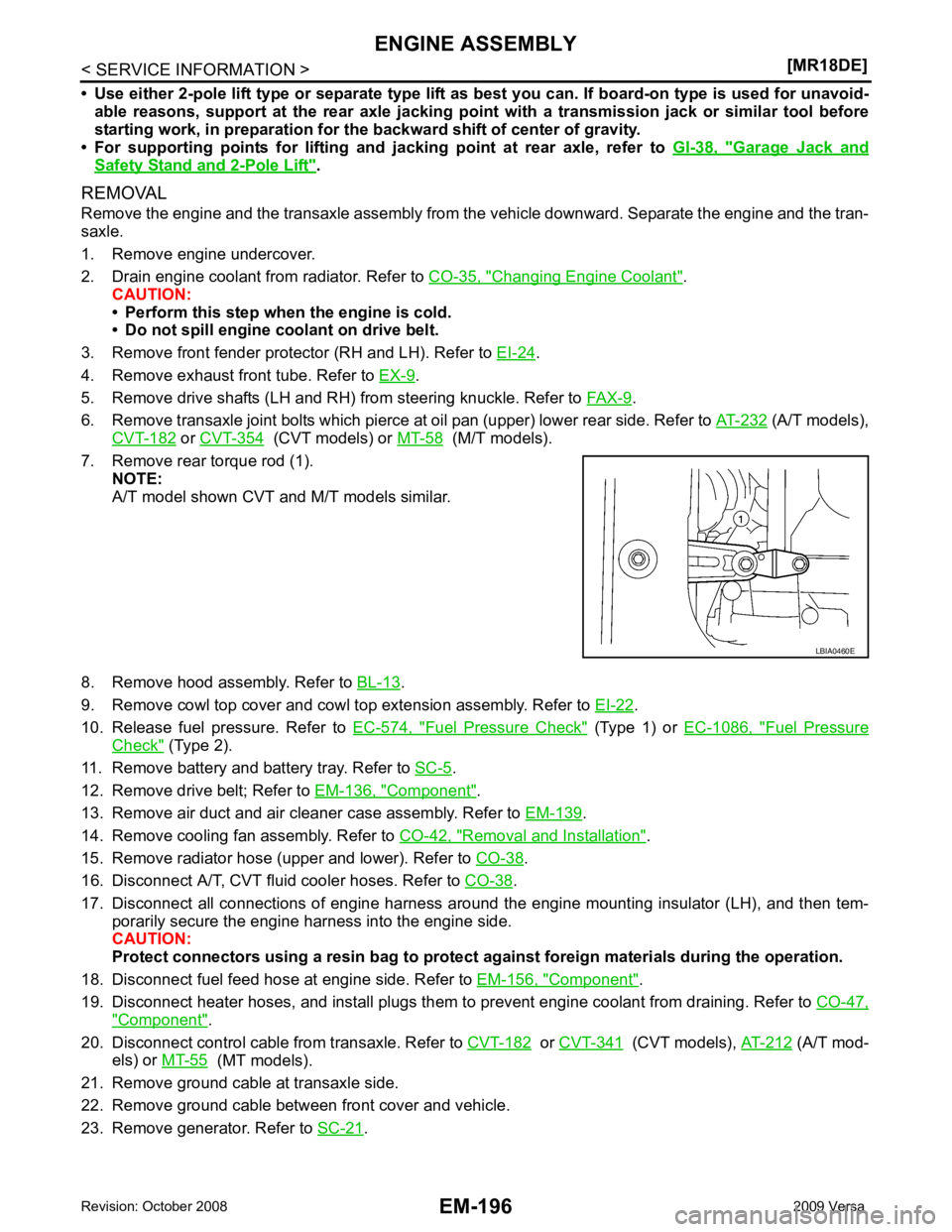
7. Remove rear torque rod (1). NOTE:
A/T model shown CVT and M/T models similar.
8. Remove hood assembly. Refer to BL-13 .
9. Remove cowl top cover and cowl top extension assembly. Refer to EI-22 .
10. Release fuel pressure. Refer to EC-574, " Fuel Pressure Check " (Type 1) or
EC-1086, " Fuel Pressure
Check " (Type 2).
11. Remove battery and battery tray. Refer to SC-5 .
12. Remove drive belt; Refer to EM-136, " Component " .
13. Remove air duct and air cleaner case assembly. Refer to EM-139 .
14. Remove cooling fan assembly. Refer to CO-42, " Removal and Installation " .
15. Remove radiator hose (upper and lower). Refer to CO-38 .
16. Disconnect A/T, CVT fluid cooler hoses. Refer to CO-38 .
17. Disconnect all connections of engine harness around the engine mounting insulator (LH), and then tem- porarily secure the engine harness into the engine side.
CAUTION:
Protect connectors using a resin bag to protect against foreign materials during the operation.
18. Disconnect fuel feed hose at engine side. Refer to EM-156, " Component " .
19. Disconnect heater hoses, and install plugs them to prevent engine coolant from draining. Refer to CO-47," Component " .
20. Disconnect control cable from transaxle. Refer to CVT-182 or
CVT-341 (CVT models),
AT-212 (A/T mod-
els) or MT-55 (MT models).
21. Remove ground cable at transaxle side.
22. Remove ground cable between front cover and vehicle.
23. Remove generator. Refer to SC-21 .
Page 3300 of 4331

GI
N
O P
TERMINOLOGY
SAE J1930 Terminology List INFOID:0000000004307379
All emission related terms used in this publication in accordance with SAE J1930 are listed. Accordingly, new
terms, new acronyms/abbreviations and old terms are listed in the following chart.
NEW TERM NEW ACRONYM /
ABBREVIATION OLD TERM
Air cleaner ACL Air cleaner
Barometric pressure BARO ***
Barometric pressure se nsor-BCDD BAROS-BCDD BCDD
Camshaft position CMP ***
Camshaft position sensor CMPS Crank angle sensor
Canister *** Canister
Carburetor CARB Carburetor
Charge air cooler CAC Intercooler
Closed loop CL Closed loop
Closed throttle position switch CTP switch Idle switch
Clutch pedal position switch CPP switch Clutch switch
Continuous fuel injection system CFI system ***
Continuous trap oxidizer system CTOX system ***
Crankshaft position CKP ***
Crankshaft position sensor CKPS ***
Data link connector DLC ***
Data link connector fo r CONSULT-III DLC for CONSULT-III Di agnostic connector for CONSULT-III
Diagnostic test mode DTM Diagnostic mode
Diagnostic test mode selector DTM selector Diagnostic mode selector
Diagnostic test mode I DTM I Mode I
Diagnostic test mode II DTM II Mode II
Diagnostic trouble code DTC Malfunction code
Direct fuel injection system DFI system ***
Distributor ignition system DI system Ignition timing control
Early fuel evaporation-mixture heater EFE-mixture heater Mixture heater
Early fuel evaporation system EFE system Mixture heater control
Electrically erasable programmable read
only memory EEPROM ***
Electronic ignition system EI system Ignition timing control
Engine control EC ***
Engine control module ECM ECCS control unit
Engine coolant temperature ECT Engine temperature
Engine coolant temperature sensor ECTS Engine temperature sensor
Engine modification EM ***
Engine speed RPM Engine speed
Erasable programmable read only memory EPROM ***
Evaporative emission canister EVAP canister Canister
Evaporative emission system EVAP system Canister control solenoid valve
Exhaust gas recirculation valve EGR valve EGR valve
Page 3782 of 4331
CHASSIS AND BODY MAINTENANCE
MA-39
< SERVICE INFORMATION >
C
D E
F
G H
I
J
K
M A
B MA
N
O P
CVT FLUID : Changing CVT Fluid (RE0F08A)
INFOID:0000000004803427
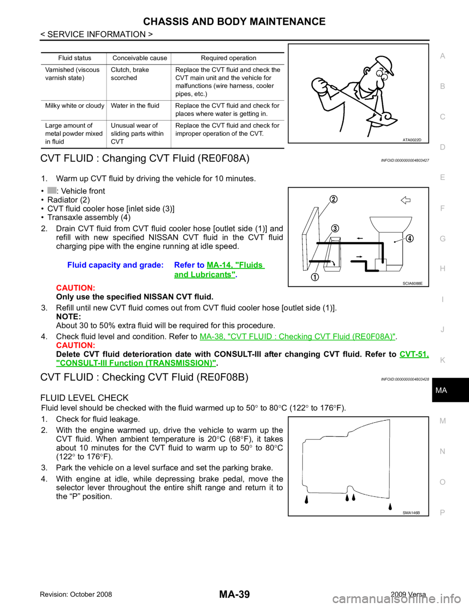
1. Warm up CVT fluid by driving the vehicle for 10 minutes.
• : Vehicle front
• Radiator (2)
• CVT fluid cooler hose [inlet side (3)]
• Transaxle assembly (4)
2. Drain CVT fluid from CVT fluid cooler hose [outlet side (1)] and refill with new specified NISSAN CVT fluid in the CVT fluid
charging pipe with the engine running at idle speed.
CAUTION:
Only use the specifi ed NISSAN CVT fluid.
3. Refill until new CVT fluid comes out from CVT fluid cooler hose [outlet side (1)]. NOTE:
About 30 to 50% extra fluid will be required for this procedure.
4. Check fluid level and condition. Refer to MA-38, " CVT FLUID : Checking CVT Fluid (RE0F08A) " .
CAUTION:
Delete CVT fluid deterioration date with CONSULT-III after changing CVT fluid. Refer to CVT-51," CONSULT-III Function (TRANSMISSION) " .
CVT FLUID : Checking CVT Fluid (RE0F08B) INFOID:0000000004803428
FLUID LEVEL CHECK Fluid level should be checked with the fluid warmed up to 50 ° to 80 °C (122 ° to 176 °F).
1. Check for fluid leakage.
2. With the engine warmed up, drive the vehicle to warm up the CVT fluid. When ambient temperature is 20 °C (68 °F), it takes
about 10 minutes for the CVT fluid to warm up to 50 ° to 80 °C
(122 ° to 176 °F).
3. Park the vehicle on a level surface and set the parking brake.
4. With engine at idle, while depressing brake pedal, move the selector lever throughout the entire shift range and return it to
the “P” position. Fluid status Conceivable cause Required operation
Varnished (viscous
varnish state) Clutch, brake
scorched Replace the CVT fluid and check the
CVT main unit and the vehicle for
malfunctions (wire harness, cooler
pipes, etc.)
Milky white or cloudy Water in the fluid Replace the CVT fluid and check for places where water is getting in.
Large amount of
metal powder mixed
in fluid Unusual wear of
sliding parts within
CVT Replace the CVT fluid and check for
improper operation of the CVT. ATA0022D
Fluid capacity and grade: Refer to
MA-14, " Fluids
and Lubricants " .
SCIA6088E
SMA146B
Page 3783 of 4331
MA-40< SERVICE INFORMATION >
CHASSIS AND BODY MAINTENANCE
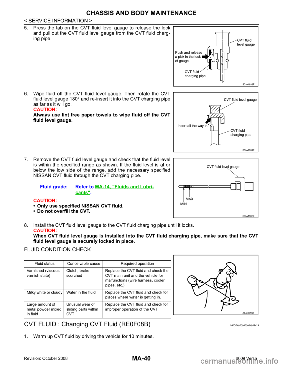
5. Press the tab on the CVT fluid level gauge to release the lock and pull out the CVT fluid level gauge from the CVT fluid charg-
ing pipe.
6. Wipe fluid off the CVT fluid level gauge. Then rotate the CVT fluid level gauge 180 ° and re-insert it into the CVT charging pipe
as far as it will go.
CAUTION:
Always use lint free paper towels to wipe fluid off the CVT
fluid level gauge.
7. Remove the CVT fluid level gauge and check that the fluid level is within the specified range as shown. If the fluid level is at or
below the low side of the range, add the necessary specified
NISSAN CVT fluid through the CVT charging pipe.
CAUTION:
• Only use specified NISSAN CVT fluid.
• Do not overfill the CVT.
8. Install the CVT fluid level gauge to the CVT fluid charging pipe until it locks. CAUTION:
When CVT fluid level gauge is in stalled into the CVT fluid charging pipe, make sure that the CVT
fluid level gauge is securely locked in place.
FLUID CONDITION CHECK
CVT FLUID : Changing CVT Fluid (RE0F08B) INFOID:0000000004803429
1. Warm up CVT fluid by driving the vehicle for 10 minutes. SCIA1933E
SCIA1931E
Fluid grade: Refer to
MA-14, " Fluids and Lubri-
cants " .
SCIA1932E
Fluid status Conceivable cause Required operation
Varnished (viscous
varnish state) Clutch, brake
scorched Replace the CVT fluid and check the
CVT main unit and the vehicle for
malfunctions (wire harness, cooler
pipes, etc.)
Milky white or cloudy Water in the fluid Replace the CVT fluid and check for places where water is getting in.
Large amount of
metal powder mixed
in fluid Unusual wear of
sliding parts within
CVT Replace the CVT fluid and check for
improper operation of the CVT. ATA0022D
Page 3784 of 4331
![NISSAN TIIDA 2009 Service Repair Manual CHASSIS AND BODY MAINTENANCE
MA-41
< SERVICE INFORMATION >
C
D E
F
G H
I
J
K
M A
B MA
N
O P
• : Vehicle front
• Radiator (2)
• CVT fluid cooler hose [inlet side (3)]
• Transaxle assembly (4)
2](/manual-img/5/57398/w960_57398-3783.png "NISSAN TIIDA 2009 Service Repair Manual CHASSIS AND BODY MAINTENANCE
MA-41
< SERVICE INFORMATION >
C
D E
F
G H
I
J
K
M A
B MA
N
O P
• : Vehicle front
• Radiator (2)
• CVT fluid cooler hose [inlet side (3)]
• Transaxle assembly (4)
2")
CHASSIS AND BODY MAINTENANCE
MA-41
< SERVICE INFORMATION >
C
D E
F
G H
I
J
K
M A
B MA
N
O P
• : Vehicle front
• Radiator (2)
• CVT fluid cooler hose [inlet side (3)]
• Transaxle assembly (4)
2. Drain CVT fluid from CVT fluid cooler hose [outlet side (1)] and refill with new specified NISSAN CVT fluid in the CVT fluid
charging pipe with the engine running at idle speed.
CAUTION:
Only use the specifi ed NISSAN CVT fluid.
3. Refill until new CVT fluid comes out from CVT fluid cooler hose [outlet side (1)]. NOTE:
About 30 to 50% extra fluid will be required for this procedure.
4. Check fluid level and condition. Refer to MA-39, " CVT FLUID : Checking CVT Fluid (RE0F08B) " .
CAUTION:
Delete CVT fluid deterioration date with CO NSULT-III after changing CVT fluid. Refer to CVT-230," CONSULT-III Function (TRANSMISSION) " .
CLUTCH FLUID
CLUTCH FLUID : Air Bleeding Procedure INFOID:0000000004683730
CAUTION:
Do not spill clutch fluid onto painted surfaces. If it spills, wipe up immediately and wash the affected
area with water.
NOTE:
• Do not use a vacuum assist or any other type of pow er bleeder on this system. Use of a vacuum assist or
power bleeder will not purge all the air from the system.
• Carefully monitor fluid level in reservoir tank during bleeding operation.
1. Fill master cylinder reservoir tank with new clutch fluid.
2. Connect a transparent vinyl tube and container to the bleeding connector (1) on the CSC.
3. Depress and release the clutch pedal slowly and fully 15 times at an interval of two to three seconds and release the clutch
pedal.
4. Push in the lock pin (1) of the bleeding connector (2), and maintain the position. • RS5F91R transaxle models
CAUTION:
Hold the lock pin in to preven t the bleeding connector from
separating when fluid pressure is applied.
Fluid capacity and grade: Refer to
MA-14, " Fluids
and Lubricants " .
SCIA6088E
PCIB1494E
PCIB1495E