2009 NISSAN TIIDA Cooler
[x] Cancel search: CoolerPage 226 of 4331
AT
N
O P
ON-VEHICLE SERVICE
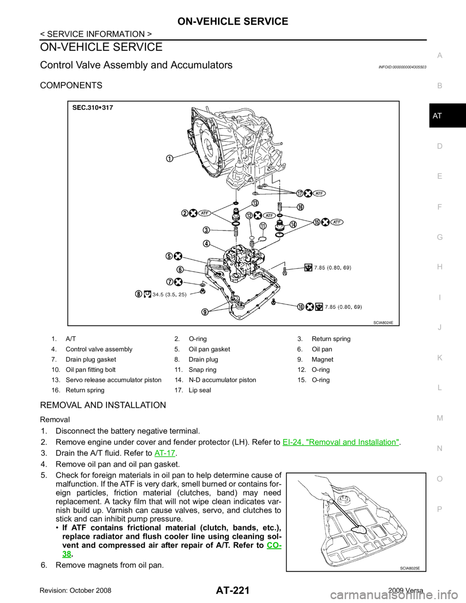
Control Valve Assembly and Accumulators INFOID:0000000004305503
COMPONENTS
REMOVAL AND INSTALLATION
Removal 1. Disconnect the battery negative terminal.
2. Remove engine under cover and fender protector (LH). Refer to EI-24, " Removal and Installation " .
3. Drain the A/T fluid. Refer to AT-17 .
4. Remove oil pan and oil pan gasket.
5. Check for foreign materials in oil pan to help determine cause of malfunction. If the ATF is very dark, smell burned or contains for-
eign particles, friction material (clutches, band) may need
replacement. A tacky film that will not wipe clean indicates var-
nish build up. Varnish can cause valves, servo, and clutches to
stick and can inhibit pump pressure.
• If ATF contains frictional material (clutch, bands, etc.),
replace radiator and flush cooler line using cleaning sol-
vent and compressed air after repair of A/T. Refer to CO-38 .
6. Remove magnets from oil pan. 1. A/T 2. O-ring 3. Return spring
4. Control valve assembly 5. Oil pan gasket 6. Oil pan
7. Drain plug gasket 8. Drain plug 9. Magnet
10. Oil pan fitting bolt 11. Snap ring 12. O-ring
13. Servo release accumulator piston 14. N-D accumulator piston 15. O-ring
16. Return spring 17. Lip seal SCIA8025E
Page 237 of 4331
Removal and Installation " .
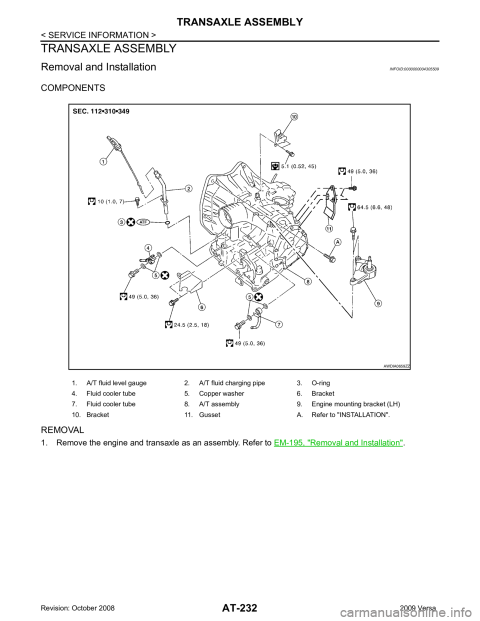
1. A/T fluid level gauge 2. A/T fluid charging pipe 3. O-ring
4. Fluid cooler tube 5. Copper washer 6. Bracket
7. Fluid cooler tube 8. A/T assembly 9. Engine mounting bracket (LH)
10. Bracket 11. Gusset A. Refer to "INSTALLATION".
Page 238 of 4331
AT
N
O P
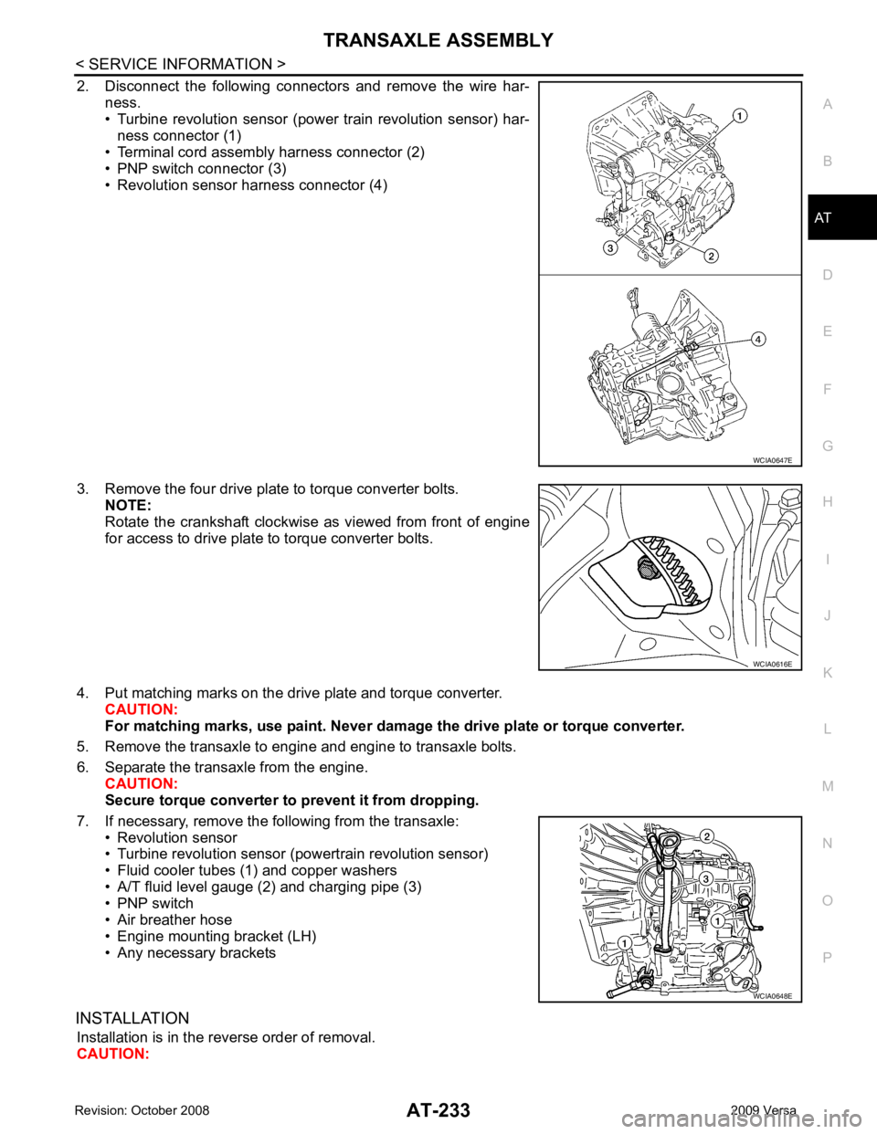
2. Disconnect the following connectors and remove the wire har-
ness.
• Turbine revolution sensor (power train revolution sensor) har-
ness connector (1)
• Terminal cord assembly harness connector (2)
• PNP switch connector (3)
• Revolution sensor harness connector (4)
3. Remove the four drive plate to torque converter bolts. NOTE:
Rotate the crankshaft clockwise as viewed from front of engine
for access to drive plate to torque converter bolts.
4. Put matching marks on the drive plate and torque converter. CAUTION:
For matching marks, use paint. Never dama ge the drive plate or torque converter.
5. Remove the transaxle to engine and engine to transaxle bolts.
6. Separate the transaxle from the engine. CAUTION:
Secure torque converter to prevent it from dropping.
7. If necessary, remove the following from the transaxle: • Revolution sensor
• Turbine revolution sensor (powertrain revolution sensor)
• Fluid cooler tubes (1) and copper washers
• A/T fluid level gauge (2) and charging pipe (3)
• PNP switch
• Air breather hose
• Engine mounting bracket (LH)
• Any necessary brackets
INSTALLATION Installation is in the reverse order of removal.
CAUTION: WCIA0616E
WCIA0648E
Page 380 of 4331

AT
N
O P
Unit: mm (in)
Accumulator INFOID:0000000004305540
RETURN SPRINGS Unit: mm (in)
Unit: mm (in)
O-RINGS Unit: mm (in)
Clutches and Brakes INFOID:0000000004807940
REVERSE CLUTCH Location spring designation Free length (l) Outer diameter (D)
Upper body L14 Pilot valve spring 38.98 (1.5346) 8.9 (0.350)
L15 1–2 accumulator valve spring 20.5 (0.807) 6.95 (0.2736)
1–2 accumulator piston spring 55.66 (2.1913) 19.5 (0.768)
L16 1st reducing valve spring 27.0 (1.063) 7.0 (0.276)
L17 3–2 timing valve spring 23.0 (0.906) 6.65 (0.2618)
L18 Overrun clutch reducing valve spring 37.5 (1.476) 7.0 (0.276)
L19 Torque converter relief valve spring 33.3 (1.311) 9.0 (0.354)
L20 Torque converter clutch control valve spring 53.01 (2.0870) 6.5 (0.256)
L21 Cooler check valve spring 28.04 (1.1039) 7.15 (0.2815)
Lower body L3 Pressure regulator valve sp
ring 45.0 (1.772) 15.0 (0.591)
L4 Overrun clutch control valve spring 21.7 (0.854) 7.0 (0.276)
L5 Accumulator control valve spring 22.0 (0.866) 6.5 (0.256)
L6 Shift valve A spring 21.7 (0.854) 7.0 (0.276)
L7 Shuttle valve spring 51.0 (2.008) 5.65 (0.2224)
L12 Shift valve B spring 21.7 (0.854) 7.0 (0.276)
L13 Pressure modifier valve spring 32.0 (1.260) 6.9 (0.272)
Pressure modifier piston spring 30.5 (1.201) 9.8 (0.386)
— Line pressure relief valve spring 17.02 (0.6701) 8.0 (0.315)
— Torque converter pressure holding spring 9.0 (0.354) 7.3 (0.287) Location Free length (L
1)
Servo release accumulator 62.8 (2.472) Location Length (L
2)
N-D accumulator 46.5 (1.831)Location Inner diameter (Small) Inner diameter (Large)
Servo release accumulator 26.9 (1.059) 44.2 (1.740)
N-D accumulator 34.6 (1.362) 39.4 (1.551) Number of drive plates
2
Number of driven plates 2
Drive plate thickness [mm (in)] Standard 2.0 (0.079)
Allowable limit 1.8 (0.071)
Driven plate thickness [mm (in)] Standard 2.0 (0.079)
Clearance [mm (in)] Standard 0.5 - 0.8 (0.020 - 0.031)
Allowable limit 1.2 (0.047)
Page 911 of 4331
CO
NP
O
Do not remove radiator cap when the engine is
hot. Serious burns could occur from high-pressure
engine coolant escaping from radiator. Wrap a thick cl oth around the cap. Slowly turn it a quarter of a
turn to release built-up pressure. Carefully remove radiator cap by turning it all the way.
REMOVAL 1. Drain engine coolant from radiator. Refer to CO-11, " Changing Engine Coolant " .
CAUTION:
• Perform this step when engine is cold.
• Do not spill engine coolant on drive belt.
2. Remove air duct (inlet). Refer to EM-26, " Exploded View " .
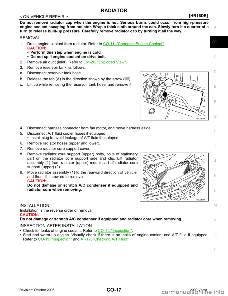
3. Remove reservoir tank as follows:
a. Disconnect reservoir tank hose.
b. Release the tab (A) in the direction shown by the arrow ( ).
c. Lift up while removing the reservoir tank hose, and remove it.
4. Disconnect harness connector from fan motor, and move harness aside.
5. Disconnect A/T fluid cooler hoses if equipped. • Install plug to avoid leakage of A/T fluid if equipped.
6. Remove radiator hoses (upper and lower).
7. Remove radiator core support cover.
8. Remove radiator core support (upper) bolts, bolts of stationary part on the radiator core support side and clip. Lift radiator
assembly (1) from radiator (upper) mount part of radiator core
support (upper) (2).
9. Move radiator assembly (1) to the rearward direction of vehicle, and then lift it upward to remove.
CAUTION:
Do not damage or scratch A/C condenser if equipped and
radiator core when removing.
INSTALLATION Installation is the reverse order of removal.
CAUTION:
Do not damage or scratch A/C condenser if equipped and radiator core when removing.
INSPECTION AFTER INSTALLATION • Check for leaks of engine coolant. Refer to CO-11, " Inspection " .
• Start and warm up engine. Visually check if there is no leaks of engine coolant and A/T fluid if equipped.
Refer to CO-11, " Inspection " and
AT-17, " Checking A/T Fluid " .
Page 933 of 4331
![NISSAN TIIDA 2009 Service Repair Manual RADIATOR
CO-39
< SERVICE INFORMATION >
[MR18DE] C
D E
F
G H
I
J
K L
M A CO
NP
O
Do not remove radiator cap when the engine is
hot. Serious burns could occur from high-pressure
engine c](/manual-img/5/57398/w960_57398-932.png "NISSAN TIIDA 2009 Service Repair Manual RADIATOR
CO-39
< SERVICE INFORMATION >
[MR18DE] C
D E
F
G H
I
J
K L
M A CO
NP
O
Do not remove radiator cap when the engine is
hot. Serious burns could occur from high-pressure
engine c")
RADIATOR
CO-39
< SERVICE INFORMATION >
[MR18DE] C
D E
F
G H
I
J
K L
M A CO
NP
O
Do not remove radiator cap when the engine is
hot. Serious burns could occur from high-pressure
engine coolant escaping from radiator. Wrap a thick cl oth around the cap. Slowly turn it a quarter of a
turn to release built-up pressure. Carefully remove radiator cap by turning it all the way.
REMOVAL 1. Drain engine coolant from radiator. Refer to CO-35, " Changing Engine Coolant " .
CAUTION:
• Perform this step when engine is cold.
• Do not spill engine coolant on drive belt.
2. Remove engine undercover.
3. Remove air duct (inlet). Refer to EM-139 .
4. Remove reservoir tank as follows:
a. Disconnect reservoir tank hose.
b. Release the tab (A) in the direction shown by the arrow ( ).
c. Lift up while removing the reservoir tank hose, and remove it.
5. Disconnect harness connector from fan motor, and move harness aside.
6. Disconnect CVT or A/T fluid cooler hoses if equipped. • Install plug to avoid leakage of CVT or A/T fluid if equipped.
7. Remove radiator hoses (upper and lower).
8. Remove radiator core support cover. Refer to BL-19 .
9. Remove radiator core support (upper) bolts, bolts of stationary part on the radiator core support side and clip. Lift radiator from
radiator (upper) mount part of radiator core support (upper) (2).
10. Move radiator assembly (1) to the rearward direction of vehicle, and then lift it upward to remove.
CAUTION:
Do not damage or scratch A/C condenser if equipped and
radiator core when removing.
INSTALLATION Installation is in the reverse order of removal.
CAUTION:
Do not damage or scratch A/C condenser if eq uipped and radiator core when installing.
INSPECTION AFTER INSTALLATION • Check for leaks of engine coolant. Refer to CO-35, " Inspection " .
• Start and warm up engine. Visually check for leaks of engine coolant and CVT or A/T fluid if equipped. Refer
to CVT-196 or
AT-17 . PBIC3800E
PBIC3805E
Page 939 of 4331
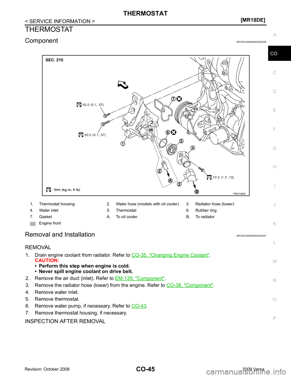
CO
NP
O
THERMOSTAT
Component INFOID:0000000004305246
Removal and Installation INFOID:0000000004305247
REMOVAL 1. Drain engine coolant from radiator. Refer to CO-35, " Changing Engine Coolant " .
CAUTION:
• Perform this step when engine is cold.
• Never spill engine coolant on drive belt.
2. Remove the air duct (inlet). Refer to EM-139, " Component " .
3. Remove the radiator hose (lower) from the engine. Refer to CO-38, " Component " .
4. Remove water inlet.
5. Remove thermostat.
6. Remove water pump, if necessary. Refer to CO-43 .
7. Remove thermostat housing, if necessary.
INSPECTION AFTER REMOVAL 1. Thermostat housing 2. Water hose (models with oil cooler) 3. Radiator hose (lower)
4. Water inlet 5. Thermostat 6. Rubber ring
7. Gasket A. To oil cooler B. To radiator Engine front
Page 945 of 4331

CVT
N
O P
CONTENTS
CVT
RE0F08A
SERVICE INFORMATION .. ..........................
9
INDEX FOR DTC ............................................ .....9
Alphabetical Index ............................................... ......9
DTC No. Index .................................................... ......9
PRECAUTIONS .............................................. ....11
Precaution for Supplemental Restraint System
(SRS) "AIR BAG" and "SEAT BELT PRE-TEN-
SIONER" ............................................................. ....
11
Precaution Necessary fo r Steering Wheel Rota-
tion After Battery Disconnect ............................... ....
11
Precaution for On Board Diagnosis (OBD) System
of CVT and Engine .............................................. ....
12
Service After Replacing TCM and Transaxle As-
sembly ................................................................. ....
12
Removal and Installation Procedure for CVT Unit
Connector ............................................................ ....
13
Precaution ........................................................... ....14
Service Notice or Precaution ............................... ....15
PREPARATION .............................................. ....16
Special Service Tool ........................................... ....16
Commercial Service Tool .................................... ....16
CVT FLUID ..................................................... ....17
Checking CVT Fluid ............................................ ....17
Changing CVT Fluid ............................................ ....18
CVT Fluid Cooler Cleanin g .....................................18
CVT SYSTEM ... .............................................. ....22
Cross-Sectional View - RE0F08A ....................... ....22
Control System .................................................... ....23
Hydraulic Control System ........................................24
TCM Function ...................................................... ....24
CAN Communication ........................................... ....25
Input/Output Signal of TCM ................................. ....26
Line Pressure and Secondary Pressure Control . ....26
Shift Control ........................................................ ....27
Lock-up and Select Control ................................. ....28 Control Valve .......................................................
....29
ON BOARD DIAGNOSTIC (OBD) SYSTEM .... 30
Introduction .......................................................... ....30
OBD-II Function for CVT System ........................ ....30
One or Two Trip Detection Logic of OBD-II ......... ....30
OBD-II Diagnostic Trouble Code (DTC) .............. ....30
Malfunction Indicator Lamp (MIL) ............................31
TROUBLE DIAGNOSIS .................................... 33
DTC Inspection Priority Chart .............................. ....33
Fail-Safe .............................................................. ....33
How to Perform Trouble Diagnosis for Quick and
Accurate Repair ................................................... ....
34
CVT Electrical Parts Location .............................. ....39
Circuit Diagram .................................................... ....40
Inspections before Trouble Diagnosis ................. ....40
Road Test ............................................................ ....44
Check before Engine Is Started ........................... ....45
Check at Idle ........................................................ ....45
Cruise Test .......................................................... ....47
Vehicle Speed When Shifting Gears ................... ....49
TCM Terminal and Refere nce Value .......................49
CONSULT-III Function (TRANSMISSION) .......... ....51
Diagnosis Procedure withou t CONSULT-III ............59
DTC U1000 CAN COMMUNICATION LINE ..... 60
Description ........................................................... ....60
On Board Diagnosis Logic ................................... ....60
Possible Cause .................................................... ....60
DTC Confirmation Procedure .............................. ....60
Wiring Diagram - CVT - CAN ............................... ....61
Diagnosis Procedure ........................................... ....62
DTC U1010 TRANSMISSION CONTROL
MODULE (CAN) ................................................ 63
Description ........................................................... ....63
On Board Diagnosis Logic ................................... ....63
Possible Cause .................................................... ....63
DTC Confirmation Procedure .............................. ....63
Diagnosis Procedure ........................................... ....63