2009 NISSAN TIIDA engine control unit
[x] Cancel search: engine control unitPage 1089 of 4331
CVT
N
O P
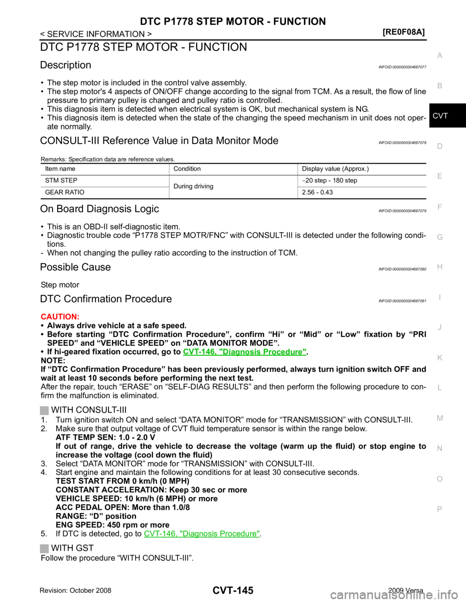
DTC P1778 STEP MOTOR - FUNCTION
Description INFOID:0000000004667077
• The step motor is included in the control valve assembly.
• The step motor's 4 aspects of ON/OFF change according to the signal from TCM. As a result, the flow of line
pressure to primary pulley is changed and pulley ratio is controlled.
• This diagnosis item is detected when electrical system is OK, but mechanical system is NG.
• This diagnosis item is detected when the state of the changing the speed mechanism in unit does not oper-
ate normally.
CONSULT-III Reference Val ue in Data Monitor Mode INFOID:0000000004667078
Remarks: Specification data are reference values.
On Board Diagnosis Logic INFOID:0000000004667079
• This is an OBD-II self-diagnostic item.
• Diagnostic trouble code “P1778 STEP MOTR/FNC” with CO NSULT-III is detected under the following condi-
tions.
- When not changing the pulley ratio according to the instruction of TCM.
Possible Cause INFOID:0000000004667080
Step motor
DTC Confirmation Procedure INFOID:0000000004667081
CAUTION:
• Always drive vehicle at a safe speed.
• Before starting “DTC Confirmation Procedure”, confirm “Hi” or “Mid” or “Low” fixation by “PRI SPEED” and “VEHICLE SPEED” on “DATA MONITOR MODE”.
• If hi-geared fixation occurred, go to CVT-146, " Diagnosis Procedure " .
NOTE:
If “DTC Confirmation Procedure” has been previously performed, alw ays turn ignition switch OFF and
wait at least 10 seconds before performing the next test.
After the repair, touch “ERASE” on “SELF-DIAG RESU LTS” and then perform the following procedure to con-
firm the malfunction is eliminated.
WITH CONSULT-III
1. Turn ignition switch ON and select “DATA MO NITOR” mode for “TRANSMISSION” with CONSULT-III.
2. Make sure that output voltage of CVT fluid temperature sensor is within the range below.
ATF TEMP SEN: 1.0 - 2.0 V
If out of range, drive the vehicle to decrease the voltage (warm up the fluid) or stop engine to
increase the voltage (c ool down the fluid)
3. Select “DATA MONITOR” mode for “TRANSMISSION” with CONSULT-III.
4. Start engine and maintain the following conditions for at least 30 consecutive seconds.
TEST START FROM 0 km/h (0 MPH)
CONSTANT ACCELERATION: Keep 30 sec or more
VEHICLE SPEED: 10 km/h (6 MPH) or more
ACC PEDAL OPEN: More than 1.0/8
RANGE: “D” position
ENG SPEED: 450 rpm or more
5. If DTC is detected, go to CVT-146, " Diagnosis Procedure " .
WITH GST
Follow the procedure “WITH CONSULT-III”. Item name Condition Display value (Approx.)
STM STEP During driving−
20 step - 180 step
GEAR RATIO 2.56 - 0.43
Page 1131 of 4331
CVT
N
O P
SERVICE INFORMATION
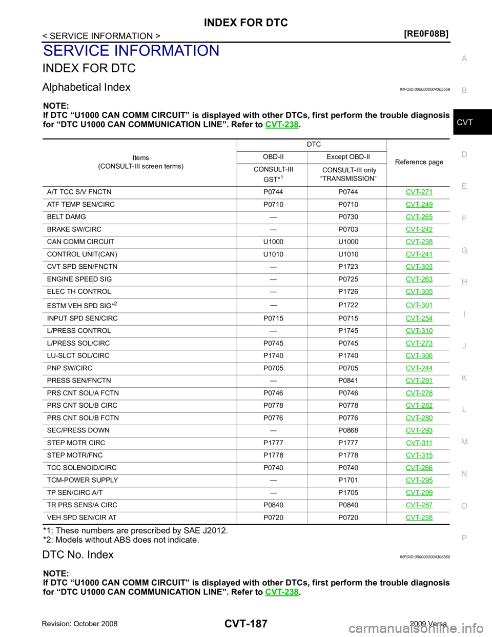
INDEX FOR DTC
Alphabetical Index INFOID:0000000004305559
NOTE:
If DTC “U1000 CAN COMM CIRCUIT” is displayed with other DTCs, first perform the trouble diagnosis
for “DTC U1000 CAN COMMUNICATION LINE”. Refer to CVT-238 .
*1: These numbers are prescribed by SAE J2012.
*2: Models without ABS does not indicate.
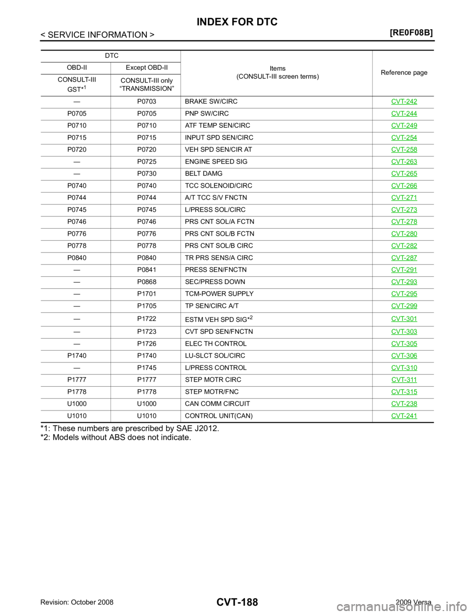
DTC No. Index INFOID:0000000004305560
NOTE:
If DTC “U1000 CAN COMM CIRCUIT” is displayed with other DTCs, first perform the trouble diagnosis
for “DTC U1000 CAN COMMUNICATION LINE”. Refer to CVT-238 .
Items
(CONSULT-III screen terms) DTC
Reference page
OBD-II Except OBD-II
CONSULT-III GST* 1 CONSULT-III only
“TRANSMISSION”
A/T TCC S/V FNCTN P0744 P0744 CVT-271ATF TEMP SEN/CIRC P0710 P0710
CVT-249BELT DAMG — P0730
CVT-265BRAKE SW/CIRC — P0703
CVT-242CAN COMM CIRCU
IT U1000 U1000 CVT-238CONTROL UNIT(CAN) U1010 U1010
CVT-241CVT SPD SEN/FNCTN — P1723
CVT-303ENGINE SPEED SIG — P0725
CVT-263ELEC TH CONTROL — P1726
CVT-305ESTM VEH SPD SIG*
2
— P1722CVT-301INPUT SPD SEN/CIRC P0715 P0715
CVT-254L/PRESS CONTROL — P1745
CVT-310L/PRESS SOL/CIRC P0745 P0745
CVT-273LU-SLCT SOL/CIRC P1740 P1740
CVT-306PNP SW/CIRC P0705 P0705
CVT-244PRESS SEN/FNCTN — P0841
CVT-291PRS CNT SOL/A FCTN P0746 P0746
CVT-278PRS CNT SOL/B CIRC P0778 P0778
CVT-282PRS CNT SOL/B FCTN P0776 P0776
CVT-280SEC/PRESS DOWN — P0868
CVT-293STEP MOTR CIRC P1777 P1777
CVT-311STEP MOTR/FNC P1778 P1778
CVT-315TCC SOLENOID/CIRC P0740 P0740
CVT-266TCM-POWER SUPPLY — P1701
CVT-295TP SEN/CIRC A/T — P1705
CVT-299TR PRS SENS/A CIRC P0840 P0840
CVT-287VEH SPD SEN/CIR AT P0720 P0720
CVT-258
Page 1132 of 4331
P0705 P0705 PNP SW/CIRC
CVT-244P0710 P0710 ATF TEMP SEN/CIRC
CVT-249P0715 P0715 INPUT SPD SEN/CIRC
CVT-254P0720 P0720 VEH SPD SEN/CIR AT
CVT-258— P0725 ENGINE SPEED SIG
CVT-263— P0730 BELT DAMG
CVT-265P0740 P0740 TCC SOLENOID/CIRC
CVT-266P0744 P0744 A/T TCC S/V FNCTN
CVT-271P0745 P0745 L/PRESS SOL/CIRC
CVT-273P0746 P0746 PRS CNT SOL/A FCTN
CVT-278P0776 P0776 PRS CNT SOL/B FCTN
CVT-280P0778 P0778 PRS CNT SOL/B CIRC
CVT-282P0840 P0840 TR PRS SENS/A CIRC
CVT-287— P0841 PRESS SEN/FNCTN
CVT-291— P0868 SEC/PRESS DOWN
CVT-293— P1701 TCM-POWER SUPPLY
CVT-295— P1705 TP SEN/CIRC A/T
CVT-299— P1722
ESTM VEH SPD SIG*2
CVT-301— P1723 CVT SPD SEN/FNCTN
CVT-303— P1726 ELEC TH CONTROL
CVT-305P1740 P1740 LU-SLCT SOL/CIRC
CVT-306— P1745 L/PRESS CONTROL
CVT-310P1777 P1777 STEP MOTR CIRC
CVT-311P1778 P1778 STEP MOTR/FNC
CVT-315U1000 U1000 CAN COMM CIRCUIT
CVT-238U1010 U1010 CONTROL UNIT(CAN)
CVT-241
Page 1133 of 4331
CVT
N
O P
PRECAUTIONS
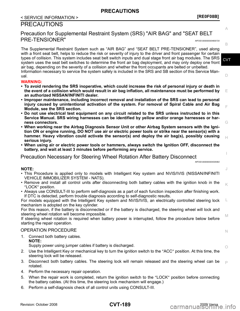
Precaution for Supplemental Restraint System (SRS) "AIR BAG" and "SEAT BELT
PRE-TENSIONER" INFOID:0000000004800720
The Supplemental Restraint System such as “A IR BAG” and “SEAT BELT PRE-TENSIONER”, used along
with a front seat belt, helps to reduce the risk or severi ty of injury to the driver and front passenger for certain
types of collision. This system includes seat belt switch inputs and dual stage front air bag modules. The SRS
system uses the seat belt switches to determine the front air bag deployment, and may only deploy one front
air bag, depending on the severity of a collision and w hether the front occupants are belted or unbelted.
Information necessary to service the system safely is included in the SRS and SB section of this Service Man-
ual.
WARNING:
• To avoid rendering the SRS inoper ative, which could increase the risk of personal injury or death in
the event of a collision which would result in air bag inflation, all maintenance must be performed by
an authorized NISSAN/INFINITI dealer.
• Improper maintenance, including in correct removal and installation of the SRS can lead to personal
injury caused by unintentional act ivation of the system. For removal of Spiral Cable and Air Bag
Module, see the SRS section.
• Do not use electrical test equipm ent on any circuit related to the SRS unless instructed to in this
Service Manual. SRS wiring harnesses can be identi fied by yellow and/or orange harnesses or har-
ness connectors.
• When working near the Airbag Diagnosis Sensor Un it or other Airbag System sensors with the Igni-
tion ON or engine running, DO NOT use air or el ectric power tools or strike near the sensor(s) with a
hammer. Heavy vibration could activate the sensor( s) and deploy the air bag(s), possibly causing
serious injury.
• When using air or electric power tools or hammers , always switch the Ignition OFF, disconnect the
battery, and wait at least 3 minutes before performing any service.
Precaution Necessary for Steering Wh eel Rotation After Battery Disconnect
INFOID:0000000004305562
NOTE:
• This Procedure is applied only to models with Intell igent Key system and NVIS/IVIS (NISSAN/INFINITI
VEHICLE IMMOBILIZER SYSTEM - NATS).
• Remove and install all control units after disconnecti ng both battery cables with the ignition knob in the
″ LOCK ″ position.
• Always use CONSULT-III to perform self-diagnosis as a part of each function inspection after finishing work.
If DTC is detected, perform trouble diagnosis according to self-diagnostic results.
For models equipped with the Intelligent Key system and NVIS/IVIS, an electrically controlled steering lock
mechanism is adopted on the key cylinder.
For this reason, if the battery is disconnected or if the battery is discharged, the steering wheel will lock and
steering wheel rotation will become impossible.
If steering wheel rotation is required when battery pow er is interrupted, follow the procedure below before
starting the repair operation.
OPERATION PROCEDURE 1. Connect both battery cables. NOTE:
Supply power using jumper cables if battery is discharged.
2. Use the Intelligent Key or mechanical key to turn the ignition switch to the ″ACC ″ position. At this time, the
steering lock will be released.
3. Disconnect both battery cables. The steering lock will remain released and the steering wheel can be
rotated.
4. Perform the necessary repair operation.
5. When the repair work is completed, return the ignition switch to the ″LOCK ″ position before connecting
the battery cables. (At this time, the steering lock mechanism will engage.)
6. Perform a self-diagnosis check of al l control units using CONSULT-III.
Page 1177 of 4331
CVT
N
O P
CAUTION:
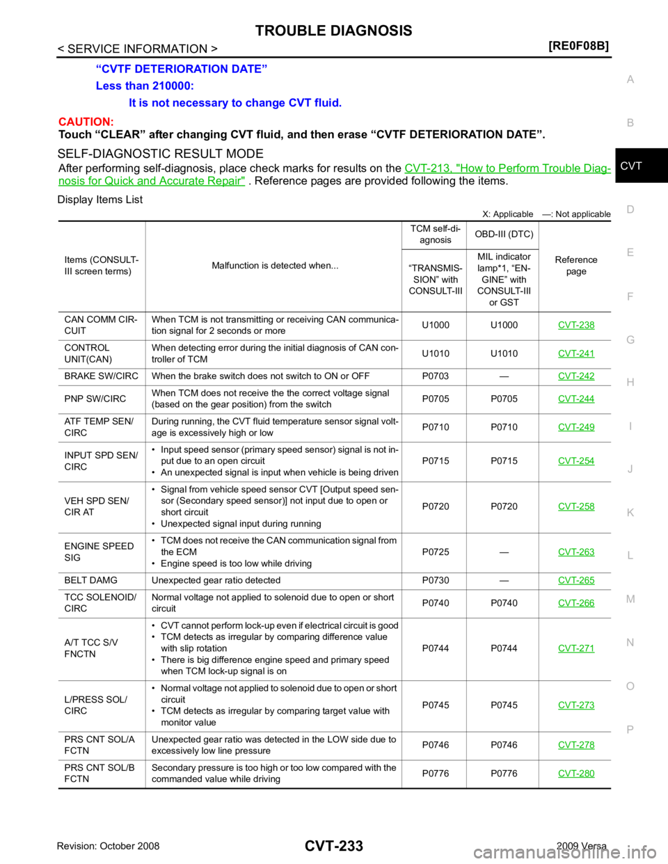
Touch “CLEAR” after changing CVT fluid, and then erase “CVTF DETERIORATION DATE”.
SELF-DIAGNOSTIC RESULT MODE After performing self-diagnosis, place check marks for results on the CVT-213, " How to Perform Trouble Diag-
nosis for Quick and Accurate Repair " . Reference pages are provided following the items.
Display Items List X: Applicable —: Not applicable
Less than 210000:
It is not necessary to change CVT fluid.
“CVTF DETERIORATION DATE”
Items (CONSULT-
III screen terms) Malfunction is detected when... TCM self-di-
agnosis OBD-III (DTC)
Reference page
“TRANSMIS-
SION” with
CONSULT-III MIL indicator
lamp*1, “EN- GINE” with
CONSULT-III
or GST
CAN COMM CIR-
CUIT When TCM is not transmitting or receiving CAN communica-
tion signal for 2 seconds or more U1000 U1000
CVT-238CONTROL
UNIT(CAN) When detecting error during the initial diagnosis of CAN con-
troller of TCM U1010 U1010
CVT-241BRAKE SW/CIRC When the brake switch does not switch to ON or OFF P0703 —
CVT-242PNP SW/CIRC
When TCM does not receive the the correct voltage signal
(based on the gear position) from the switch P0705 P0705
CVT-244ATF TEMP SEN/
CIRC During running, the CVT fluid temperature sensor signal volt-
age is excessively high or low P0710 P0710
CVT-249INPUT SPD SEN/
CIRC • Input speed sensor (primary speed sensor) signal is not in-
put due to an open circuit
• An unexpected signal is input when vehicle is being driven P0715 P0715
CVT-254VEH SPD SEN/
CIR AT • Signal from vehicle speed sensor CVT [Output speed sen-
sor (Secondary speed sensor)] not input due to open or
short circuit
• Unexpected signal input during running P0720 P0720
CVT-258ENGINE SPEED
SIG • TCM does not receive the CAN communication signal from
the ECM
• Engine speed is too low while driving P0725 —
CVT-263BELT DAMG Unexpected gear ratio detected P0730 —
CVT-265TCC SOLENOID/
CIRC Normal voltage not applied to solenoid due to open or short
circuit P0740 P0740
CVT-266A/T TCC S/V
FNCTN • CVT cannot perform lock-up even if electrical circuit is good
• TCM detects as irregular by comparing difference value with slip rotation
• There is big difference engine speed and primary speed
when TCM lock-up signal is on P0744 P0744
CVT-271L/PRESS SOL/
CIRC • Normal voltage not applied to solenoid due to open or short
circuit
• TCM detects as irregular by comparing target value with
monitor value P0745 P0745
CVT-273PRS CNT SOL/A
FCTN Unexpected gear ratio was detected in the LOW side due to
excessively low line pressure P0746 P0746
CVT-278PRS CNT SOL/B
FCTN Secondary pressure is too high or too low compared with the
commanded value while driving P0776 P0776
CVT-280
Page 1178 of 4331
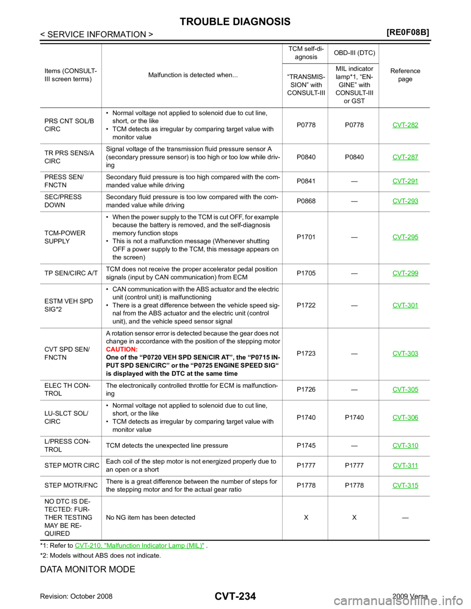
Malfunction Indicator Lamp (MIL) " .
*2: Models without ABS does not indicate.
DATA MONITOR MODE PRS CNT SOL/B
CIRC • Normal voltage not applied to solenoid due to cut line,
short, or the like
• TCM detects as irregular by comparing target value with
monitor value P0778 P0778
CVT-282TR PRS SENS/A
CIRC Signal voltage of the transmission fluid pressure sensor A
(secondary pressure sensor) is too high or too low while driv-
ing P0840 P0840
CVT-287PRESS SEN/
FNCTN Secondary fluid pressure is too high compared with the com-
manded value while driving P0841 —
CVT-291SEC/PRESS
DOWN Secondary fluid pressure is too low compared with the com-
manded value while driving P0868 —
CVT-293TCM-POWER
SUPPLY • When the power supply to the TCM is cut OFF, for example
because the battery is removed, and the self-diagnosis
memory function stops
• This is not a malfunction message (Whenever shutting OFF a power supply to the TCM, this message appears on
the screen) P1701 —
CVT-295TP SEN/CIRC A/T
TCM does not receive the proper accelerator pedal position
signals (input by CAN communication) from ECM P1705 —
CVT-299ESTM VEH SPD
SIG*2 • CAN communication with the
ABS actuator and the electric
unit (control unit) is malfunctioning
• There is a great difference between the vehicle speed sig- nal from the ABS actuator and the electric unit (control
unit), and the vehicle speed sensor signal P1722 —
CVT-301CVT SPD SEN/
FNCTN A rotation sensor error is detected because the gear does not
change in accordance with the position of the stepping motor
CAUTION:
One of the “P0720 VEH SPD SEN/CIR AT”, the “P0715 IN-
PUT SPD SEN/CIRC” or the “P0725 ENGINE SPEED SIG“
is displayed with the DTC at the same time P1723 —
CVT-303ELEC TH CON-
TROL The electronically controlled throttle for ECM is malfunction-
ing P1726 —
CVT-305LU-SLCT SOL/
CIRC • Normal voltage not applied to solenoid due to cut line,
short, or the like
• TCM detects as irregular by comparing target value with monitor value P1740 P1740
CVT-306L/PRESS CON-
TROL TCM detects the unexpected line pressure P1745 —
CVT-310STEP MOTR CIRC
Each coil of the step motor is not energized properly due to
an open or a short P1777 P1777
CVT-311STEP MOTR/FNC
There is a great difference between the number of steps for
the stepping motor and for the actual gear ratio P1778 P1778
CVT-315NO DTC IS DE-
TECTED: FUR-
THER TESTING
MAY BE RE-
QUIRED No NG item has been detected X X —
Items (CONSULT-
III screen terms) Malfunction is detected when... TCM self-di-
agnosis OBD-III (DTC)
Reference page
“TRANSMIS-
SION” with
CONSULT-III MIL indicator
lamp*1, “EN- GINE” with
CONSULT-III
or GST
Page 1185 of 4331
CVT
N
O P
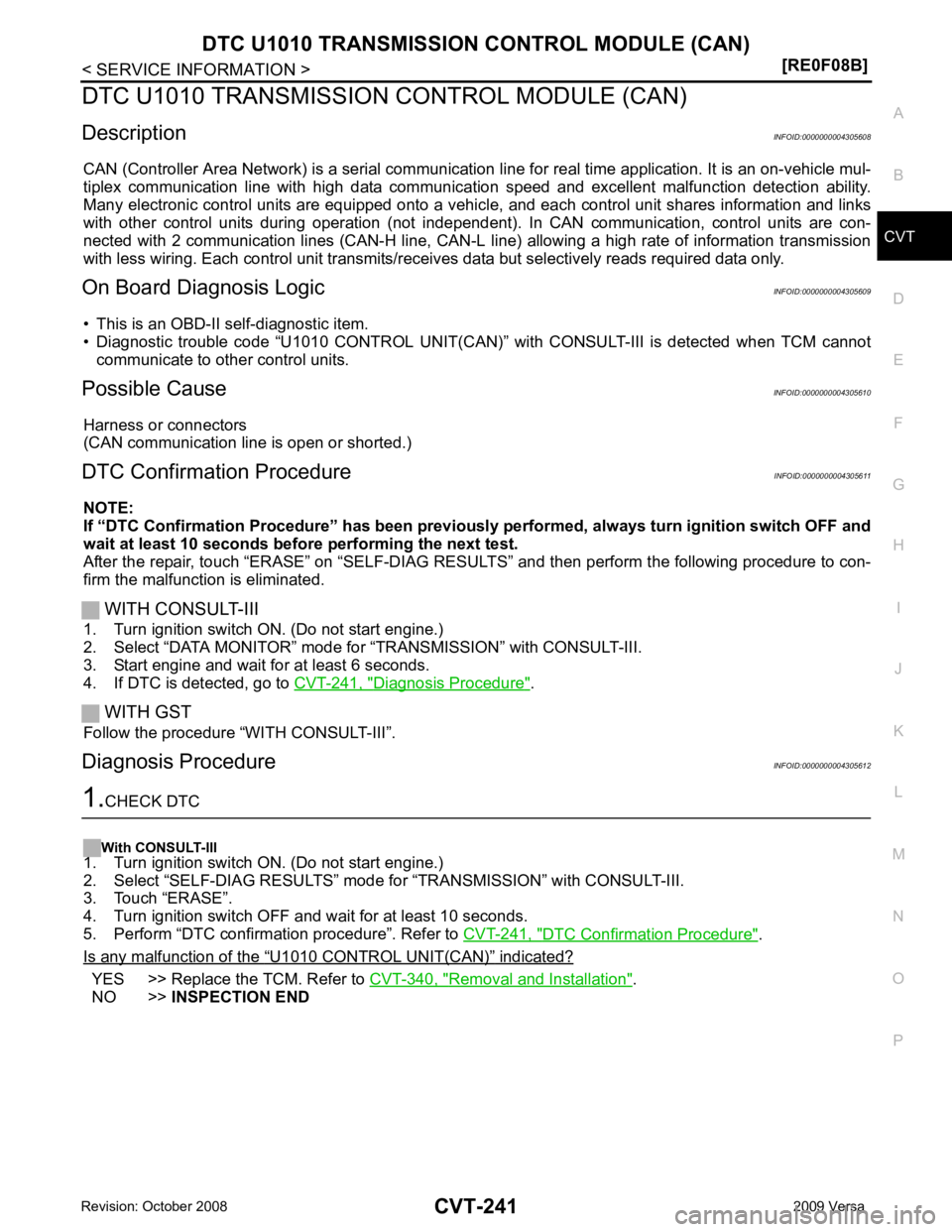
DTC U1010 TRANSMISSION
CONTROL MODULE (CAN)
Description INFOID:0000000004305608
CAN (Controller Area Network) is a serial communication li ne for real time application. It is an on-vehicle mul-
tiplex communication line with high data communica tion speed and excellent malfunction detection ability.
Many electronic control units are equipped onto a vehicl e, and each control unit shares information and links
with other control units during operation (not independent ). In CAN communication, control units are con-
nected with 2 communication lines (CAN-H line, CAN-L li ne) allowing a high rate of information transmission
with less wiring. Each control unit transmits/recei ves data but selectively reads required data only.
On Board Diagnosis Logic INFOID:0000000004305609
• This is an OBD-II self-diagnostic item.
• Diagnostic trouble code “U1010 CONTROL UNIT(CAN)” with CONSULT-III is detected when TCM cannot
communicate to other control units.
Possible Cause INFOID:0000000004305610
Harness or connectors
(CAN communication line is open or shorted.)
DTC Confirmation Procedure INFOID:0000000004305611
NOTE:
If “DTC Confirmation Procedure” has been previously performed, alw ays turn ignition switch OFF and
wait at least 10 seconds before performing the next test.
After the repair, touch “ERASE” on “SELF-DIAG RESU LTS” and then perform the following procedure to con-
firm the malfunction is eliminated.
WITH CONSULT-III
1. Turn ignition switch ON. (Do not start engine.)
2. Select “DATA MONITOR” mode for “TRANSMISSION” with CONSULT-III.
3. Start engine and wait for at least 6 seconds.
4. If DTC is detected, go to CVT-241, " Diagnosis Procedure " .
WITH GST
Follow the procedure “WITH CONSULT-III”.
Diagnosis Procedure INFOID:0000000004305612DTC Confirmation Procedure " .
Is any malfunction of the “ U1010 CONTROL UNIT(CAN) ” indicated?
YES >> Replace the TCM. Refer to
CVT-340, " Removal and Installation " .
NO >> INSPECTION END
Page 1219 of 4331
![NISSAN TIIDA 2009 Service Repair Manual DTC P0745 LINE PRESSURE SOLENOID VALVE
CVT-275
< SERVICE INFORMATION >
[RE0F08B] D
E
F
G H
I
J
K L
M A
B CVT
N
O P
Diagnosis Procedure
INFOID:00000000043056881.
CHECK INPUT SIGNAL
With CONSULT-III
1. NISSAN TIIDA 2009 Service Repair Manual DTC P0745 LINE PRESSURE SOLENOID VALVE
CVT-275
< SERVICE INFORMATION >
[RE0F08B] D
E
F
G H
I
J
K L
M A
B CVT
N
O P
Diagnosis Procedure
INFOID:00000000043056881.
CHECK INPUT SIGNAL
With CONSULT-III
1.](/manual-img/5/57398/w960_57398-1218.png)
DTC P0745 LINE PRESSURE SOLENOID VALVE
CVT-275
< SERVICE INFORMATION >
[RE0F08B] D
E
F
G H
I
J
K L
M A
B CVT
N
O P
Diagnosis Procedure
INFOID:00000000043056881.
CHECK INPUT SIGNAL
With CONSULT-III
1. Start engine.
2. Select “MAIN SIGNALS” in “DATA MONITOR” mode for “TRANSMISSION” with CONSULT-III.
3. Read out the value of “ISOLT2”.
Without CONSULT-III
1. Start engine.
2. Check voltage between TCM connector terminal and ground.
3. Turn ignition switch OFF.
4. Disconnect TCM connector.
5. Check if there is continuity between connector terminal and ground.
OK or NG OK >> GO TO 5.
NG >> GO TO 2. 2.
CHECK PRESSURE CONTROL SOLENOID VALVE A (LINE PRESSURE SOLENOID VALVE) CIRCUIT
1. Turn ignition switch OFF.
2. Disconnect TCM connector.
3. Check resistance between TCM connector terminal and ground.
OK or NG OK >> GO TO 5.
NG >> GO TO 3. 3.
CHECK VALVE RESISTANCE
1. Turn ignition switch OFF.
2. Disconnect CVT unit harness connector. Item name Condition Display value (Approx.)
ISOLT2 Release your foot from the
accelerato r pedal. 0.8 A
Press the accelerator ped-
al all the way down. 0.0 AName Connector Terminal Condition
Voltage
(Approx.)
Pressure
control so-
lenoid
valve A
(Line pres-
sure sole-
noid valve) E31 1 - ground Release your foot from
the accelerator pedal. 5.0 - 7.0 V
Press the accelerator
pedal all the way down. 1.0 - 3.0 V SCIA2348E
Solenoid valve Connector Terminal
Resistance (Ap-
prox.)
Pressure control solenoid valve A
(Line pressure solenoid valve) E31 1 - ground 3 - 9
Ω SCIA4685E