2009 NISSAN TIIDA break
[x] Cancel search: breakPage 3216 of 4331

FRONT DRIVE SHAFT
FAX-21
< SERVICE INFORMATION >
C
E F
G H
I
J
K L
M A
B FAX
N
O P
1. Install new boot and new small boot band on shaft.
CAUTION:
• Do not reuse boot or boot band.
• Cover drive shaft serration with tape to prevent damage to
boot during installation.
2. Remove protective tape wound around serrated part of shaft.
3. Align matching mark on spider assembly with matching mark on shaft and install spider assembly with chamfer facing shaft.
4. Install new snap ring using a suitable tool. CAUTION:
Do not reuse snap ring.
5. Apply recommended grease (Genuine NISSAN Grease or equivalent) to spider assembly and sliding surface.
6. Install the slide joint housing onto the spider assembly and pack with the balance of recommended grease (Genuine NISSAN
Grease or equivalent).
7. Install boot securely into grooves (indicated by * marks) as shown.
CAUTION:
If there is grease on boot mounting surfaces (indicated by *
marks) of shaft and housing, boot may come off. Clean all
grease from surfaces.
8. Make sure boot installation length (L) is the length specified below. Insert a flat-bladed screwdriver or similar tool into the
large end of boot. Bleed air from boot to prevent boot deforma-
tion.
CAUTION:
• Boot may break if boot installation le ngth is outside the standard value.
• Be careful that screwdriver tip does not contact inside surface of boot.
9. Secure large end of boot with new boot band. 1. Set boot band onto boot and insert first pawl on boot band into the first groove on opposite end of boot band. SFA800
SDIA2629E
Grease amount : 130 – 140 g (4.6 – 4.9 oz)
SFA023A
Boot installation length (L)
A/T models : 178 mm (7.01 in)
Except for A/T models : 168 mm (6.61 in) SDIA3285E
Page 3218 of 4331

FRONT DRIVE SHAFT
FAX-23
< SERVICE INFORMATION >
C
E F
G H
I
J
K L
M A
B FAX
N
O P
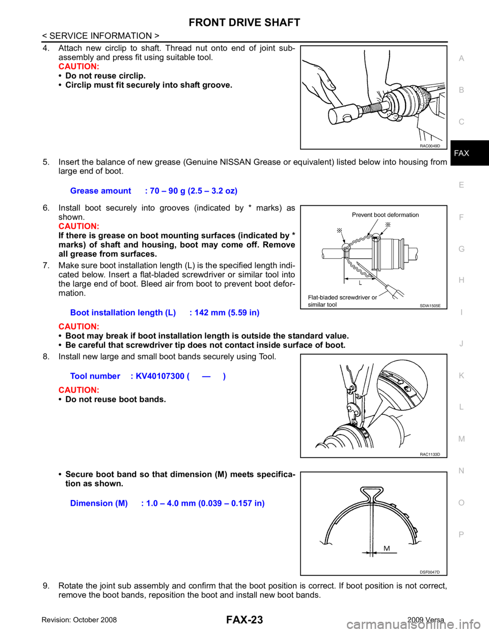
4. Attach new circlip to shaft. Thread nut onto end of joint sub-
assembly and press fit using suitable tool.
CAUTION:
• Do not reuse circlip.
• Circlip must fit securely into shaft groove.
5. Insert the balance of new grease (Genuine NISSAN Grease or equivalent) listed below into housing from
large end of boot.
6. Install boot securely into grooves (indicated by * marks) as shown.
CAUTION:
If there is grease on boot mounting surfaces (indicated by *
marks) of shaft and housing, boot may come off. Remove
all grease from surfaces.
7. Make sure boot installation length (L) is the specified length indi- cated below. Insert a flat-bladed screwdriver or similar tool into
the large end of boot. Bleed air from boot to prevent boot defor-
mation.
CAUTION:
• Boot may break if boot installation le ngth is outside the standard value.
• Be careful that screwdriver tip does not contact inside surface of boot.
8. Install new large and small boot bands securely using Tool.
CAUTION:
• Do not reuse boot bands.
• Secure boot band so that dimension (M) meets specifica- tion as shown.
9. Rotate the joint sub assembly and confirm that the boot position is correct. If boot position is not correct,
remove the boot bands, reposition the boot and install new boot bands. RAC0049D
Grease amount : 70 – 90 g (2.5 – 3.2 oz)
Boot installation length (L) : 142 mm (5.59 in)
Tool number : KV40107300 ( — ) SDIA1505E
RAC1133D
Dimension (M) : 1.0 – 4.0 mm (0.039 – 0.157 in)
DSF0047D
Page 3724 of 4331
![NISSAN TIIDA 2009 Service Repair Manual PRECAUTIONS
LU-3
< PRECAUTION >
[HR16DE] C
D E
F
G H
I
J
K L
M A LU
NP
O
Precaution for Liquid Gasket
INFOID:0000000004784386
REMOVAL OF LIQUID GASKET SEALING • After removing nuts and bolts, separa NISSAN TIIDA 2009 Service Repair Manual PRECAUTIONS
LU-3
< PRECAUTION >
[HR16DE] C
D E
F
G H
I
J
K L
M A LU
NP
O
Precaution for Liquid Gasket
INFOID:0000000004784386
REMOVAL OF LIQUID GASKET SEALING • After removing nuts and bolts, separa](/manual-img/5/57398/w960_57398-3723.png)
PRECAUTIONS
LU-3
< PRECAUTION >
[HR16DE] C
D E
F
G H
I
J
K L
M A LU
NP
O
Precaution for Liquid Gasket
INFOID:0000000004784386
REMOVAL OF LIQUID GASKET SEALING • After removing nuts and bolts, separate the mating surface, using Tool and remove old liquid gasket sealing.
CAUTION:
Be careful not to damage the mating surfaces.
• Tap Tool to insert it (1), and then slide it by tapping on the side (2) as shown.
• In areas where Tool is difficult to use, use plastic hammer to lightly tap the parts, to remove it.
CAUTION:
If for some unavoidable reason suitable tool such as screw-
driver is used, be careful not to damage the mating surfaces.
LIQUID GASKET APPLICATION PROCEDURE 1. Remove old liquid gasket adhering to the liquid gasket applica- tion surface and the mating surface, using scraper.
• Remove liquid gasket completely from the groove of the liquid
gasket application surface, bolts, and bolt holes.
2. Thoroughly clean the mating surfaces and remove adhering moisture, grease and foreign materials.
3. Attach liquid gasket tube to Tool.
Use Genuine RTV Silicone Seal ant or equivalent. Refer to GI-42, " Recommended Chemical Prod-
uct and Sealant " .
4. Apply liquid gasket without breaks to the spec ified location with the specified dimensions.
• If there is a groove for the liquid gasket application, apply liquid gasket to the groove.
• As for the bolt holes, normally apply liquid gasket inside the holes. Occasionally, it should be applied outside the holes.
Make sure to read the text of service manual.
• Within five minutes of liquid gasket application, install the mat- ing component.
• If liquid gasket protrudes, wipe it off immediately.
• Do not retighten nuts or bolts after the installation.
• After 30 minutes or more have passed from the installation, fill engine oil and engine coolant.
CAUTION:
If there are specific instructions in this manual, observe them.
Tool number : KV10111100 (J-37228)
WBIA0566E
Tool number : WS39930000 ( — )
PBIC0003E
WBIA0567E
SEM159F
Page 3733 of 4331
![NISSAN TIIDA 2009 Service Repair Manual LU-12< SERVICE INFORMATION >
[MR18DE]
PRECAUTIONS
Precaution for Liquid Gasket INFOID:0000000004788557
REMOVAL OF LIQUID GASKET SEALING
• After removing nuts and bolts, separate the mating surface, NISSAN TIIDA 2009 Service Repair Manual LU-12< SERVICE INFORMATION >
[MR18DE]
PRECAUTIONS
Precaution for Liquid Gasket INFOID:0000000004788557
REMOVAL OF LIQUID GASKET SEALING
• After removing nuts and bolts, separate the mating surface,](/manual-img/5/57398/w960_57398-3732.png)
LU-12< SERVICE INFORMATION >
[MR18DE]
PRECAUTIONS
Precaution for Liquid Gasket INFOID:0000000004788557
REMOVAL OF LIQUID GASKET SEALING
• After removing nuts and bolts, separate the mating surface, using Tool and remove old liquid gasket sealing.
CAUTION:
Be careful not to damage the mating surfaces.
• Tap Tool to insert it (1), and then slide it by tapping on the side (2) as shown.
• In areas where Tool is difficult to use, use plastic hammer to lightly tap the parts, to remove it.
CAUTION:
If for some unavoidable reason suitable tool such as screw-
driver is used, be careful no t to damage the mating surfaces.
LIQUID GASKET APPLICATION PROCEDURE
1. Remove old liquid gasket adhering to the liquid gasket applica- tion surface and the mating surface, using scraper.
• Remove liquid gasket completely from the groove of the liquid
gasket application surface, bolts, and bolt holes.
2. Thoroughly clean the mating surfaces and remove adhering moisture, grease and foreign materials.
3. Attach liquid gasket tube to Tool.
Use Genuine RTV Silicone Seal ant or equivalent. Refer to GI-42, " Recommended Chemical Prod-
uct and Sealant " .
4. Apply liquid gasket without breaks to the specif ied location with the specified dimensions.
• If there is a groove for the liquid gasket application, apply liquid gasket to the groove.
• As for the bolt holes, normally apply liquid gasket inside the holes. Occasionally, it should be applied outside the holes.
Make sure to read the text of service manual.
• Within five minutes of liquid gasket application, install the mat- ing component.
• If liquid gasket protrudes, wipe it off immediately.
• Do not retighten nuts or bolts after the installation.
• After 30 minutes or more have passed from the installation, fill engine oil and engine coolant.
CAUTION:
If there are specific instructions in this manual, observe them.
Tool number : KV10111100 (J-37228)
WBIA0566E
Tool number : WS39930000 ( — )
PBIC0003E
WBIA0567E
SEM159F
Page 3833 of 4331

MT
N
O P
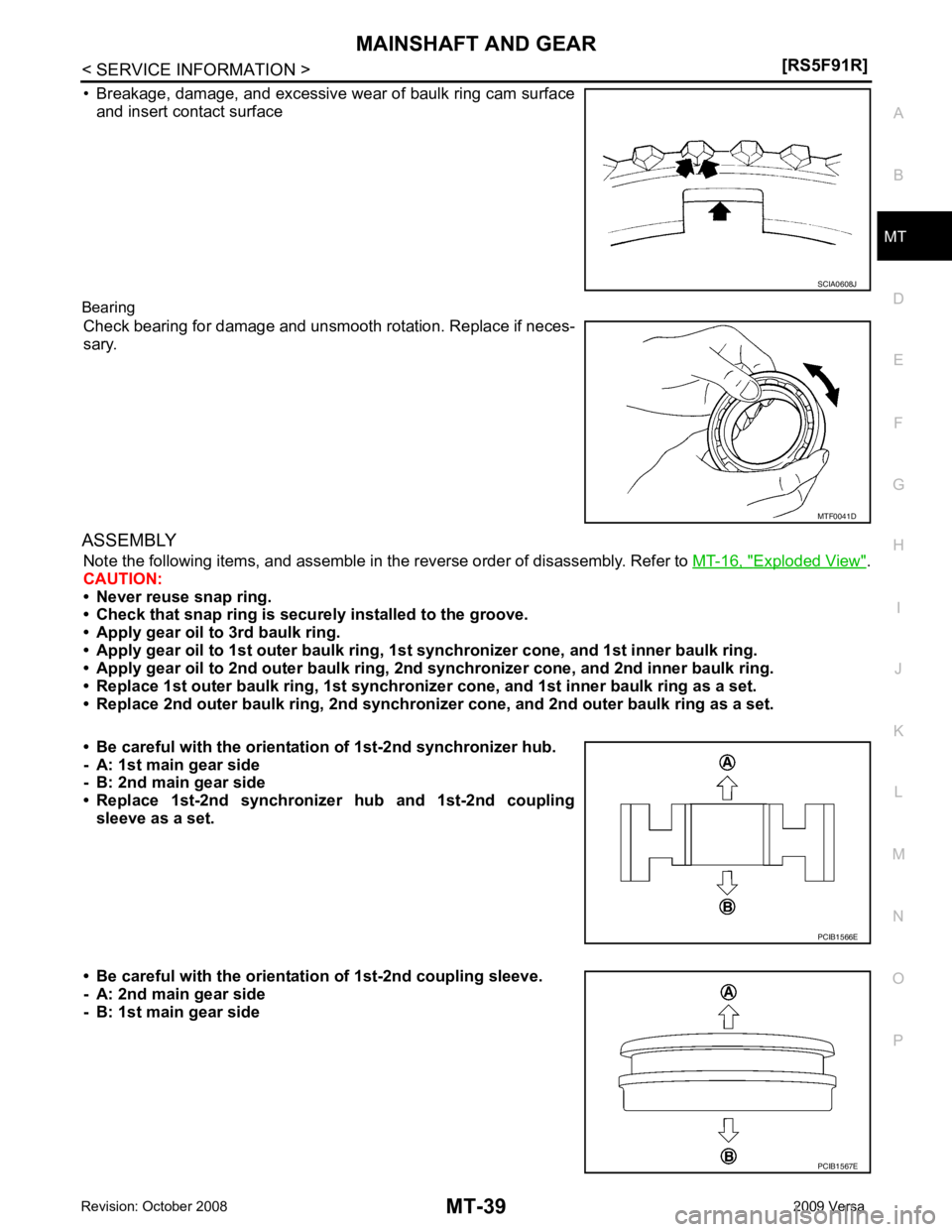
• Breakage, damage, and excessive wear of baulk ring cam surface
and insert contact surface
Bearing Check bearing for damage and unsmooth rotation. Replace if neces-
sary.
ASSEMBLY Note the following items, and assemble in t he reverse order of disassembly. Refer to MT-16, " Exploded View " .
CAUTION:
• Never reuse snap ring.
• Check that snap ring is secu rely installed to the groove.
• Apply gear oil to 3rd baulk ring.
• Apply gear oil to 1st outer baulk ring, 1st synchronizer cone, and 1st inner baulk ring.
• Apply gear oil to 2nd outer baulk ring, 2n d synchronizer cone, and 2nd inner baulk ring.
• Replace 1st outer baulk ring, 1st synchronize r cone, and 1st inner baulk ring as a set.
• Replace 2nd outer baulk ring, 2nd synchronize r cone, and 2nd outer baulk ring as a set.
• Be careful with the orientation of 1st-2nd synchronizer hub.
- A: 1st main gear side
- B: 2nd main gear side
• Replace 1st-2nd synchronize r hub and 1st-2nd coupling
sleeve as a set.
• Be careful with the orientation of 1st-2nd coupling sleeve.
- A: 2nd main gear side
- B: 1st main gear side MTF0041D
Page 3872 of 4331
![NISSAN TIIDA 2009 Service Repair Manual MT-78< SERVICE INFORMATION >
[RS6F94R]
INPUT SHAFT AND GEARS
• Damage, peeling, bend, uneven wear, and distortion of shaft.
• Excessive wear, damage, and peeling of gear.
Synchronizer
• Synchron NISSAN TIIDA 2009 Service Repair Manual MT-78< SERVICE INFORMATION >
[RS6F94R]
INPUT SHAFT AND GEARS
• Damage, peeling, bend, uneven wear, and distortion of shaft.
• Excessive wear, damage, and peeling of gear.
Synchronizer
• Synchron](/manual-img/5/57398/w960_57398-3871.png)
MT-78< SERVICE INFORMATION >
[RS6F94R]
INPUT SHAFT AND GEARS
• Damage, peeling, bend, uneven wear, and distortion of shaft.
• Excessive wear, damage, and peeling of gear.
Synchronizer
• Synchronizer hub and coupling sleeve Check the following items and replace if necessary.
- Breakage, damage, and unusual wear on contact surface of cou-
pling sleeve, synchronizer hub, and insert key.
- Coupling sleeve and synchronizer hub move smoothly.
• Baulk ring Check contact surface of baulk ring cam and insert key for exces-
sive wear, uneven wear, bend, and damage. Replace if necessary.
Bearing
Check bearing for damage and unsmooth rotation. Replace if neces-
sary.
ASSEMBLY
Note the following procedures, and assemble in the reverse order of disassembly.
CAUTION:
• Replace transaxle assembly when replacing input shaft.
• Never reuse snap ring.
• Check that snap ring is securely installed in a groove.
• Replace 3rd-4th coupling sleeve and 3rd-4th synchronizer hub as a set. SCIA7736E
SCIA1753J
SCIA0608J
MTF0041D
Page 3984 of 4331

PG
N
O P
CONTENTS
POWER SUPPLY, GROUND & CIRCUIT ELEMENTS
SERVICE INFORMATION .. ..........................2
PRECAUTIONS .............................................. .....2
Precaution for Supplemental Restraint System
(SRS) "AIR BAG" and "SEAT BELT PRE-TEN-
SIONER" ............................................................. ......
2
POWER SUPPLY ROUTING CIRCUIT .......... .....3
Schematic ........................................................... ......3
Wiring Diagram - POWER - ................................ ......5
Fuse .................................................................... ....15
Fusible Link ......................................................... ....15
Circuit Breaker (Built Into BCM) .......................... ....15
Circuit Breaker .................................................... ....15
IPDM E/R (INTELLIGENT POWER DISTRI-
BUTION MODULE ENGINE ROOM) ............. ....16
System Description ............................................. ....16
CAN Communication System Description ........... ....17
Function of Detecting Igni tion Relay Malfunction ....17
CONSULT-III Function (IPDM E/R) ..................... ....17
Auto Active Test .................................................. ....19
IPDM E/R Terminal Arrangement - Type A ......... ....22
IPDM E/R Terminal Arrangement - Type B ......... ....23
Terminal and Reference Value for IPDM E/R ..... ....24
IPDM E/R Power/Ground Circuit Inspection ....... ....26
Inspection with CONSULT- III (Self-Diagnosis) .......27
Removal and Installation of IPDM E/R ....................27 GROUND CIRCUI
T ........................................... 29
Ground Distribution .............................................. ....29
HARNESS ................... ...................................... 38
Harness Layout ................................................... ....38
Wiring Diagram Codes (Cell Codes) ................... ....57
ELECTRICAL UNITS LOCATION .................... 60
Electrical Units Location ...................................... ....60
HARNESS CONNECTOR ................................. 64
Description ........................................................... ....64
ELECTRICAL UNITS ........................................ 67
Terminal Arrangement ......................................... ....67
STANDARDIZED RELAY ................................. 68
Description ........................................................... ....68
SUPER MULTIPLE JUNCTION (SMJ) ............. 70
Terminal Arrangement ......................................... ....70
FUSE BLOCK-JUNCTION BOX (J/B) .............. 72
Terminal Arrangement ......................................... ....72
FUSE AND FUSIBLE LINK BOX ...................... 73
Terminal Arrangement ......................................... ....73
Page 3998 of 4331

PG
N
O P
Fuse
INFOID:0000000004306651
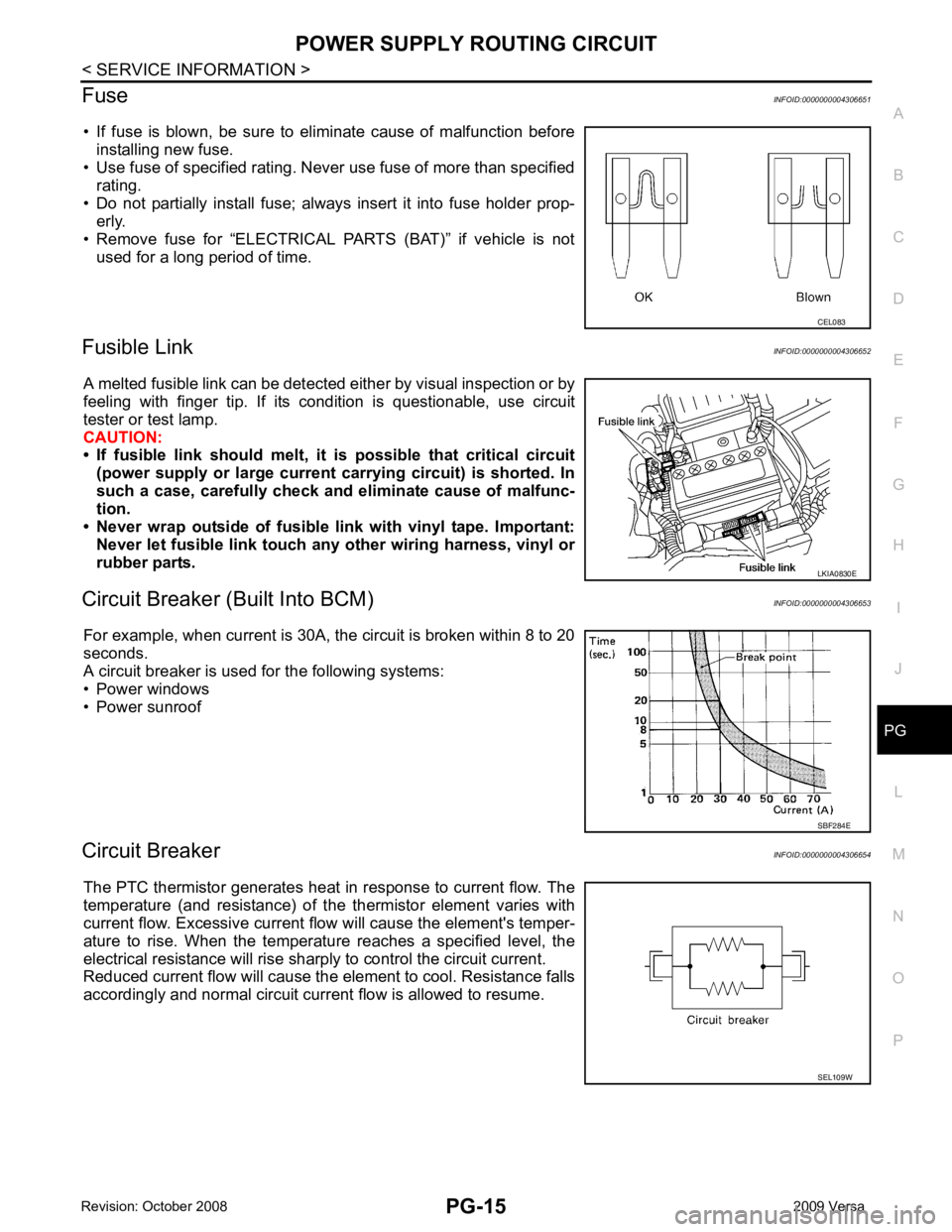
• If fuse is blown, be sure to eliminate cause of malfunction before installing new fuse.
• Use fuse of specified rating. Never use fuse of more than specified
rating.
• Do not partially install fuse; always insert it into fuse holder prop- erly.
• Remove fuse for “ELECTRICAL PARTS (BAT)” if vehicle is not
used for a long period of time.
Fusible Link INFOID:0000000004306652
A melted fusible link can be detected either by visual inspection or by
feeling with finger tip. If its condition is questionable, use circuit
tester or test lamp.
CAUTION:
• If fusible link should melt, it is possible that critical circuit
(power supply or large current carrying circuit) is shorted. In
such a case, carefully check and eliminate cause of malfunc-
tion.
• Never wrap outside of fusible li nk with vinyl tape. Important:
Never let fusible link touch any other wiring harness, vinyl or
rubber parts.
Circuit Breaker (B uilt Into BCM) INFOID:0000000004306653
For example, when current is 30A, the circuit is broken within 8 to 20
seconds.
A circuit breaker is used for the following systems:
• Power windows
• Power sunroof
Circuit Breaker INFOID:0000000004306654
The PTC thermistor generates heat in response to current flow. The
temperature (and resistance) of t he thermistor element varies with
current flow. Excessive current flow will cause the element's temper-
ature to rise. When the temperature reaches a specified level, the
electrical resistance will rise shar ply to control the circuit current.
Reduced current flow will cause the element to cool. Resistance falls
accordingly and normal circuit current flow is allowed to resume. LKIA0830E
SEL109W