Page 3922 of 4331

MTC
N
O P
OK >> GO TO 11.
NG >> Repair harness or connector. OK >> Replace the front blower motor resistor. Refer to
MTC-66, " Removal and Installation " .
NG >> Replace front air control. Refer to MTC-58, " Removal and Installation " .
Magnet Clutch Circuit (If Equipped) INFOID:0000000004307072
SYMPTOM: Magnet clutch does not engage.
INSPECTION FLOW YES >> GO TO 3.
NO >> GO TO 2. Operational Check " .
Does another symptom exist? YES >> Refer to
MTC-22, " How to Perform Trouble Diagnosis for Quick and Accurate Repair " .
NO >> System OK. Checking " (HR16DE) or
EM-136, " Checking Drive Belts "
(MR18DE).
OK or NG OK >> GO TO 5.
NG >> Adjust or replace A/C compressor belt. Refer to EM-15, " Removal and Installation " (HR16DE) or
EM-136, " Removal and Installation " (MR18DE).
Insufficient Cooling " .
OK or NG OK >> GO TO 6.
NG >> Perform trouble diagnosis for unusual pressure. Refer to MTC-45, " Insufficient Cooling " .
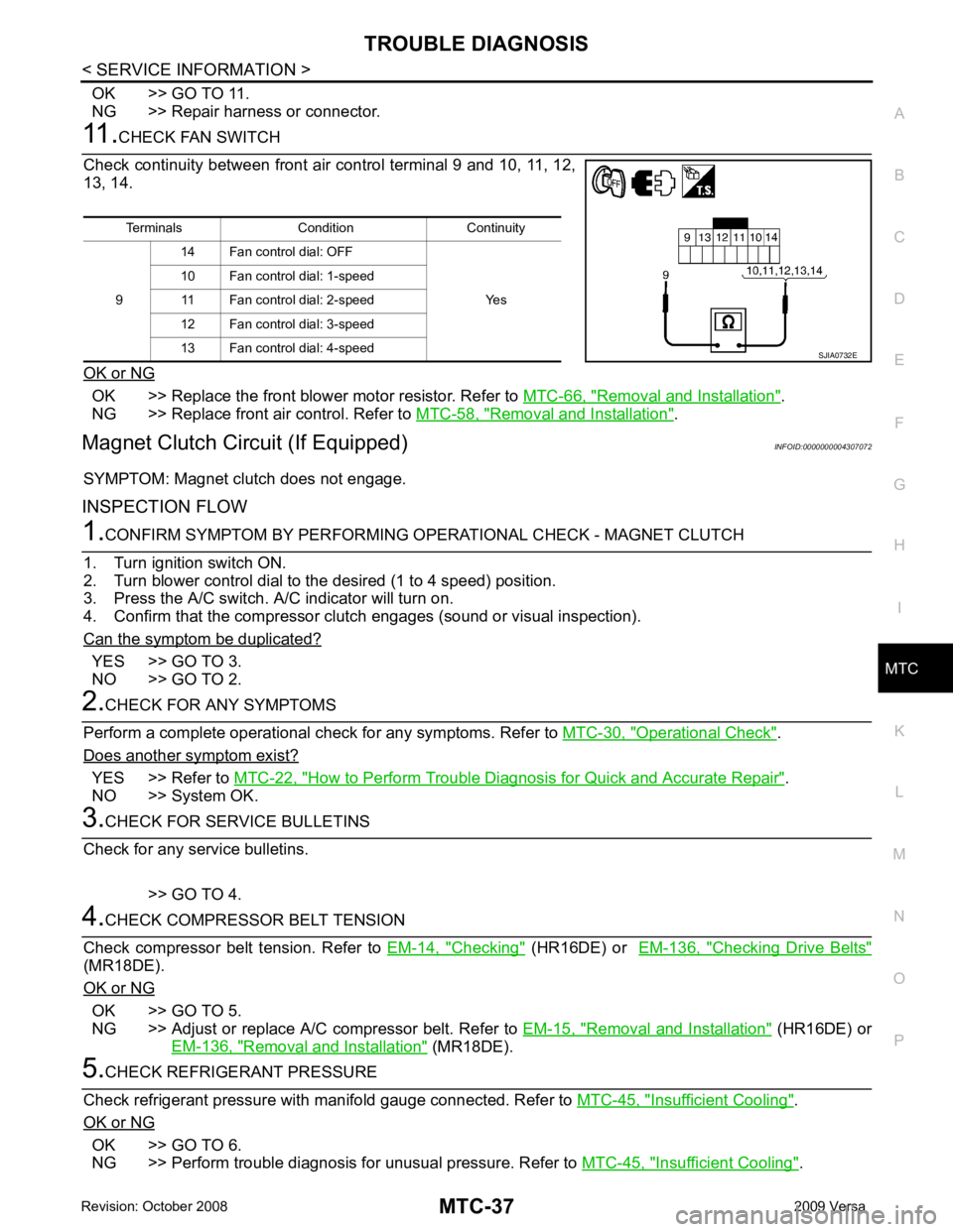
Terminals Condition Continuity
9 14 Fan control dial: OFF
Yes
10 Fan control dial: 1-speed
11 Fan control dial: 2-speed
12 Fan control dial: 3-speed
13 Fan control dial: 4-speed
Page 3933 of 4331
Removal and Installation " *2
MTC-33, " Front Blower Motor Circuit " *3
MTC-78, " Removal and Installation of
Compressor - HR16DE " or
MTC-80, " Removal and Installation of Com-
pressor - MR18DE "
*4
EM-14, " Checking " (HR16DE)
EM- 136, " Checking Drive Belts "
(MR18DE) *5
MTC-78, " Removal and Installation of
Compressor - HR16DE " or
MTC-80, " Removal and Installation of Com-
pressor - MR18DE "
Page 3936 of 4331

MTC
N
O P
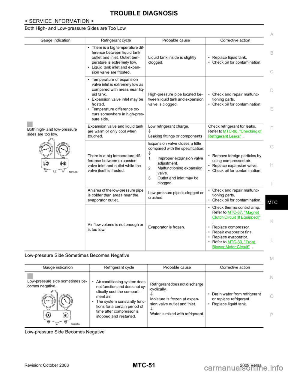
Both High- and Low-pressure Sides are Too Low
Low-pressure Side Some times Becomes Negative
Low-pressure Side Becomes Negative Gauge indication Refrigerant cycle Probable cause Corrective action
Both high- and low-pressure
sides are too low. • There is a big temperature dif-
ference between liquid tank
outlet and inlet. Outlet tem-
perature is extremely low.
• Liquid tank inlet and expan- sion valve are frosted. Liquid tank inside is slightly
clogged. • Replace liquid tank.
• Check oil for contamination.
• Temperature of expansion valve inlet is extremely low as
compared with areas near liq-
uid tank.
• Expansion valve inlet may be
frosted.
• Temperature difference oc- curs somewhere in high-pres-
sure side. High-pressure pipe located be-
tween liquid tank and expansion
valve is clogged. • Check and repair malfunc-
tioning parts.
• Check oil for contamination.
Expansion valve and liquid tank
are warm or only cool when
touched. Low refrigerant charge.
↓
Leaking fittings or components Check refrigerant for leaks.
Refer to MTC-86, " Checking of
Refrigerant Leaks " .
There is a big temperature dif-
ference between expansion
valve inlet and outlet while the
valve itself is frosted. Expansion valve closes a little
compared with the specification.
↓
1. Improper expansion valve
adjustment.
2. Malfunctioning expansion valve.
3. Outlet and inlet may be clogged. • Remove foreign particles by
using compressed air.
• Replace expansion valve.
• Check oil for contamination.
An area of the low-pressure pipe
is colder than areas near the
evaporator outlet. Low-pressure pipe is clogged or
crushed. • Check and repair malfunc-
tioning parts.
• Check oil for contamination.
Air flow volume is not enough or
is too low. Evaporator is frozen.• Check thermo control amp.
Refer to MTC-37, " Magnet
Clutch Circuit (If Equipped) "
.
• Replace compressor.
• Repair evaporator fins.
• Replace evaporator.
• Refer to MTC-33, " Front
Blower Motor Circuit " .
Page 3947 of 4331
Component Parts " .
2. Remove side ventilator duct (right). Refer to MTC-69, " Removal and Installation " .
3. Disconnect blower motor connector (1).
4. Push the flange holding hook (A) toward the blower motor (2), then rotate the blower motor (2) clockwise and remove it from
the A/C unit assembly.
CAUTION:
When blower fan and blower motor are assembled, the bal-
ance is adjusted, do not di sassemble to replace the individ-
ual parts.
INSTALLATION
Installation is in the reverse order of removal.
CAUTION:
Rotate the blower motor until the blower motor fl ange holding hook locks securely into the A/C unit
assembly.
Page:
< prev 1-8 9-16 17-24