2009 NISSAN TIIDA blower motor
[x] Cancel search: blower motorPage 3422 of 4331

LAN
N
O P
Engine status signal T R
Fuel consumption monitor signal T R
Malfunction indicator lamp signal T R
Wide open throttle position signal T R R
A/C switch signal R T
Blower fan motor switch signal R T
Buzzer output signal T R
T R
Day time running light request signal *3
T R
Door lock/unlock status signal T R
Door switch signal T R R R
Front wiper request signal T R
High beam request signal T R R
Horn chirp signal T R
Ignition switch signal T R
Low beam request signal T R
Position lights request signal T R R
Rear window defogger switch signal T R
Sleep/wake up signal R T
T R R R
Theft warning horn request signal T R
Tire pressure signal *4
T R
Trunk open/close status signal T R
Turn indicator signal T R
EPS operation signal R T
EPS warning lamp signal T R
Door lock/unlock/trunk open request signal R T
Hazard request signal R T
Ignition knob switch signal R T
KEY warning lamp signal T R
LOCK warning lamp signal T R
Panic alarm request signal R T
Fuel level sensor signal R T
Overdrive control switch signal T R R
P/N range signal T R
Stop lamp switch signal T R R
Vehicle speed signal R R R R T
R R R T R
R*5
T*5
ABS warning lamp signal R T
Brake warning lamp signal R T
A/T check indicator signal R T Signal name/Connecting unitECM
BCM EPS
I-KEY
M&AABS
TCM *1
TCM *2
IPDM-E
Page 3886 of 4331

MTC
N
O P
CONTENTS
MANUAL AIR CONDITIONER
SERVICE INFORMATION .. ..........................3
PRECAUTIONS .............................................. .....3
Precaution for Supplemental Restraint System
(SRS) "AIR BAG" and "SEAT BELT PRE-TEN-
SIONER" ............................................................. ......
3
Precaution Necessary fo r Steering Wheel Rota-
tion After Battery Disconnect ............................... ......
3
Precaution for Procedure without Cowl Top Cover ......4
Precaution for Working with HFC-134a (R-134a) ......4
General Refrigerant Precaution .......................... ......4
Oil Precaution ...................................................... ......5
Precaution for Refrigeran t Connection ......................5
Precaution for Service of Compressor ................ ......7
Precaution for Service Equipment ....................... ......8
Precaution for Leak Detection Dye ..................... ......9
PREPARATION .............................................. ....11
HFC-134a (R-134a) Service Tool and Equipment ....11
Commercial Service Tool .................................... ....13
REFRIGERATION SYSTEM .......................... ....15
Refrigerant Cycle ................................................ ....15
Refrigerant System Protec tion ................................15
Component Part Location ................................... ....16
OIL .................................................................. ....17
Maintenance of Oil Quantity in Compressor ....... ....17
AIR CONDITIONER CONTROL ..................... ....19
Control Operation ................................................ ....19
Discharge Air Flow .............................................. ....20
System Description ............................................. ....20
TROUBLE DIAGNOSIS ................................. ....22
CONSULT-II Function (BCM) .............................. ....22
How to Perform Trouble Diagnosis for Quick and
Accurate Repair ........... ...........................................
22
Component Parts and Harness Connector Loca-
tion ...................................................................... ....
23
Schematic ........................................................... ....25
Wiring Diagram - Heater - ................................... ....26 Wiring Diagram - A/C,M - ....................................
....27
Operational Check ............................................... ....30
Mode Door ........................................................... ....31
Air Mix Door ......................................................... ....32
Intake Door .......................................................... ....33
Front Blower Motor Circuit .......................................33
Magnet Clutch Circuit (If Equipped) ..................... ....37
Insufficient Cooling .............................................. ....45
Insufficient Heating .............................................. ....52
Noise ................................................................... ....53
CONTROLLER .................................................. 55
Removal and Installation ..................................... ....55
Disassembly and Assembly ................................. ....56
THERMO CONTROL AMPLIFIER .................... 57
Removal and Installation ..................................... ....57
A/C UNIT ASSEMBLY ...................................... 58
Removal and Installation ..................................... ....58
Disassembly and Assembly ................................. ....60
BLOWER MOTOR ............................................ 62
Removal and Installation ..................................... ....62
INTAKE DOOR .................................................. 63
Intake Door Cable Adjustment ............................. ....63
AIR MIX DOOR ................................................. 64
Air Mix Door Cable Adjustment ........................... ....64
MODE DOOR .................................................... 65
Mode Door Cable Adjustment ............................. ....65
BLOWER FAN RESISTOR ............................... 66
Removal and Installation ..................................... ....66
HEATER CORE ................................................. 67
Removal and Installation ..................................... ....67
AIR CONDITIONER FILTER ............................. 68
Removal and Installation ..................................... ....68
Page 3907 of 4331
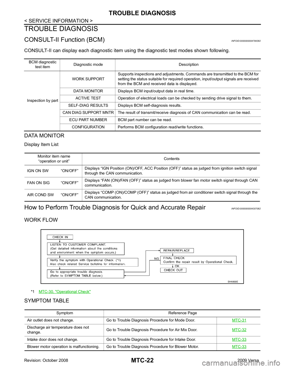
Monitor item name
“operation or unit” Contents
IGN ON SW “ON/OFF” Displays “IGN Position (ON)/OFF, ACC Position (OFF)” status as judged from ignition switch signal
through the CAN communication.
FAN ON SIG “ON/OFF” Displays “FAN (ON)/FAN (OFF)” status as judged from blower fan motor switch signal through CAN
communication.
AIR COND SW “ON/OFF” Displays “COMP (ON)/COMP (OFF)” status as judged from air conditioner switch signal through the
CAN communication. *1
MTC-30, " Operational Check "
Discharge air temperature does not
change. Go to Trouble Diagnosis Procedure for Air Mix Door.
MTC-32Intake door does not change. Go to Trouble Diagnosis Procedure for Intake Door.
MTC-33Blower motor operation is malfunctioning. Go to Trouble Diagnosis Procedure for Blower Motor.
MTC-33
Page 3916 of 4331
MTC
N
O P
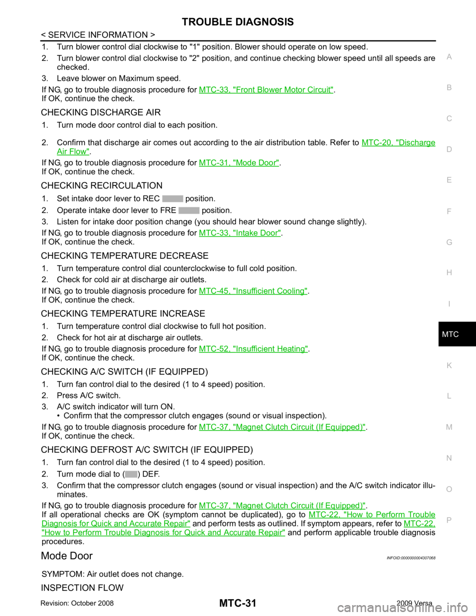
1. Turn blower control dial clockwise to "1" position. Blower should operate on low speed.
2. Turn blower control dial clockwise to "2" position, and continue checking blower speed until all speeds are
checked.
3. Leave blower on Maximum speed.
If NG, go to trouble diagnosis procedure for MTC-33, " Front Blower Motor Circuit " .
If OK, continue the check.
CHECKING DISCHARGE AIR 1. Turn mode door control dial to each position.
2. Confirm that discharge air comes out accord ing to the air distribution table. Refer to MTC-20, " Discharge
Air Flow " .
If NG, go to trouble diagnosis procedure for MTC-31, " Mode Door " .
If OK, continue the check.
CHECKING RECIRCULATION 1. Set intake door lever to REC position.
2. Operate intake door lever to FRE position.
3. Listen for intake door position change (you should hear blower sound change slightly).
If NG, go to trouble diagnosis procedure for MTC-33, " Intake Door " .
If OK, continue the check.
CHECKING TEMPERATURE DECREASE 1. Turn temperature control dial counterclockwise to full cold position.
2. Check for cold air at discharge air outlets.
If NG, go to trouble diagnosis procedure for MTC-45, " Insufficient Cooling " .
If OK, continue the check.
CHECKING TEMPERATURE INCREASE 1. Turn temperature control dial clockwise to full hot position.
2. Check for hot air at discharge air outlets.
If NG, go to trouble diagnosis procedure for MTC-52, " Insufficient Heating " .
If OK, continue the check.
CHECKING A/C SWITCH (IF EQUIPPED) 1. Turn fan control dial to the desired (1 to 4 speed) position.
2. Press A/C switch.
3. A/C switch indicator will turn ON. • Confirm that the compressor clutch engages (sound or visual inspection).
If NG, go to trouble diagnosis procedure for MTC-37, " Magnet Clutch Circuit (If Equipped) " .
If OK, continue the check.
CHECKING DEFROST A/C SWITCH (IF EQUIPPED) 1. Turn fan control dial to the desired (1 to 4 speed) position.
2. Turn mode dial to ( ) DEF.
3. Confirm that the compressor clutch engages (sound or vi sual inspection) and the A/C switch indicator illu-
minates.
If NG, go to trouble diagnosis procedure for MTC-37, " Magnet Clutch Circuit (If Equipped) " .
If all operational checks are OK (symptom cannot be duplicated), go to MTC-22, " How to Perform Trouble
Diagnosis for Quick and Accurate Repair " and perform tests as outlined. If symptom appears, refer to
MTC-22," How to Perform Trouble Diagnosis for Quick and Accurate Repair " and perform applicable trouble diagnosis
procedures.
Mode Door INFOID:0000000004307068
SYMPTOM: Air outlet does not change.
INSPECTION FLOW
Page 3918 of 4331
MTC
N
O P
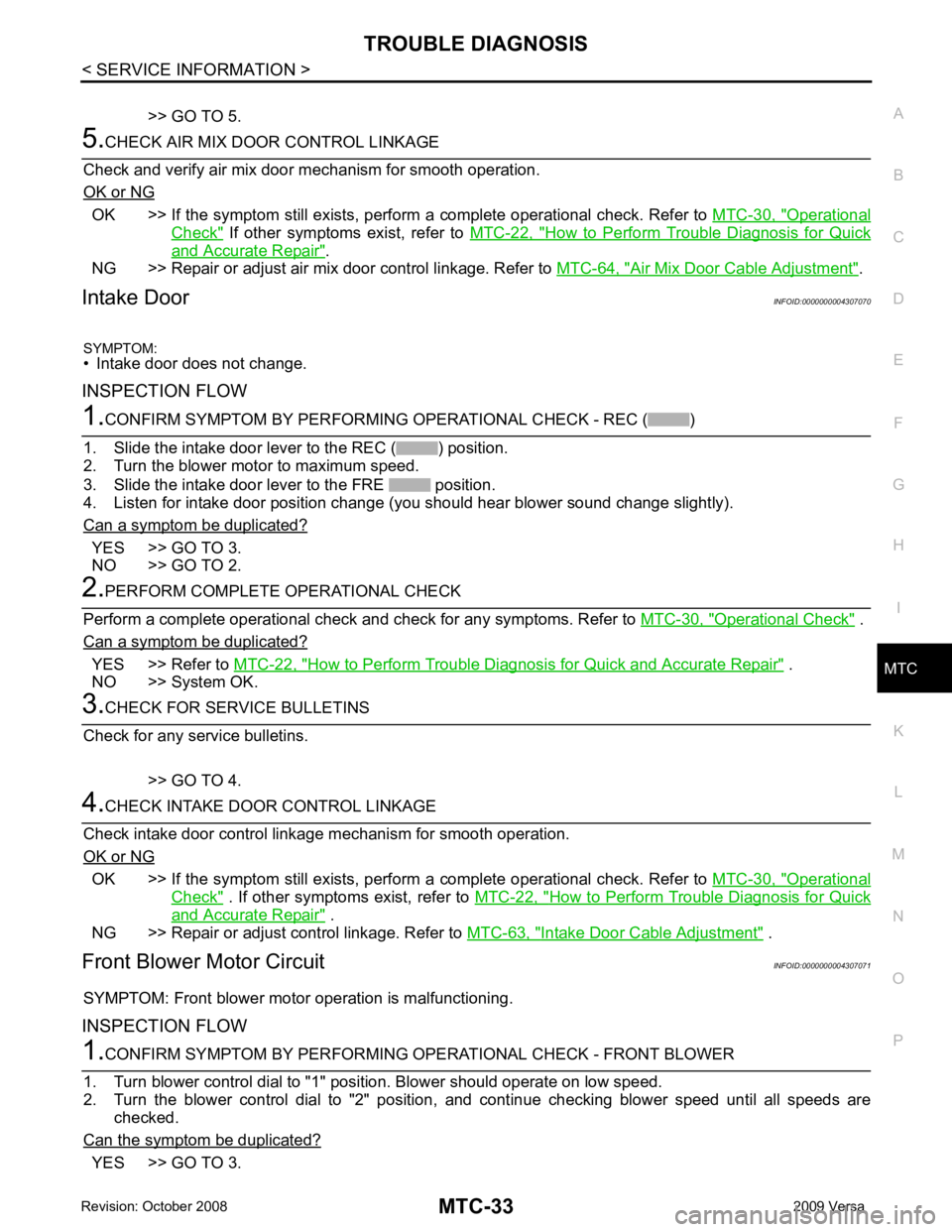
>> GO TO 5. OK >> If the symptom still exists, perform a complete operational check. Refer to
MTC-30, " Operational
Check " If other symptoms exist, refer to
MTC-22, " How to Perform Trouble Diagnosis for Quick
and Accurate Repair " .
NG >> Repair or adjust air mix door control linkage. Refer to MTC-64, " Air Mix Door Cable Adjustment " .
Intake Door INFOID:0000000004307070
SYMPTOM:
• Intake door does not change.
INSPECTION FLOW YES >> GO TO 3.
NO >> GO TO 2. Operational Check " .
Can a symptom be duplicated? YES >> Refer to
MTC-22, " How to Perform Trouble Diagnosis for Quick and Accurate Repair " .
NO >> System OK. OK >> If the symptom still exists, perform a complete operational check. Refer to
MTC-30, " Operational
Check " . If other symptoms exist, refer to
MTC-22, " How to Perform Trouble Diagnosis for Quick
and Accurate Repair " .
NG >> Repair or adjust control linkage. Refer to MTC-63, " Intake Door Cable Adjustment " .
Front Blower Motor Circuit INFOID:0000000004307071
SYMPTOM: Front blower motor operation is malfunctioning.
INSPECTION FLOW YES >> GO TO 3.
Page 3919 of 4331
Operational Check " .
Can a symptom be duplicated? YES >> Refer to
MTC-22, " How to Perform Trouble Diagnosis for Quick and Accurate Repair " .
NO >> System OK. OK >> If the symptom still exists, perform
a complete operational check. Refer to MTC-30, " Operational
Check " . If other symptoms exist, refer to
MTC-22, " How to Perform Trouble Diagnosis for Quick
and Accurate Repair " .
NG >> Repair as necessary.
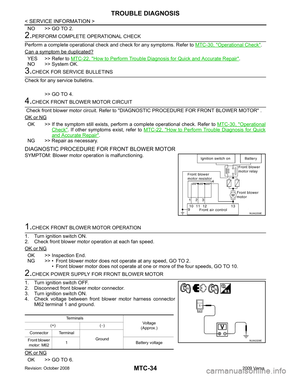
DIAGNOSTIC PROCEDURE FOR FRONT BLOWER MOTOR
SYMPTOM: Blower motor operation is malfunctioning. OK >> Inspection End.
NG >> • Front blower motor does not operate at any speed, GO TO 2.
• Front blower motor does not operate at one or more of the four speeds, GO TO 10.OK >> GO TO 6.
Page 3920 of 4331
![NISSAN TIIDA 2009 Service Repair Manual MTC
N
O P
NG >> Check power supply circuit and 15A fuses [Nos. 15 and 17, located in the fuse block (J/B)].
Refer to PG-3, " Schematic " .
• If fuses are OK, reinstall fuses and GO T NISSAN TIIDA 2009 Service Repair Manual MTC
N
O P
NG >> Check power supply circuit and 15A fuses [Nos. 15 and 17, located in the fuse block (J/B)].
Refer to PG-3, " Schematic " .
• If fuses are OK, reinstall fuses and GO T](/manual-img/5/57398/w960_57398-3919.png)
MTC
N
O P
NG >> Check power supply circuit and 15A fuses [Nos. 15 and 17, located in the fuse block (J/B)].
Refer to PG-3, " Schematic " .
• If fuses are OK, reinstall fuses and GO TO 3.
• If fuses are NG, replace fuse and check harness for short circuit. Repair or replace if necessary. OK >> GO TO 4.
NG >> Repair harness or connector. OK >> GO TO 5.
NG >> Repair harness or connector. OK >> Replace blower motor relay.
NG >> Repair harness or connector. OK >> GO TO 7.
NG >> Replace front blower motor. Refer to MTC-62, " Removal
and Installation " .
Page 3921 of 4331
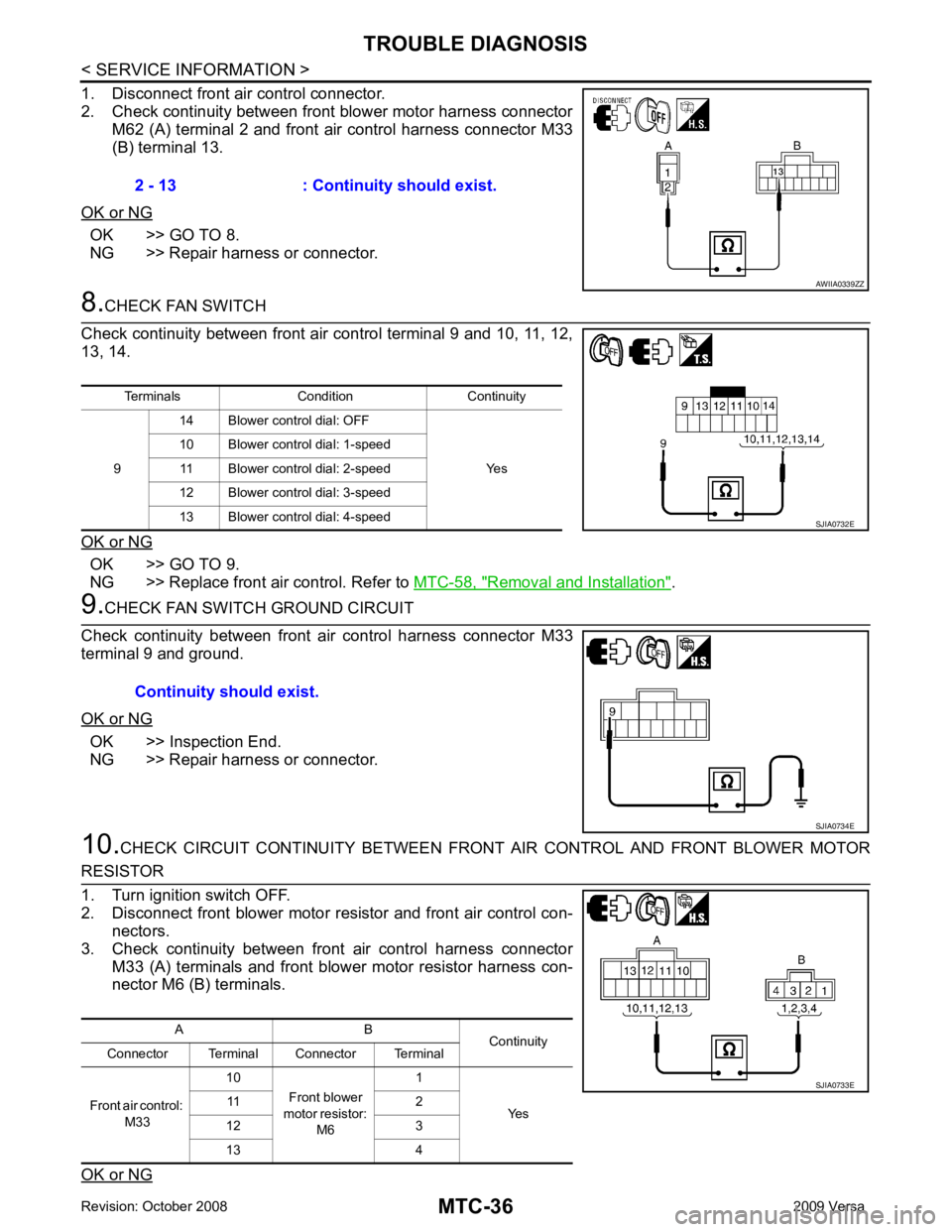
OK >> GO TO 8.
NG >> Repair harness or connector. OK >> GO TO 9.
NG >> Replace front air control. Refer to MTC-58, " Removal and Installation " .
OK >> Inspection End.
NG >> Repair harness or connector.
10. CHECK CIRCUIT CONTINUITY BE TWEEN FRONT AIR CONTROL AND FRONT BLOWER MOTOR