2009 NISSAN TIIDA maintenance
[x] Cancel search: maintenancePage 1133 of 4331

CVT
N
O P
PRECAUTIONS
Precaution for Supplemental Restraint System (SRS) "AIR BAG" and "SEAT BELT
PRE-TENSIONER" INFOID:0000000004800720
The Supplemental Restraint System such as “A IR BAG” and “SEAT BELT PRE-TENSIONER”, used along
with a front seat belt, helps to reduce the risk or severi ty of injury to the driver and front passenger for certain
types of collision. This system includes seat belt switch inputs and dual stage front air bag modules. The SRS
system uses the seat belt switches to determine the front air bag deployment, and may only deploy one front
air bag, depending on the severity of a collision and w hether the front occupants are belted or unbelted.
Information necessary to service the system safely is included in the SRS and SB section of this Service Man-
ual.
WARNING:
• To avoid rendering the SRS inoper ative, which could increase the risk of personal injury or death in
the event of a collision which would result in air bag inflation, all maintenance must be performed by
an authorized NISSAN/INFINITI dealer.
• Improper maintenance, including in correct removal and installation of the SRS can lead to personal
injury caused by unintentional act ivation of the system. For removal of Spiral Cable and Air Bag
Module, see the SRS section.
• Do not use electrical test equipm ent on any circuit related to the SRS unless instructed to in this
Service Manual. SRS wiring harnesses can be identi fied by yellow and/or orange harnesses or har-
ness connectors.
• When working near the Airbag Diagnosis Sensor Un it or other Airbag System sensors with the Igni-
tion ON or engine running, DO NOT use air or el ectric power tools or strike near the sensor(s) with a
hammer. Heavy vibration could activate the sensor( s) and deploy the air bag(s), possibly causing
serious injury.
• When using air or electric power tools or hammers , always switch the Ignition OFF, disconnect the
battery, and wait at least 3 minutes before performing any service.
Precaution Necessary for Steering Wh eel Rotation After Battery Disconnect
INFOID:0000000004305562
NOTE:
• This Procedure is applied only to models with Intell igent Key system and NVIS/IVIS (NISSAN/INFINITI
VEHICLE IMMOBILIZER SYSTEM - NATS).
• Remove and install all control units after disconnecti ng both battery cables with the ignition knob in the
″ LOCK ″ position.
• Always use CONSULT-III to perform self-diagnosis as a part of each function inspection after finishing work.
If DTC is detected, perform trouble diagnosis according to self-diagnostic results.
For models equipped with the Intelligent Key system and NVIS/IVIS, an electrically controlled steering lock
mechanism is adopted on the key cylinder.
For this reason, if the battery is disconnected or if the battery is discharged, the steering wheel will lock and
steering wheel rotation will become impossible.
If steering wheel rotation is required when battery pow er is interrupted, follow the procedure below before
starting the repair operation.
OPERATION PROCEDURE 1. Connect both battery cables. NOTE:
Supply power using jumper cables if battery is discharged.
2. Use the Intelligent Key or mechanical key to turn the ignition switch to the ″ACC ″ position. At this time, the
steering lock will be released.
3. Disconnect both battery cables. The steering lock will remain released and the steering wheel can be
rotated.
4. Perform the necessary repair operation.
5. When the repair work is completed, return the ignition switch to the ″LOCK ″ position before connecting
the battery cables. (At this time, the steering lock mechanism will engage.)
6. Perform a self-diagnosis check of al l control units using CONSULT-III.
Page 1447 of 4331

EC
NP
O
The 1st trip DTC (whose number is the same as the DT
C number) is displayed for the latest self-diagnostic
result obtained. If the ECM memory was cleared previously , and the 1st trip DTC did not recur, the 1st trip DTC
will not be displayed.
If a malfunction is detected during the 1st trip, the 1st trip DTC is stored in the ECM memory. The MIL will not
light up (two trip detection logic). If the same malfunc tion is not detected in the 2nd trip (meeting the required
driving pattern), the 1st trip DTC is cleared from the ECM memory. If the same malfunction is detected in the
2nd trip, both the 1st trip DTC and DTC are stored in t he ECM memory and the MIL lights up. In other words,
the DTC is stored in the ECM memory and the MIL light s up when the same malfunction occurs in two consec-
utive trips. If a 1st trip DTC is stored and a non-diagnostic operation is performed between the 1st and 2nd
trips, only the 1st trip DTC will continue to be stored. Fo r malfunctions that blink or light up the MIL during the
1st trip, the DTC and 1st trip DTC are stored in the ECM memory.
Procedures for clearing the DTC and the 1st trip DTC fr om the ECM memory are described in “How to Erase
DTC and 1st Trip DTC”.
For malfunctions in which 1st trip DTCs are displayed, refer to EC-475, " DTC Index " . These items are
required by legal regulations to c ontinuously monitor the system/component . In addition, the items monitored
non-continuously are also displayed on CONSULT-III.
1st trip DTC is specified in Service $07 of SAE J1979. 1st trip DTC detection occurs without lighting up the MIL
and therefore does not warn the driver of a malfunction. However, 1st trip DTC detection will not prevent the
vehicle from being tested, for example during Inspection/Maintenance (I/M) tests.
When a 1st trip DTC is detected, check, print out or write down and erase (1st trip) DTC and Freeze Frame
data as specified in Work Flow procedure Step 2, refer to EC-22, " Work Flow " . Then perform DTC CONFIR-
MATION PROCEDURE or Component Function Check to tr y to duplicate the malfunction. If the malfunction is
duplicated, the item requires repair.
Freeze Frame Data and 1st Trip Freeze Frame Data The ECM records the driving conditions such as fuel system status, calculated load value, engine coolant tem-
perature, short-term fuel trim, long-term fuel trim, engi ne speed, vehicle speed, absolute throttle position, base
fuel schedule and intake air temperature at the moment a malfunction is detected.
Data which are stored in the ECM memory, along with the 1st trip DTC, are called 1st trip freeze frame data.
The data, stored together with the DTC data, are ca lled freeze frame data and displayed on CONSULT-III or
GST. The 1st trip freeze frame data can only be di splayed on the CONSULT-III screen, not on the GST.
Only one set of freeze frame data (either 1st trip freez e frame data or freeze frame data) can be stored in the
ECM. 1st trip freeze frame data is stored in the ECM me mory along with the 1st trip DTC. There is no priority
for 1st trip freeze frame data and it is updated each time a different 1st trip DTC is detected. However, once
freeze frame data (2nd trip detection/MIL on) is stored in the ECM memory, 1st trip freeze frame data is no
longer stored. Remember, only one set of freeze frame data can be stored in the ECM. The ECM has the fol-
lowing priorities to update the data.
For example, the EGR malfunction (P riority: 2) was detected and the freeze frame data was stored in the 2nd
trip. After that when the misfire (Priority: 1) is detected in another trip, the freeze frame data will be updated
from the EGR malfunction to the misfire. The 1st trip freeze frame data is updated each time a different mal-
function is detected. There is no priority for 1st tr ip freeze frame data. However, once freeze frame data is
stored in the ECM memory, 1st trip freeze data is no longer stored (because only one freeze frame data or 1st
trip freeze frame data can be stored in the ECM). If fr eeze frame data is stored in the ECM memory and freeze
frame data with the same priority occurs later, the first (original) freeze frame data remains unchanged in the
ECM memory.
Both 1st trip freeze frame data and freeze frame dat a (along with the DTCs) are cleared when the ECM mem-
ory is erased. Procedures for clearing the ECM memory are described in “How to Erase DTC and 1st Trip
DTC”.
How to Read DTC and 1st Trip DTC DTC and 1st trip DTC can be read by the following methods.
With CONSULT-III
CONSULT-III displays the DTC in “SELF DIAGNOSTIC RESULT” mode.
Examples: P0340, P0850, P1148, etc. Priority Items
1 Freeze frame data Misfire — DTC: P0300 - P0304
Fuel Injection System Function — DTC: P0171, P0172
2 Except the above items (Includes A/T related items)
3 1st trip freeze frame data
Page 1848 of 4331
![NISSAN TIIDA 2009 Service Repair Manual EC-492< PRECAUTION >
[HR16DE]
PRECAUTIONS
PRECAUTION
PRECAUTIONS
Precaution for Supplemental Restraint Syst em (SRS) "AIR BAG" and "SEAT BELT
PRE-TENSIONER" INFOID:0000000004786987
The Supplemental](/manual-img/5/57398/w960_57398-1847.png "NISSAN TIIDA 2009 Service Repair Manual EC-492< PRECAUTION >
[HR16DE]
PRECAUTIONS
PRECAUTION
PRECAUTIONS
Precaution for Supplemental Restraint Syst em (SRS) \"AIR BAG\" and \"SEAT BELT
PRE-TENSIONER\" INFOID:0000000004786987
The Supplemental")
EC-492< PRECAUTION >
[HR16DE]
PRECAUTIONS
PRECAUTION
PRECAUTIONS
Precaution for Supplemental Restraint Syst em (SRS) "AIR BAG" and "SEAT BELT
PRE-TENSIONER" INFOID:0000000004786987
The Supplemental Restraint System such as “A IR BAG” and “SEAT BELT PRE-TENSIONER”, used along
with a front seat belt, helps to reduce the risk or severi ty of injury to the driver and front passenger for certain
types of collision. This system includes seat belt switch inputs and dual stage front air bag modules. The SRS
system uses the seat belt switches to determine the front air bag deployment, and may only deploy one front
air bag, depending on the severity of a collision and w hether the front occupants are belted or unbelted.
Information necessary to service the system safely is included in the “SUPPLEMENTAL RESTRAINT SYS-
TEM” and “SEAT BELTS” of this Service Manual.
WARNING:
• To avoid rendering the SRS inopera tive, which could increase the risk of personal injury or death in
the event of a collision which would result in air bag inflation, all maintenance must be performed by
an authorized NISS AN/INFINITI dealer.
• Improper maintenance, including in correct removal and installation of the SRS, can lead to personal
injury caused by unintent ional activation of the system. For re moval of Spiral Cable and Air Bag
Module, see the “SUPPLEMEN TAL RESTRAINT SYSTEM”.
• Do not use electrical test equipmen t on any circuit related to the SRS unless instructed to in this
Service Manual. SRS wiring harn esses can be identified by yellow and/or orange harnesses or har-
ness connectors.
PRECAUTIONS WHEN USING POWER TOOLS (AIR OR ELECTRIC) AND HAMMERS
WARNING:
• When working near the Airbag Diagnosis Sensor Unit or other Airbag System sensors with the igni-
tion ON or engine running, DO NOT use air or electri c power tools or strike near the sensor(s) with a
hammer. Heavy vibration could activate the sensor( s) and deploy the air bag(s), possibly causing
serious injury.
• When using air or electric power tools or hammers , always switch the ignition OFF, disconnect the
battery, and wait at least 3 minu tes before performing any service.
Precaution for Procedure without Cowl Top Cover INFOID:0000000004786988
When performing the procedure after removing cowl top cover, cover
the lower end of windshield with urethane, etc.
On Board Diagnosis (OBD) S ystem of Engine and A/T INFOID:0000000004780394
The ECM has an on board diagnostic system. It will light up the malfunction indicator lamp (MIL) to warn the
driver of a malfunction causing emission deterioration.
CAUTION:
• Be sure to turn the ignition sw itch OFF and disconnect the negative battery cable before any repair
or inspection work. The open/short circuit of re lated switches, sensors, solenoid valves, etc. will
cause the MIL to light up.
• Be sure to connect and lock the connectors secure ly after work. A loose (unlocked) connector will
cause the MIL to light up due to the open circuit. (Be sure the connector is free from water, grease,
dirt, bent terminals, etc.)
• Certain systems and components, especially those related to OBD, may use a new style slide-lock-
ing type harness connector. For descrip tion and how to disconnect, refer to PG-64, " Description " .PIIB3706J
Page 1857 of 4331
![NISSAN TIIDA 2009 Service Repair Manual EVAP LEAK CHECK
EC-501
< ON-VEHICLE MAINTENANCE >
[HR16DE] C
D E
F
G H
I
J
K L
M A EC
NP
O
5. Locate the leak using a leak detector [commercial service tool:
(J-41416)]. Refer to EC-74, " Sy](/manual-img/5/57398/w960_57398-1856.png "NISSAN TIIDA 2009 Service Repair Manual EVAP LEAK CHECK
EC-501
< ON-VEHICLE MAINTENANCE >
[HR16DE] C
D E
F
G H
I
J
K L
M A EC
NP
O
5. Locate the leak using a leak detector [commercial service tool:
(J-41416)]. Refer to EC-74, \" Sy")
EVAP LEAK CHECK
EC-501
< ON-VEHICLE MAINTENANCE >
[HR16DE] C
D E
F
G H
I
J
K L
M A EC
NP
O
5. Locate the leak using a leak detector [commercial service tool:
(J-41416)]. Refer to EC-74, " System Description " .
SEF200U
Page 1868 of 4331
![NISSAN TIIDA 2009 Service Repair Manual EC-512< SERVICE INFOMATION >
[MR TYPE 1]
PRECAUTIONS
PRECAUTIONS
Precaution for Supplemental Restraint Syst em (SRS) "AIR BAG" and "SEAT BELT
PRE-TENSIONER" INFOID:0000000004537013
The Supplemental](/manual-img/5/57398/w960_57398-1867.png "NISSAN TIIDA 2009 Service Repair Manual EC-512< SERVICE INFOMATION >
[MR TYPE 1]
PRECAUTIONS
PRECAUTIONS
Precaution for Supplemental Restraint Syst em (SRS) \"AIR BAG\" and \"SEAT BELT
PRE-TENSIONER\" INFOID:0000000004537013
The Supplemental")
EC-512< SERVICE INFOMATION >
[MR TYPE 1]
PRECAUTIONS
PRECAUTIONS
Precaution for Supplemental Restraint Syst em (SRS) "AIR BAG" and "SEAT BELT
PRE-TENSIONER" INFOID:0000000004537013
The Supplemental Restraint System such as “A IR BAG” and “SEAT BELT PRE-TENSIONER”, used along
with a front seat belt, helps to reduce the risk or severi ty of injury to the driver and front passenger for certain
types of collision. This system includes seat belt switch inputs and dual stage front air bag modules. The SRS
system uses the seat belt switches to determine the front air bag deployment, and may only deploy one front
air bag, depending on the severity of a collision and w hether the front occupants are belted or unbelted.
Information necessary to service the system safely is included in the “SUPPLEMENTAL RESTRAINT SYS-
TEM” and “SEAT BELTS” of this Service Manual.
WARNING:
• To avoid rendering the SRS inopera tive, which could increase the risk of personal injury or death in
the event of a collision which would result in air bag inflation, all maintenance must be performed by
an authorized NISS AN/INFINITI dealer.
• Improper maintenance, including in correct removal and installation of the SRS, can lead to personal
injury caused by unintent ional activation of the system. For re moval of Spiral Cable and Air Bag
Module, see the “SUPPLEMEN TAL RESTRAINT SYSTEM”.
• Do not use electrical test equipmen t on any circuit related to the SRS unless instructed to in this
Service Manual. SRS wiring harn esses can be identified by yellow and/or orange harnesses or har-
ness connectors.
PRECAUTIONS WHEN USING POWER TOOLS (AIR OR ELECTRIC) AND HAMMERS
WARNING:
• When working near the Airbag Diagnosis Sensor Unit or other Airbag System sensors with the igni-
tion ON or engine running, DO NOT use air or electri c power tools or strike near the sensor(s) with a
hammer. Heavy vibration could activate the sensor( s) and deploy the air bag(s), possibly causing
serious injury.
• When using air or electric power tools or hammers , always switch the ignition OFF, disconnect the
battery, and wait at least 3 minu tes before performing any service.
Precaution for Procedure without Cowl Top Cover INFOID:0000000004537014
When performing the procedure after removing cowl top cover, cover
the lower end of windshield with urethane, etc.
On Board Diagnosis (OBD) Syst em of Engine and A/T, CVT INFOID:0000000004537015
The ECM has an on board diagnostic system. It will light up the malfunction indicator lamp (MIL) to warn the
driver of a malfunction causing emission deterioration.
CAUTION:
• Be sure to turn the ignition sw itch OFF and disconnect the battery ground cable before any repair or
inspection work. The open/short circuit of related sw itches, sensors, solenoid valves, etc. will cause
the MIL to light up.
• Be sure to connect and lock the connectors secure ly after work. A loose (unlocked) connector will
cause the MIL to light up due to the open circuit. (Be sure the connector is free from water, grease,
dirt, bent terminals, etc.)
• Certain systems and components, especially those related to OBD, may use a new style slide-lock-
ing type harness connector. For descrip tion and how to disconnect, refer to PG-64, " Description " .
• Be sure to route and secure the harnesses properly after work. The interference of the harness with
a bracket, etc. may cause the MIL to li ght up due to the short circuit. PIIB3706J
Page 1901 of 4331
EC
NP
O
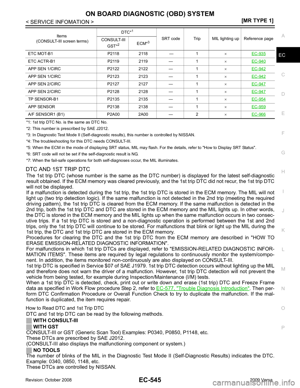
*1: 1st trip DTC No. is
the same as DTC No.
*2: This number is prescribed by SAE J2012.
*3: In Diagnostic Test Mode II (Self-diagnostic results), this number is controlled by NISSAN.
*4: The troubleshooting for this DTC needs CONSULT-III.
*5: When the ECM in the mode of displaying SRT status, MIL may flash. For the details, refer to "How to Display SRT Status".
*6: SRT code will not be set if the self-diagnostic result is NG.
*7: When the fail-safe operations for both self-diagnoses occur, the MIL illuminates.
DTC AND 1ST TRIP DTC The 1st trip DTC (whose number is the same as the DT C number) is displayed for the latest self-diagnostic
result obtained. If the ECM memory was cleared previously , and the 1st trip DTC did not recur, the 1st trip DTC
will not be displayed.
If a malfunction is detected during the 1st trip, the 1st trip DTC is stored in the ECM memory. The MIL will not
light up (two trip detection logic). If the same malfunc tion is not detected in the 2nd trip (meeting the required
driving pattern), the 1st trip DTC is cleared from the ECM memory. If the same malfunction is detected in the
2nd trip, both the 1st trip DTC and DTC are stored in t he ECM memory and the MIL lights up. In other words,
the DTC is stored in the ECM memory and the MIL light s up when the same malfunction occurs in two consec-
utive trips. If a 1st trip DTC is stored and a non-diagnostic operation is performed between the 1st and 2nd
trips, only the 1st trip DTC will continue to be stored. Fo r malfunctions that blink or light up the MIL during the
1st trip, the DTC and 1st trip DTC are stored in the ECM memory.
Procedures for clearing the DTC and the 1st trip DT C from the ECM memory are described in "HOW TO
ERASE EMISSION-RELATED DIAGNOSTIC INFORMATION".
For malfunctions in which 1st trip DTCs are displa yed, refer to "EMISSION-RELATED DIAGNOSTIC INFOR-
MATION ITEMS". These items are required by legal r egulations to continuously monitor the system/compo-
nent. In addition, the items monitored non-cont inuously are also displayed on CONSULT-III.
1st trip DTC is specified in Service $07 of SAE J1979. 1st trip DTC detection occurs without lighting up the MIL
and therefore does not warn the driver of a malfunction. However, 1st trip DTC detection will not prevent the
vehicle from being tested, for example during Inspection/Maintenance (I/M) tests.
When a 1st trip DTC is detected, check, print out or write down and erase (1st trip) DTC and Freeze Frame
data as specified in Work Flow procedure Step 2, refer to EC-577, " Trouble Diagnosis Introduction " . Then per-
form DTC Confirmation Procedure or Overall Function Che ck to try to duplicate the malfunction. If the mal-
function is duplicated, the item requires repair.
How to Read DTC and 1st Trip DTC DTC and 1st trip DTC can be read by the following methods.
WITH CONSULT-III
WITH GST
CONSULT-III or GST (Generic Scan Tool ) Examples: P0340, P0850, P1148, etc.
These DTCs are prescribed by SAE J2012.
(CONSULT-III also displays the malfunctioning component or system.)
NO TOOLS
The number of blinks of the MIL in the Diagnostic Test Mode II (Self-Diagnostic Results) indicates the DTC.
Example: 0340, 0850, 1148, etc.
These DTCs are controlled by NISSAN. ETC MOT-B1 P2118 2118 — 1
×EC-935 ETC ACTR-B1 P2119 2119 — 1
×EC-940 APP SEN 1/CIRC P2122 2122 — 1
×EC-942 APP SEN 1/CIRC P2123 2123 — 1
×EC-942 APP SEN 2/CIRC P2127 2127 — 1
×EC-947 APP SEN 2/CIRC P2128 2128 — 1
×EC-947 TP SENSOR-B1 P2135 2135 — 1
×EC-954 APP SENSOR P2138 2138 — 1
×EC-959 A/F SENSOR1 (B1) P2A00 2A00 — 2
×EC-966 Items
(CONSULT-III screen terms) DTC*
1
SRT code Trip MIL lighting up Reference page
CONSULT-III
GST* 2
ECM*3
Page 1922 of 4331
![NISSAN TIIDA 2009 Service Repair Manual EC-566< SERVICE INFOMATION >
[MR TYPE 1]
BASIC SERVICE PROCEDURE
BASIC SERVICE PROCEDURE
Basic Inspection INFOID:00000000045370431.
INSPECTION START
1. Check service records for any recent repairs tha](/manual-img/5/57398/w960_57398-1921.png "NISSAN TIIDA 2009 Service Repair Manual EC-566< SERVICE INFOMATION >
[MR TYPE 1]
BASIC SERVICE PROCEDURE
BASIC SERVICE PROCEDURE
Basic Inspection INFOID:00000000045370431.
INSPECTION START
1. Check service records for any recent repairs tha")
EC-566< SERVICE INFOMATION >
[MR TYPE 1]
BASIC SERVICE PROCEDURE
BASIC SERVICE PROCEDURE
Basic Inspection INFOID:00000000045370431.
INSPECTION START
1. Check service records for any recent repairs that ma y indicate a related malfunction, or a current need for
scheduled maintenance.
2. Open engine hood and check the following:
- Harness connectors for improper connections
- Wiring harness for improper connections, pinches and cut
- Vacuum hoses for splits, kinks and improper connections
- Hoses and ducts for leaks
- Air cleaner clogging
- Gasket
3. Confirm that electrical or mechanical loads are not applied.
- Headlamp switch is OFF.
- Air conditioner switch is OFF.
- Rear window defogger switch is OFF.
- Steering wheel is in the straight-ahead position, etc.
4. Start engine and warm it up until engine coolant temperature indicator points the middle of gauge.
Ensure engine stays below 1,000 rpm.
5. Run engine at about 2,000 rpm for about 2 minutes under no load.
6. Make sure that no DTC is displayed with CONSULT-III or GST.
OK or NG OK >> GO TO 3.
NG >> GO TO 2. 2.
REPAIR OR REPLACE
Repair or replace components as necessary according to corresponding Diagnostic Procedure.
>> GO TO 3. 3.
CHECK TARGET IDLE SPEED
With CONSULT-III
1. Run engine at about 2,000 rpm for about 2 minutes under no load. SEF983U
SEF976U
SEF977U
Page 1928 of 4331

Idle Air Volume Learning " .
VIN Registration INFOID:0000000004537046
DESCRIPTION
VIN Registration is an operation to registering VIN in ECM. It must be performed each time ECM is replaced.
NOTE:
Accurate VIN which is registered in ECM ma y be required for Inspection & Maintenance (I/M).
OPERATION PROCEDURE
With CONSULT-III
1. Check the VIN of the vehicle and note it. Refer to GI-43 .
2. Turn ignition switch ON and engine stopped.
3. Select “VIN REGISTRATION ” in “WORK SUPPORT” mode.
4. Follow the instruction of CONSULT-III display.
Accelerator Pedal Released Position Learning INFOID:0000000004537047
DESCRIPTION
Accelerator Pedal Released Position Learning is an operati on to learn the fully released position of the accel-
erator pedal by monitoring the accelerator pedal positi on sensor output signal. It must be performed each time
harness connector of accelerator pedal pos ition sensor or ECM is disconnected.
OPERATION PROCEDURE
1. Make sure that accelerator pedal is fully released.
2. Turn ignition switch ON and wait at least 2 seconds.
3. Turn ignition switch OFF and wait at least 10 seconds.
4. Turn ignition switch ON and wait at least 2 seconds.
5. Turn ignition switch OFF and wait at least 10 seconds.
Throttle Valve Clos ed Position Learning INFOID:0000000004537048
DESCRIPTION
Throttle Valve Closed Position Learning is an operation to l earn the fully closed position of the throttle valve by
monitoring the throttle position sensor output signal . It must be performed each time harness connector of
electric throttle control actuator or ECM is disconnected.
OPERATION PROCEDURE
1. Make sure that accelerator pedal is fully released.
2. Turn ignition switch ON.
3. Turn ignition switch OFF and wait at least 10 seconds. Make sure that throttle valve moves during above 10 seconds by confirming the operating sound.
Idle Air Volume Learning INFOID:0000000004537049
DESCRIPTION
Idle Air Volume Learning is an operation to learn the idle air volume that keeps each engine within the specific
range. It must be performed under any of the following conditions:
• Each time electric throttle control actuator or ECM is replaced.
• Idle speed or ignition timing is out of specification.
PREPARATION
Before performing Idle Air Volume Learning, make sure that all of the following conditions are satisfied.
Learning will be cancelled if any of the follo wing conditions are missed for even a moment.
• Battery voltage: More than 12.9V (At idle)
• Engine coolant temperature: 70 - 95 °C (158 - 203 °F)
• Park/neutral position (PNP) switch: ON
• Electric load switch: OFF