2009 NISSAN TIIDA power door
[x] Cancel search: power doorPage 4035 of 4331
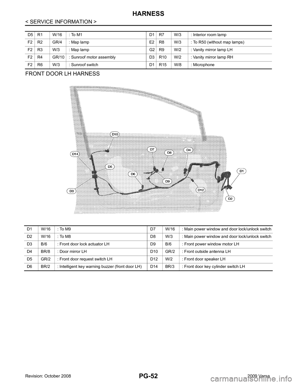
D1 W/16 : To M9 D7 W/16 : Main power window and door lock/unlock switch
D2 W/16 : To M8 D8 W/3 : Main power window and door lock/unlock switch
D3 B/6 : Front door lock actuator LH D9 B/6 : Front power window motor LH
D4 BR/8 : Door mirror LH D10 GR/2 : Front outside antenna LH
D5 GR/2 : Front door request switch LH D12 W/2 : Front door speaker LH
D6 BR/2 : Intelligent key warning buzzer (front door LH) D14 BR/3 : Front door key cylinder switch LH
Page 4040 of 4331

PG
N
O P
Wiring Diagram Codes (Cell Codes)
INFOID:0000000004306667
Use the chart below to find out what each wiring diagram code stands for.
Refer to the wiring diagram code in the alphabetical index to find the location (page number) of each wiring
diagram. D4 D405 W/4 : Back door lock assembly C2 D413 B/1 : Rear window defogger (-)
D4 D406 W/2 : Back door request switch F3 D414 — : Body ground
E2 D407 W/2 : High mounted stop lamp Code Section Wiring Diagram Name
ABS BRC Anti-lock Brake System
A/C,M MTC Manual Air Conditioner
APPS1 EC Accelerator Pe dal Position Sensor
A/F EC Air Fuel Ratio Sensor 1
A/FH EC Air Fuel Ratio Sensor 1 Heater
APPS2 EC Accelerator Pe dal Position Sensor
APPS3 EC Accelerator Pe dal Position Sensor
ASC/BS EC ASCD Brake Switch
ASC/SW EC ASCD Steering Switch
ASCBOF EC ASCD Brake Switch
ASCIND EC ASCD Indicator
AT/IND DI A/T Indicator Lamp
AUDIO AV Audio
BACK/L LT Back-up Lamp
BA/FTS AT A/T Fluid Temperature Sensor and TCM Power Supply
B/DOOR BL Back Door Opener
BRK/SW EC Brake Switch
CAN AT CAN Communication Line
CAN CVT CAN Comm unication Line
CAN EC CAN Communication Line
CAN LAN CAN System
CHARGE SC Charging System
CHIME DI Warning Chime
COOL/F EC Cooling Fan Control
COMBSW LT Combination Switch
CVTIND DI CVT Indicator Lamp
D/LOCK BL Power Door Lock
DEF GW Rear Window Defogger
DTRL LT Headlamp - Wi th Daytime Light System
ECTS EC Engine Coolant Temperature Sensor
ENGSS AT Engine Speed Signal
EPS STC Electronic Controlled Power Steering
ETC1 EC Electric Throttle Control Function
ETC2 EC Throttle Control Motor Relay
ETC3 EC Throttle Control Motor
F/FOG LT Front Fog Lamp
F/PUMP EC Fuel Pump
FTS AT A/T Fluid Temperature Sensor
FTS CVT CVT Fluid Temperature Sensor Circuit
FTTS EC Fuel Tank Temperature Sensor
FUEL EC Fuel Ignition System Function
HEATER MTC Heater System
Page 4082 of 4331

RF
N
O P
CONTENTS
ROOF
PRECAUTION ....... ........................................2
PRECAUTIONS .............................................. .....2
Precaution for Supplemental Restraint System
(SRS) "AIR BAG" and "SEAT BELT PRE-TEN-
SIONER" ............................................................. ......
2
Precaution Necessary fo r Steering Wheel Rota-
tion After Battery Disconnect ............................... ......
2
Precaution ........................................................... ......2
PREPARATION .... ........................................4
PREPARATION .............................................. .....4
Commercial Service Tool .................................... ......4
SYMPTOM DIAGNOSIS ..... ..........................5
SQUEAK AND RATTLE TROUBLE DIAG-
NOSES ........................ ........................................5
Work Flow ........................................................... ......5
Generic Squeak and Rattle Troubleshooting ...... ......7
Diagnostic Worksheet ......................................... ......9
FUNCTION DIAGNOSIS .. ............................11
TROUBLE DIAGNOSIS ................................. ....11 Component Parts and Harness Connector Loca-
tion ....................................................................... ....
11
System Description .............................................. ....11
CAN Communication System Description ........... ....13
Wiring Diagram - SROOF - .................................. ....14
Terminal and Reference Value for BCM ..................15
Terminal and Reference Value for Sunroof Motor
Assembly ............................................................. ....
16
Work Flow ............................................................ ....16
CONSULT-III Function (B CM) .................................16
Work Support ....................................................... ....17
Active Test ........................................................... ....17
Data Monitor ........................................................ ....17
Trouble Diagnosis Chart by Symptom ................. ....17
BCM Power Supply and Ground Circuit Inspection ....17
Sunroof Switch System Inspection ...................... ....17
Sunroof Motor Assembly Power Supply and
Ground Circuit Inspection .................................... ....
19
Door Switch Check .............................................. ....20
ON-VEHICLE REPAIR ..... ............................22
SUNROOF ......................................................... 22
Removal and Installation ..................................... ....22
Fitting Adjustment ................................................ ....27
Inspection ............................................................ ....28
Page 4093 of 4331

Work Support " .
ANTI-PINCH FUNCTION
The CPU (central processing unit) of sunroof motor as sembly monitors the sunroof motor operation and the
sunroof position (fully-closed or other ) by the signals from sunroof motor.
When sunroof motor detects an interruption during the following slide close and tilt down operation, sunroof
switch controls the motor for open and the sunroof will oper ate until it reaches full up position (during tilt down
operation) or 125 mm (4.92 in) or more in an open direction (during slide close operation).
• close operation and tilt down when igniti on switch is in the ON position.
• close operation and tilt down during retained power operation.
INITIALIZATION FAILURE CONDITIONS
Initialization and teaching of system should be conducted if the following conditions exist:
• sunroof will only move in the UP/CLOSE direction, having a step by step motion
• sunroof does not have any auto operation.
INITIALIZATION PROCEDURE
If the sunroof does not close or open automatically, use the following procedure to return sunroof operation to
normal.
1. Press the switch to the UP/CLOSE position to tilt t he sunroof up fully. When the sunroof reaches the full tilt
up position it will back up a few millimeters and stop.
2. Release the UP/CLOSE switch.
3. Within 5 seconds of releasing the UP/CLOSE sw itch, press and hold the UP/CLOSE switch again. The
sunroof will move to the full open position and back to the closed position.
NOTE:
If the UP/CLOSE switch is released anytime during th is teaching process, all learned profile data will be dis-
carded and the procedure will have to be started over.
4. Release the UP/CLOSE switch. Do not disconnect power for at least two seconds. The sunroof is now ini-
tialized and taught.
Initializing procedure is complete. Confirm proper operation of the sunroof (slide open, slide closed, tilt up, tilt
down).
RE-TEACHING CONDITIONS
Re-teaching of system should be conducted if any of the following conditions exist:
• the sunroof is manually operated using the sunroof wrench with the battery discharged or disconnected.
• the sunroof is manually operated using the sunroof wrench with the key switch in the OFF position and
retained power timed out (after approximat ely 45 seconds or with a front door open).
• the sunroof motor assembly is replaced with a new one.
• the sunroof motor is removed from the sunroof assembly and operated before it is reinstalled.
Page 4097 of 4331
System Description " .
3. According to the trouble diagnosis chart, repa ir or replace the cause of the malfunction.
Refer to RF-17, " Trouble Diagnosis Chart by Symptom " .
4. Does sunroof system operate normally? If Yes, GO TO 5. If No, GO TO 3.
5. Inspection End.
CONSULT-III Function (BCM) INFOID:0000000004307400
CONSULT-III can display each diagnostic item us ing the diagnostic test modes shown following.
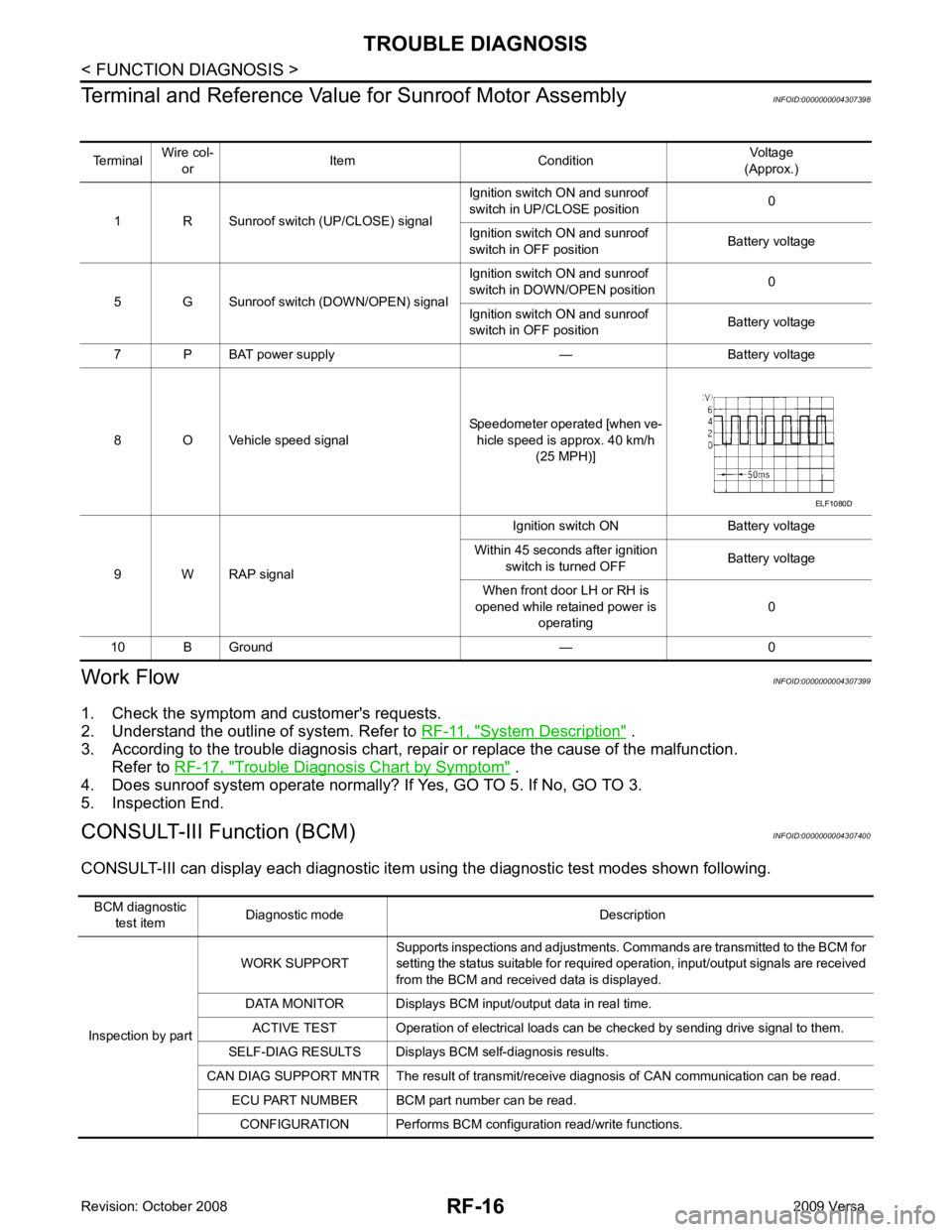
Terminal
Wire col-
or Item Condition
Voltage
(Approx.)
1 R Sunroof switch (UP/CLOSE) signal Ignition switch ON and sunroof
switch in UP/CLOSE position 0
Ignition switch ON and sunroof
switch in OFF position Battery voltage
5 G Sunroof switch (DOWN/OPEN) signal Ignition switch ON and sunroof
switch in DOWN/OPEN position 0
Ignition switch ON and sunroof
switch in OFF position Battery voltage
7 P BAT power supply — Battery voltage
8 O Vehicle speed signal Speedometer operated [when ve-
hicle speed is approx. 40 km/h (25 MPH)]
9 W RAP signal Ignition switch ON Battery voltage
Within 45 seconds after ignition switch is turned OFF Battery voltage
When front door LH or RH is
opened while retained power is
operating 0
10 B Ground — 0
Page 4098 of 4331
RF
N
O P
Work Support
INFOID:0000000004307401
Active Test INFOID:0000000004307402
Data Monitor INFOID:0000000004307403
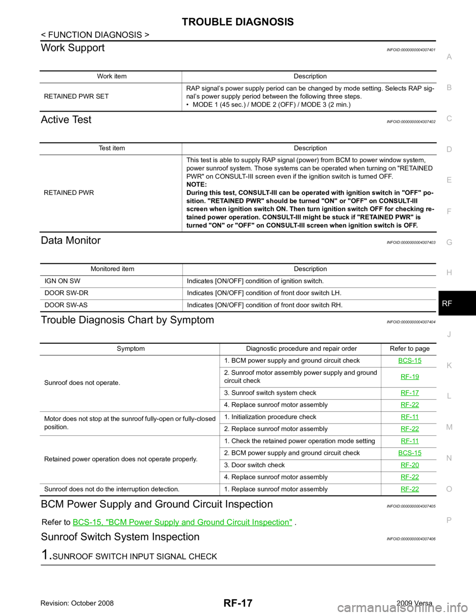
Trouble Diagnosis Chart by Symptom INFOID:0000000004307404
BCM Power Supply and Gr ound Circuit Inspection INFOID:0000000004307405
Refer to BCS-15, " BCM Power Supply and Ground Circuit Inspection " .
Sunroof Switch System Inspection INFOID:0000000004307406Test item Description
RETAINED PWR This test is able to supply RAP signal (power) from BCM to power window system,
power sunroof system. Those systems can be operated when turning on "RETAINED
PWR" on CONSULT-III screen even if the ignition switch is turned OFF.
NOTE:
During this test, CONSULT-III can be operated with ignition switch in "OFF" po-
sition. "RETAINED PWR" should be turned "ON" or "OFF" on CONSULT-III
screen when ignition switch ON. Then turn ignition switch OFF for checking re-
tained power operation. CONSULT-III might be stuck if "RETAINED PWR" is
turned "ON" or "OFF" on CONSULT-III screen when ignition switch is OFF. Symptom Diagnostic procedure and repair order Refer to page
Sunroof does not operate. 1. BCM power supply and ground circuit check
BCS-15 2. Sunroof motor assembly power supply and ground
circuit check RF-19 3. Sunroof switch system check
RF-17 4. Replace sunroof motor assembly
RF-22Motor does not stop at the sunroof fully-open or fully-closed
position. 1. Initialization procedure check
RF-11 2. Replace sunroof motor assembly
RF-22Retained power operation does not operate properly.
1. Check the retained power operation mode setting
RF-11 2. BCM power supply and ground circuit check
BCS-15 3. Door switch check
RF-20 4. Replace sunroof motor assembly
RF-22Sunroof does not do the interruption detection. 1. Replace sunroof motor assembly
RF-22
Page 4101 of 4331
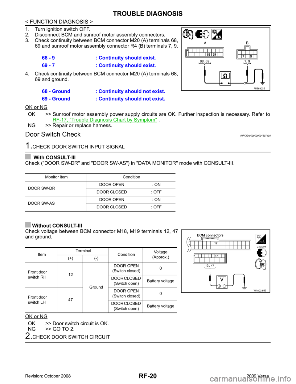
OK >> Sunroof motor assembly power supply circuits
are OK. Further inspection is necessary. Refer to
RF-17, " Trouble Diagnosis Chart by Symptom " .
NG >> Repair or replace harness.
Door Switch Check INFOID:0000000004307408OK >> Door switch circuit is OK.
NG >> GO TO 2. Item
Terminal
ConditionVoltage
(Approx.)
(+) (-)
Front door
switch RH 12
Ground DOOR OPEN
(Switch closed) 0
DOOR CLOSED (Switch open) Battery voltage
Front door
switch LH 47 DOOR OPEN
(Switch closed) 0
DOOR CLOSED (Switch open) Battery voltage