2009 NISSAN TIIDA service indicator
[x] Cancel search: service indicatorPage 3163 of 4331
![NISSAN TIIDA 2009 Service Repair Manual EM-216< SERVICE INFORMATION >
[MR18DE]
CYLINDER BLOCK
Use Undersize Bearing Usage Guide
• When the specified main bearing oil clearance is not obtained with standard size main bearings, use under- s NISSAN TIIDA 2009 Service Repair Manual EM-216< SERVICE INFORMATION >
[MR18DE]
CYLINDER BLOCK
Use Undersize Bearing Usage Guide
• When the specified main bearing oil clearance is not obtained with standard size main bearings, use under- s](/manual-img/5/57398/w960_57398-3162.png)
EM-216< SERVICE INFORMATION >
[MR18DE]
CYLINDER BLOCK
Use Undersize Bearing Usage Guide
• When the specified main bearing oil clearance is not obtained with standard size main bearings, use under- size (US) bearing.
• When using undersize (US) bearing, measure the main bearing inner diameter with bearing installed, and
grind main journal so that the main bearing oil clearance satisfies the standard.
CAUTION:
In grinding crankshaft main jour nal to use undersize bearings,
keep the fillet R [1.5 - 1.7 mm (0.059 - 0.067 in)] (A).
Bearing undersize table Unit: mm (in)
Inspection After Disassembly INFOID:0000000004307161
CRANKSHAFT END PLAY
• Measure the clearance between thrust bearings and crankshaft arm when crankshaft is moved fully forward or backward with a dial
indicator (A).
• If the measured value exceeds the limit, replace thrust bearings, and measure again. If it still exc eeds the limit, replace crankshaft
also.
CONNECTING ROD SIDE CLEARANCE 01
UPR 1.996 - 1.999 (0.0786 - 0.0787) Black
Grade and color are different
between upper and lower bear-
ings.
LWR 1.999 - 2.002 (0.0787 - 0.0788) Brown
12 UPR 1.999 - 2.002 (0.0787 - 0.0788) Brown
LWR 2.002 - 2.005 (0.0788 - 0.0789) Green
23 UPR 2.002 - 2.005 (0.0788- 0.0789) Green
LWR 2.005 - 2.008 (0.0789 - 0.0791) Yellow
34 UPR 2.005 - 2.008 (0.0789 - 0.0791) Yellow
LWR 2.008 - 2.011 (0.0791 - 0.0792) Blue
45 UPR 2.008 - 2.011 (0.0791 - 0.0792) Blue
LWR 2.011 - 2.014 (0.0792 - 0.0793) Pink
56 UPR 2.011 - 2.014 (0.0792 - 0.0793) Pink
LWR 2.014 - 2.017 (0.0793 - 0.0794) Purple
67 UPR 2.014 - 2.017 (0.0793 - 0.0794) Purple
LWR 2.017 - 2.020 (0.0794 - 0.0795) White
Grade number Thickness Identification color Remarks PBIC3263J
Size Thickness
US 0.25 (0.0098) 2.126 - 2.134 (0.0837 - 0.0840) Standard : 0.10 - 0.26 mm (0.0039 - 0.0102 in)
Limit : 0.30 mm (0.012 in) PBIC3252J
Page 3169 of 4331
![NISSAN TIIDA 2009 Service Repair Manual EM-222< SERVICE INFORMATION >
[MR18DE]
CYLINDER BLOCK
• Measure the outer diameter of crankshaft main journals with a
micrometer (A).
• If out of the standard, measure the main b NISSAN TIIDA 2009 Service Repair Manual EM-222< SERVICE INFORMATION >
[MR18DE]
CYLINDER BLOCK
• Measure the outer diameter of crankshaft main journals with a
micrometer (A).
• If out of the standard, measure the main b](/manual-img/5/57398/w960_57398-3168.png)
EM-222< SERVICE INFORMATION >
[MR18DE]
CYLINDER BLOCK
• Measure the outer diameter of crankshaft main journals with a
micrometer (A).
• If out of the standard, measure the main bearing oil clearance. Then use undersize bearing. Follow the "MAIN BEARING OIL
CLEARANCE" procedure.
CRANKSHAFT PIN JOURNAL DIAMETER
• Measure the outer diameter of crankshaft pin journal with a micrometer.
• If out of the standard, measure the connecting rod bear ing oil clearance. Then use undersize bearing. Follow
the "CONNECTING ROD BEARIN G OIL CLEARANCE" procedure.
OUT-OF-ROUND AND TAPER OF CRANKSHAFT
• Measure the dimensions at four different points as shown on each main journal and pin journal with a micrometer.
• Out-of-round is indicated by the difference in dimensions between (X) and (Y) at (A) and (B).
• Taper is indicated by the difference in dimension between (A) and
(B) at (X) and (Y).
• If the measured value exceeds the lim it, correct or replace crankshaft.
• If corrected, measure the bearing oil clearance of t he corrected main journal and/or pin journal. Then select
main bearing and/or connecting rod bearing. Follow the "MAIN BEARING OIL CLEARANCE" and/or "CON-
NECTING ROD BEARING OIL CLEARANCE" procedures.
CRANKSHAFT RUNOUT
• Place a V-block on a precise flat table to support the journals on the both end of the crankshaft.
• Place a dial indicator (A) straight up on the No. 3 journal.
• While rotating crankshaft, read t he movement of the pointer on the
dial indicator. (Total indicator reading)
• If it exceeds the limit, replace crankshaft.
CONNECTING ROD BEARING OIL CLEARANCE
Method by Calculation Standard: 51.959 - 51.979 mm (2.0456 - 2.0464 in) dia. PBIC3457J
Standard: 43.953 - 43.971 mm (1.7304-1.7311 in) dia.
Limit: Out-of-round [Difference between (X) and (Y)] : 0.0035 mm (0.0001 in)
Taper [Difference between (A) and (B)] : 0.0035 mm (0.0001 in) PBIC3459J
Standard : 0.05 mm (0.0020 in)
Limit : 0.10 mm (0.0040 in) PBIC3458J
Page 3179 of 4331
![NISSAN TIIDA 2009 Service Repair Manual EM-232< SERVICE INFORMATION >
[MR18DE]
SERVICE DATA AND SPECIFICATIONS (SDS)
*: Total indicator reading
CYLINDER BLOCK Unit: mm (in)
Camshaft cam height (A)
Intake 44.605 - 44.795 (1.7560 - 1.7635) 44 NISSAN TIIDA 2009 Service Repair Manual EM-232< SERVICE INFORMATION >
[MR18DE]
SERVICE DATA AND SPECIFICATIONS (SDS)
*: Total indicator reading
CYLINDER BLOCK Unit: mm (in)
Camshaft cam height (A)
Intake 44.605 - 44.795 (1.7560 - 1.7635) 44](/manual-img/5/57398/w960_57398-3178.png)
EM-232< SERVICE INFORMATION >
[MR18DE]
SERVICE DATA AND SPECIFICATIONS (SDS)
*: Total indicator reading
CYLINDER BLOCK Unit: mm (in)
Camshaft cam height (A)
Intake 44.605 - 44.795 (1.7560 - 1.7635) 44.405 (1.7482)
Exhaust 43.175 - 43.365 (1.6997 - 1.7072) 42.975 (1.6919)
Camshaft flange 3.877 - 3.925 (0.1526 - 0.1545) —
Camshaft runout [TIR*] Less than 0.02 mm (0.0008) 0.05 (0.0020)
Camshaft sprocket runout [TIR*] — 0.15 (0.0059) SEM671
Top surface distortion Limit 0.1 (0.004)
Cylinder bore Inner diameter Standard Grade No. 1 84.000 - 84.010 (3.3071 - 3.3075)
Grade No. 2 84.010 - 84.020 (3.3075 - 3.3079) PBIC4017E
Page 3241 of 4331
FSU
N
O P
FRONT SUSPENSION ASSEMBLY
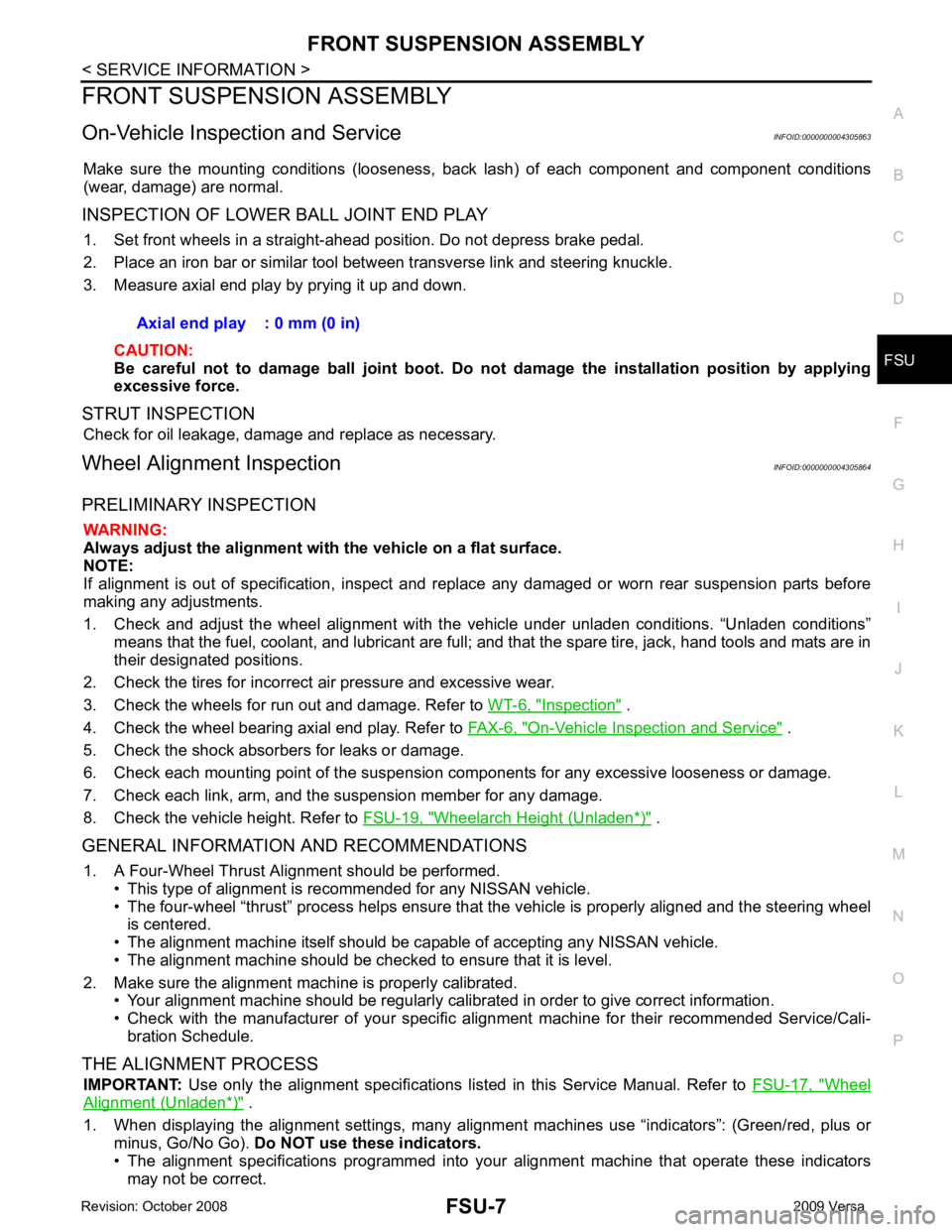
On-Vehicle Inspection and Service INFOID:0000000004305863
Make sure the mounting conditions (looseness, back lash) of each component and component conditions
(wear, damage) are normal.
INSPECTION OF LOWER BALL JOINT END PLAY 1. Set front wheels in a straight-ahead position. Do not depress brake pedal.
2. Place an iron bar or similar tool bet ween transverse link and steering knuckle.
3. Measure axial end play by prying it up and down.
CAUTION:
Be careful not to damage ball joint boot. Do not damage the installation position by applying
excessive force.
STRUT INSPECTION Check for oil leakage, damage and replace as necessary.
Wheel Alignment Inspection INFOID:0000000004305864
PRELIMINARY INSPECTION WARNING:
Always adjust the alignment with the vehicle on a flat surface.
NOTE:
If alignment is out of specification, inspect and r eplace any damaged or worn rear suspension parts before
making any adjustments.
1. Check and adjust the wheel alignment with the vehicle under unladen conditions. “Unladen conditions”
means that the fuel, coolant, and lubricant are full; and that the spare tire, jack, hand tools and mats are in
their designated positions.
2. Check the tires for incorrect air pressure and excessive wear.
3. Check the wheels for run out and damage. Refer to WT-6, " Inspection " .
4. Check the wheel bearing axial end play. Refer to FAX-6, " On-Vehicle Inspection and Service " .
5. Check the shock absorbers for leaks or damage.
6. Check each mounting point of the suspension components for any excessive looseness or damage.
7. Check each link, arm, and the suspension member for any damage.
8. Check the vehicle height. Refer to FSU-19, " Wheelarch Height (Unladen*) " .
GENERAL INFORMATION AND RECOMMENDATIONS 1. A Four-Wheel Thrust Alignment should be performed. • This type of alignment is re commended for any NISSAN vehicle.
• The four-wheel “thrust” process helps ensure that the vehicle is properly aligned and the steering wheel
is centered.
• The alignment machine itself should be ca pable of accepting any NISSAN vehicle.
• The alignment machine should be checked to ensure that it is level.
2. Make sure the alignment machine is properly calibrated. • Your alignment machine should be regularly calib rated in order to give correct information.
• Check with the manufacturer of your specific a lignment machine for their recommended Service/Cali-
bration Schedule.
THE ALIGNMENT PROCESS IMPORTANT: Use only the alignment specifications listed in this Service Manual. Refer to FSU-17, " Wheel
Alignment (Unladen*) " .
1. When displaying the alignment settings, many alignm ent machines use “indicators”: (Green/red, plus or
minus, Go/No Go). Do NOT use these indicators.
• The alignment specifications programmed into your alignment machine that operate these indicators
may not be correct. Axial end play : 0 mm (0 in)
Page 3302 of 4331
GI
N
O P
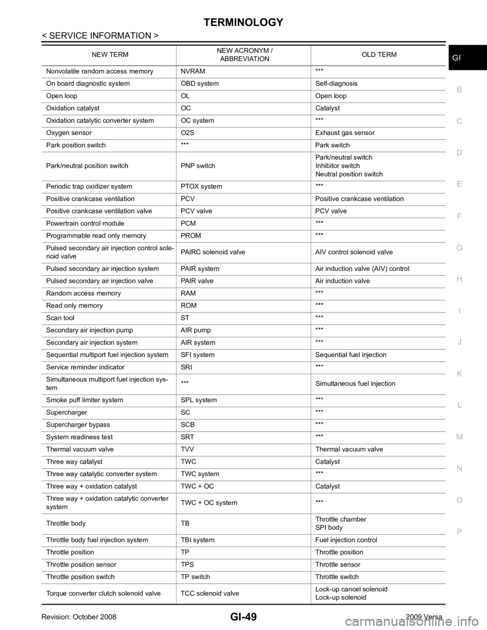
Nonvolatile random access memory NVRAM ***
On board diagnostic system OBD system Self-diagnosis
Open loop OL Open loop
Oxidation catalyst OC Catalyst
Oxidation catalytic converter system OC system ***
Oxygen sensor O2S Exhaust gas sensor
Park position switch *** Park switch
Park/neutral position switch PNP switch Park/neutral switch
Inhibitor switch
Neutral position switch
Periodic trap oxidizer system PTOX system ***
Positive crankcase ventilation PCV Positive crankcase ventilation
Positive crankcase ventilation valve PCV valve PCV valve
Powertrain cont rol module PCM ***
Programmable read only memory PROM ***
Pulsed secondary air injection control sole-
noid valve PAIRC solenoid valve AIV control solenoid valve
Pulsed secondary air injection system PAIR system Air induction valve (AIV) control
Pulsed secondary air injection valve PAIR valve Air induction valve
Random access memory RAM ***
Read only memory ROM ***
Scan tool ST ***
Secondary air injection pump AIR pump ***
Secondary air injection system AIR system ***
Sequential multiport fuel injection system SFI system Sequential fuel injection
Service reminder indicator SRI ***
Simultaneous multiport fuel injection sys-
tem *** Simultaneous fuel injection
Smoke puff limiter system SPL system ***
Supercharger SC ***
Supercharger bypass SCB ***
System readiness test SRT ***
Thermal vacuum valve TVV Thermal vacuum valve
Three way catalyst TWC Catalyst
Three way catalytic converter system TWC system ***
Three way + oxidation catalyst TWC + OC Catalyst
Three way + oxidation catalytic converter
system TWC + OC system ***
Throttle body TB Throttle chamber
SPI body
Throttle body fuel injection system TBI system Fuel injection control
Throttle position TP Throttle position
Throttle position sensor TPS Throttle sensor
Throttle position switch TP switch Throttle switch
Torque converter clutch solenoid valve TCC solenoid valve Lock-up cancel solenoid
Lock-up solenoid
NEW TERM
NEW ACRONYM /
ABBREVIATION OLD TERM
Page 3607 of 4331
LT
N
O P
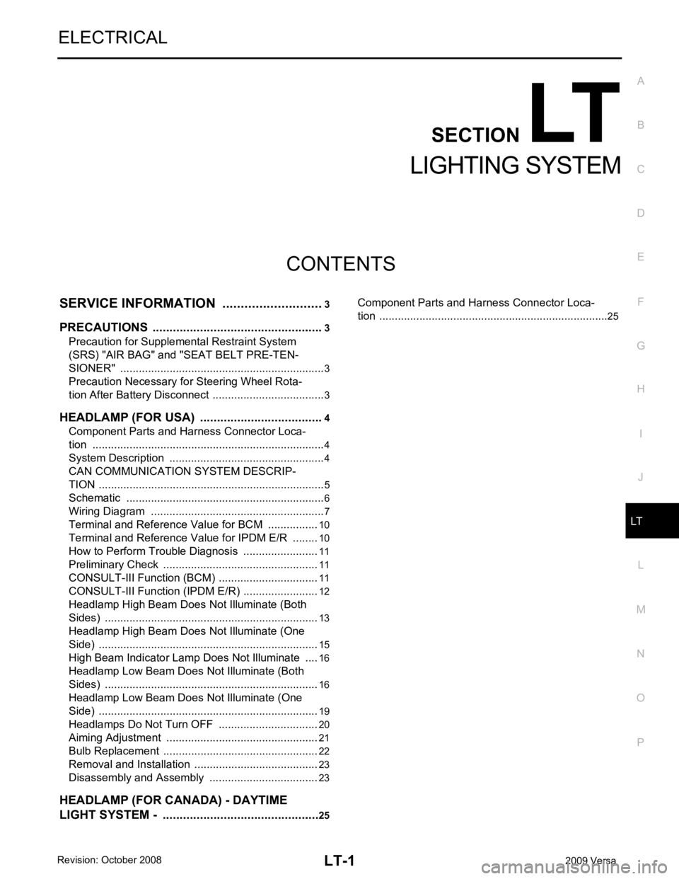
CONTENTS
LIGHTING SYSTEM
SERVICE INFORMATION .. ..........................3
PRECAUTIONS .............................................. .....3
Precaution for Supplemental Restraint System
(SRS) "AIR BAG" and "SEAT BELT PRE-TEN-
SIONER" ............................................................. ......
3
Precaution Necessary fo r Steering Wheel Rota-
tion After Battery Disconnect ............................... ......
3
HEADLAMP (FOR USA) ................................ .....4
Component Parts and Harness Connector Loca-
tion ...................................................................... ......
4
System Description ............................................. ......4
CAN COMMUNICATION SYSTEM DESCRIP-
TION .................................................................... ......
5
Schematic ........................................................... ......6
Wiring Diagram ................................................... ......7
Terminal and Reference Value for BCM ............. ....10
Terminal and Reference Value for IPDM E/R ..... ....10
How to Perform Trouble Diagnosis ..................... ....11
Preliminary Check ............................................... ....11
CONSULT-III Function (BCM) ............................. ....11
CONSULT-III Function (IPDM E/R) ..................... ....12
Headlamp High Beam Does Not Illuminate (Both
Sides) .................................................................. ....
13
Headlamp High Beam Does Not Illuminate (One
Side) .................................................................... ....
15
High Beam Indicator Lamp Does Not Illuminate .....16
Headlamp Low Beam Does Not Illuminate (Both
Sides) .................................................................. ....
16
Headlamp Low Beam Does Not Illuminate (One
Side) .................................................................... ....
19
Headlamps Do Not Turn OFF ............................. ....20
Aiming Adjustment .............................................. ....21
Bulb Replacement ........ ...........................................22
Removal and Installation .........................................23
Disassembly and Assembly ................................ ....23
HEADLAMP (FOR CANADA) - DAYTIME
LIGHT SYSTEM - ........................................... ....25 Component Parts and Harness Connector Loca-
tion ....................................................................... ....
25
Page 3622 of 4331
LT-16< SERVICE INFORMATION >
HEADLAMP (FOR USA)
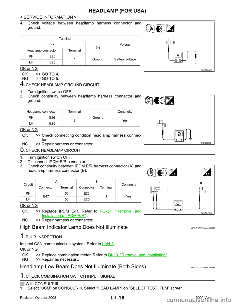
4. Check voltage between headlamp harness connector and ground.
OK or NG OK >> GO TO 4.
NG >> GO TO 5. 4.
CHECK HEADLAMP GROUND CIRCUIT
1. Turn ignition switch OFF.
2. Check continuity between headlamp harness connector and ground.
OK or NG OK >> Check connecting condition headlamp harness connec-
tor.
NG >> Repair harness or connector. 5.
CHECK HEADLAMP CIRCUIT
1. Turn ignition switch OFF.
2. Disconnect IPDM E/R connector.
3. Check continuity between IPDM E/R harness connector (A) and
headlamp harness connector (B).
OK or NG OK >> Replace IPDM E/R. Refer to
PG-27, " Removal and
Installation of IPDM E/R " .
NG >> Repair harness or connector.
High Beam Indicator Lam p Does Not Illuminate INFOID:00000000043065331.
BULB INSPECTION
Inspect CAN communication system. Refer to LAN-8 .
OK or NG OK >> Replace combination meter. Refer to
DI-19, " Removal and Installation " .
NG >> Repair as necessary.
Headlamp Low Beam Does Not Illuminate (Both Sides) INFOID:00000000043065341.
CHECK COMBINATION SWITCH INPUT SIGNAL
With CONSULT-III
1. Select “BCM” on CONSULT-III. Select “HEAD LAMP” on “SELECT TEST ITEM” screen.
Terminal
Voltage
(+)
(− )
Headlamp connector Terminal
RH E26 1 Ground Battery voltage
LH E25 WKIA5552E
Headlamp connector Terminal
Ground Continuity
RH E26 2 Yes
LH E25 PKIC0961E
Circuit
A B
Continuity
Connector Terminal Connector Terminal
RH E47 56 E26
1 Yes
LH 55 E25 WKIA5470E
Page 3769 of 4331
MA-26< SERVICE INFORMATION >
ENGINE MAINTENANCE (MR18DE)
ENGINE MAINTENANCE (MR18DE)
DRIVE BELT
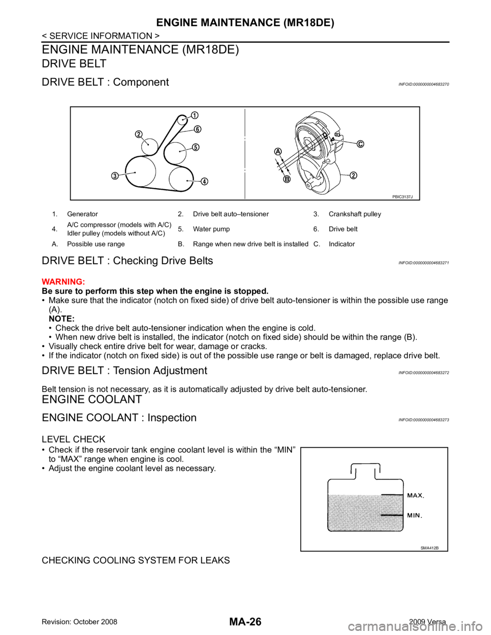
DRIVE BELT : Component INFOID:0000000004683270
DRIVE BELT : Checking Drive Belts INFOID:0000000004683271
WARNING:
Be sure to perform this step when the engine is stopped.
• Make sure that the indicator (notch on fixed side) of drive belt auto-tensioner is within the possible use range
(A).
NOTE:
• Check the drive belt auto-tensioner indication when the engine is cold.
• When new drive belt is installed, the indicator (notch on fixed side) should be within the range (B).
• Visually check entire drive belt for wear, damage or cracks.
• If the indicator (notch on fixed side) is out of t he possible use range or belt is damaged, replace drive belt.
DRIVE BELT : Tension Adjustment INFOID:0000000004683272
Belt tension is not necessary, as it is autom atically adjusted by drive belt auto-tensioner.
ENGINE COOLANT
ENGINE COOLANT : Inspection INFOID:0000000004683273
LEVEL CHECK
• Check if the reservoir tank engine coolant level is within the “MIN” to “MAX” range when engine is cool.
• Adjust the engine coolant level as necessary.
CHECKING COOLING SYSTEM FOR LEAKS 1. Generator 2. Drive belt auto–tensioner 3. Crankshaft pulley
4. A/C compressor (models with A/C)
Idler pulley (models without A/C) 5. Water pump 6. Drive belt
A. Possible use range B. Range when new drive belt is installed C. Indicator PBIC3137J
SMA412B