2009 NISSAN QASHQAI lock
[x] Cancel search: lockPage 198 of 297
Downloaded from www.Manualslib.com manuals search engine When parked on a sloping driveway, turn the
wheels so the vehicle will not roll into the street
in case it moves.
FACING DOWNHILL:j1
Turn the wheels into the kerb, allow the vehicle
to move forward until the kerb side wheel gently
touches the kerb. Then set the handbrake.
FACING UPHILL:j2
Turn the wheels away from the kerb and allow
the vehicle to move back until the kerb side wheel
gently touches the kerb. Then set the handbrake.
NO KERB — FACING DOWNHILL OR UPHILL:j3
Turn the wheels toward the side of the road so
the vehicle will move away from the centre of the
road if it moves. Then set the handbrake.
Turn the ignition switch to the LOCK position
and remove the key/Intelligent Key (where fit-
ted).
Always turn off ignition after parking a vehicle
with Stop/Start System fitted to avoid a possible
flat battery.
NOTE
The Stop/Start System is designed to prevent
unnecessary fuel consumption, exhaust emis-
sions and noise during a journey. The Stop/
Start System does not automatically turn off
ignition at the end of a journey. Your new vehicle was designed to be used primarily
to carry passengers and luggage.
Remember that towing a trailer will place additional
loads on your vehicle’s engine, drive-train, steering,
braking and other systems. Towing a trailer will also
exaggerate other conditions, such as sway caused
by crosswinds, rough road surfaces or passing
trucks. Driving style and speed must be adjusted
according to the circumstances. Before towing a
trailer, see a NISSAN dealer or qualified workshop
for an explanation of towing equipment and its
proper use.
OPERATING PRECAUTIONS
Avoid towing a trailer during the running-in
schedule.
Choose proper coupling devices (trailer hitch,
safety chain, roof carrier, etc.) for your vehicle
and trailer. These devices are available from a
NISSAN dealer or qualified workshop where you
can also obtain more detailed information about
trailer towing.
Heavy-duty kits are available at a NISSAN dealer
or qualified workshop.
It is advisable to contact a NISSAN dealer or
qualified workshop for towing details, before
towing a trailer up steep slopes for long dis-
tances.
Never allow the total trailer load (trailer weight
plus its cargo weight) to exceed the maximum
set for the coupling device. Contact a NISSAN dealer or qualified workshop
for more information on this matter.
The trailer must be loaded so that heavy goods
are distributed over the axle and as low in the
trailer as possible. Poor load distribution can se-
riously affect the stability of the trailer and tow
vehicle.
Do not exceed the maximum permitted vertical
load on the trailer hitch.
Before driving, make sure that the lighting sys-
tem of the trailer works properly.
When towing with 4WD models, the 4WD mode
switch should be in the AUTO position. Using
the vehicle in AUTO mode gives better traction,
particularly when moving off from stationary and/
or on an incline, as the vehicle is less likely to
wheel spin.
Avoid abrupt starts, accelerations and stops.
Avoid sharp turns and lane changes.
Always drive your vehicle at a moderate speed.
Always block the wheels on both vehicle and
trailer when parking. Apply the handbrake (where
fitted) on the trailer. Parking on a steep slope is
not recommended.
If parking on a steep slope is unavoidable it is
also advisable to put the vehicle into gear, or
select P (Park (AT or CVT models), and turn the
front wheels into the kerb (in addition to the other
precautions described). Before parking on a
TRAILER TOWING
Starting and driving5-35
Page 201 of 297
Downloaded from www.Manualslib.com manuals search engine When leaving your vehicle unoccupied:
Always remove the ignition key or Intelligent Key
(where fitted) and take it with you – even in your
own garage.
Close all windows completely and lock all doors.
Always park your vehicle where it can be seen.
At night, park in a well lit area.
If the vehicle is equipped with an alarm or immo-
bilization device, use it – even for short periods.
Do not leave children and pets in the vehicle
unattended.
Do not leave valuables on view to tempt a thief.
Always take your valuables with you. If you must
leave something in your vehicle, lock it in the lug-
gage compartment or hide it out of sight.
Do not leave the vehicle documents in your ve-
hicle. In the unfortunate event of your vehicle
being stolen, the documents will only help a thief
to sell the vehicle.
Do not leave articles on a roof rack as they are
particularly vulnerable. If possible, remove them
from the rack and lock them inside the vehicle.
Do not leave the spare key or Intelligent Key in
the vehicle – keep it in a safe place at home.
Do not leave a note of your vehicle’s key number
in the vehicle. A thief may break into the vehicle,
note the key number and return with a new key
and drive the vehicle.
WARNING
If the Electrically Power Assisted Steering
warning light (EPAS) illuminates while driv-
ing, the power assist for steering will be dis-
abled. Greater steering efforts are required to
operate the steering wheel, especially in
sharp turns and at low speed. Stop the ve-
hicle as soon as safely possible and contact a
NISSAN dealer or qualified workshop for fur-
ther assistance.
In certain circumstances, factors external to
the EPAS system may contribute to the illumi-
nation of the warning light. If the warning light
illuminates, stop the vehicle as soon as safely
possible if driving. Turn the ignition switch to
the “OFF” position and wait for approximately
20 seconds, then turn the ignition switch to
the ON position again. If the light remains illu-
minated, we recommend you to contact a
NISSAN dealer or qualified workshop. See
“Warning/indicator lights and audible
reminders” in the “2. Instruments and
controls” section for further details regarding
the EPAS warning light.
The EPAS (Electrically Power Assisted Steering)
system is designed to assist steering.
The steering may appear to feel slightly stiff follow-
ing parking manoeuvres including a great deal of
steering. This is not a malfunction; it is caused by a
control system designed to prevent the motor from overheating. No servicing is required. The EPAS
system will return to normal operation the next time
the vehicle is driven.
Similarly, the EPAS system may not provide full as-
sistance during periods of reduced battery voltage
but will recover once normal battery voltage is re-
stored.
If the EPAS warning light comes on while the engine
is running, it may indicate that the EPAS system is
not working properly. As result greater steering ef-
forts are required to steer the steering wheel, espe-
cially in sharp turns and at low speeds. Have the
system checked by a NISSAN dealer or qualified
workshop as soon as possible.
NOTE
Incorrectly inflated tyres can lead to poor steer-
ing ability and make the driver suspect a steering
problem: keep the vehicle’s tyres inflated to the
correct pressure at all times.
CAUTION
Any malfunction or accident that could have dam-
aged the steering components (including actual
or attempted theft damage) should be reported
to a NISSAN dealer or qualified workshop.
VEHICLE SECURITY
POWER STEERING SYSTEM
5-38Starting and driving
Page 202 of 297

Downloaded from www.Manualslib.com manuals search engine The brake system has two separate hydraulic cir-
cuits. If one circuit malfunctions, you will still have
braking ability with two wheels.
BRAKE PRECAUTIONS
Vacuum assisted brake
The brake booster aids braking by using engine
vacuum. If the engine stops or the drive belt is bro-
ken, you can stop the vehicle by depressing the
brake pedal. However, greater foot pressure on the
brake pedal will be required to stop the vehicle and
the stopping distance will be longer.
Wet brakes
When the vehicle is washed or driven through wa-
ter, the brakes may get wet. As a result, your brak-
ing distance will be longer and the vehicle may pull
to one side during braking.
To dry brakes, drive the vehicle at a safe speed
while lightly pressing the brake pedal to heat up the
brakes. Do this until the brakes return to normal.
Avoid driving the vehicle at high speeds until the
brakes function correctly.
Using the brakes
Avoid resting your foot on the brake pedal while
driving. This will overheat the brakes, wear out the
brake linings and pads faster and reduce fuel
economy performance.
To help reduce brake wear and to prevent the brakes
from overheating, reduce speed and downshift to a
lower gear before going down a slope or long down-hill gradient. Overheated brakes may reduce brak-
ing performance and could result in loss of vehicle
control.
CAUTION
While driving on a slippery surface, be careful
when braking, accelerating or downshifting.
Abrupt braking actions or sudden acceleration
could cause the wheels to skid and result in an
accident.
Be aware that brakes will fade if repeated heavy
brake applications are made.
Driving uphill
When starting on a steep gradient, it is sometimes
difficult to operate the brake (AT or CVT models) or
both the brake and clutch (MT models). Use the
handbrake to hold the vehicle. Do not slip the clutch
(MT models). When ready to start, slowly release
the handbrake while depressing the accelerator
pedal and releasing the clutch (MT models) or de-
pressing the accelerator pedal (AT or CVT models).
Driving downhill
The engine braking action is effective for controlling
the vehicle while descending hills.
The gear lever (MT models) should be placed in a
gear position low enough to obtain sufficient engine
braking.
For the AT or CVT models, a low gear position in
the manual shift mode, low enough to obtain suffi-
cient engine braking, should be selected.
ANTI-LOCK BRAKING SYSTEM (ABS)
WARNING
The Anti-lock Braking System (ABS) is a so-
phisticated device, but it cannot prevent acci-
dents resulting from careless or dangerous
driving techniques. It can help maintain ve-
hicle control during braking on slippery sur-
faces. Remember that stopping distances
may also be longer on rough, gravel or snow
covered roads, or if you are using snow
chains. Always maintain a safe distance from
the vehicle in front of you. Ultimately, the
driver is responsible for safety.
Tyre type and condition may also affect brak-
ing effectiveness.
– When replacing tyres, install the specified
size of tyres on all four wheels.
– When installing a spare tyre, make sure it is the proper size and type as specified on
the tyre placard. See “Vehicle
identification” in the “9. Technical
information” section for the tyre placard
location.
– For detailed information, see “Wheels and tyres” in the “8. Maintenance and
do-it-yourself” section.
The Anti-lock Braking System (ABS) controls the
brakes so that the wheels do not lock during hard
braking or when braking on slippery surfaces. The
system detects the rotation speed at each wheel
BRAKE SYSTEM
Starting and driving5-39
Page 203 of 297

Downloaded from www.Manualslib.com manuals search engine and varies the brake fluid pressure to prevent each
wheel from locking and sliding. By preventing each
wheel from locking, the system helps the driver to
maintain steering control and helps to minimise
swerving and spinning on slippery surfaces.
Using the system
Depress the brake pedal and hold it down. Depress
the brake pedal with firm steady pressure, but do
not pump the brakes. The ABS will operate to pre-
vent the wheels from locking up. Steer the vehicle to
avoid obstacles.
WARNING
Do not pump the brake pedal. Doing so may in-
crease the stopping distance.
Self-test feature
The ABS includes electronic sensors, electric
pumps, hydraulic solenoids and a computer. The
computer has a built-in diagnostic feature that tests
the system each time you start the engine and move
thevehicleatalowspeedinforwardorreverse.
When the self-test occurs, you may hear a “clunk”
noise and/or feel a pulsation in the brake pedal. This
is normal and does not indicate a malfunction. If the
computer senses a malfunction, it switches the ABS
off and illuminates the ABS warning light on the
instrument panel. The brake system then operates
normally, but without anti-lock assistance.
If the ABS warning light illuminates during the self-
test or while driving, have the vehicle checked by a
NISSAN dealer or qualified workshop.
Normal operation
The ABS will not initiate at speeds below 5 to 10
km/h (3 to 6 MPH). The speeds will vary according
to road conditions.
When the ABS senses that one or more wheels are
close to locking up, the actuator rapidly applies and
releases hydraulic pressure. This action is similar to
pumping the brakes very quickly. You may feel a
pulsation in the brake pedal and hear a noise from
the actuator under the bonnet when it is operating.
This is normal and indicates that the ABS is working
properly. However, the pulsation may indicate that
road conditions are hazardous and extra care is re-
quired while driving. When accelerating, driving on slippery surfaces or
suddenly avoiding obstacles on roads, the vehicle
might swerve or slip. The Electronic Stability Pro-
gramme (ESP) system continuously monitors and
compares the driver’s intended speed and the travel
direction. The system adjusts wheel brake pressure
and engine torque to assist in improving vehicle sta-
bility.
When the ESP system is operating, the “SLIP”
indicator light () in the combination meter
blinks.
When only the traction control (TCS) system in
the ESP system is operating, the “SLIP” indica-
tor light (
) in the combination meter will also
blink.
If the “SLIP” indicator light () blinks, the
road conditions are slippery. Be sure to drive
carefully. See “Warning/indicator lights and au-
dible reminders” in the “2. Instruments and
controls” section.
Indicator light
If a malfunction occurs in the system, the “SLIP”
indicator light (
) and the ESP indicator light
() come on in the combination meter.
As long as these indicator lights are on, the trac-
tion control function is cancelled.
The ESP system uses Active Brake Limited Slip
(ABLS) system to improve vehicle traction. The Ac-
tive Brake Limited Slip (ABLS) system works when
one of the driving wheels is spinning on a slippery
ELECTRONIC STABILITY
PROGRAMME (ESP) SYSTEM
(where fitted)
5-40Starting and driving
Page 210 of 297
Downloaded from www.Manualslib.com manuals search engine 6. Turn off the engine.
7. Open the bonnet (for details, see “Bonnetrelease” in the “3. Pre-driving checks and
adjustments” section) in order to:
Warn other traffic.
Signal to professional road assistance that
you require assistance.
8. Have all passengers exit the vehicle and stand in a safe place, away from traffic and clear of the
vehicle.
CHANGING FLAT TYRE (Models with
spare wheel, where fitted)
Blocking the wheels
WARNING
Make sure to block the appropriate wheel to pre-
vent the vehicle from moving, which may cause
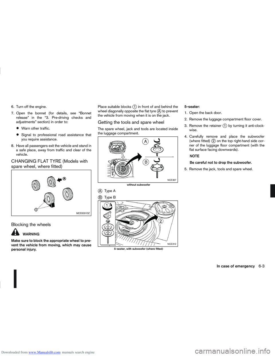
personal injury. Place suitable blocks
j1 in front of and behind the
wheel diagonally opposite the flat tyrejA to prevent
the vehicle from moving when it is on the jack.
Getting the tools and spare wheel
The spare wheel, jack and tools are located inside
the luggage compartment.
jA Type A
jB Type B 5–seater:
1. Open the back door.
2. Remove the luggage compartment floor cover.
3. Remove the retainer
j1 by turning it anti-clock-
wise.
4. Carefully remove and place the subwoofer (where fitted)
j2 on the top right-hand side cor-
ner of the luggage floor compartment (with the
flat surface facing downwards).
NOTE
Be careful not to drop the subwoofer.
5. Remove the jack, tools and spare wheel.
MCE0001DZ
NCE307
without subwoofer
NCE312
5–seater, with subwoofer (where fitted)
In case of emergency6-3
Page 211 of 297
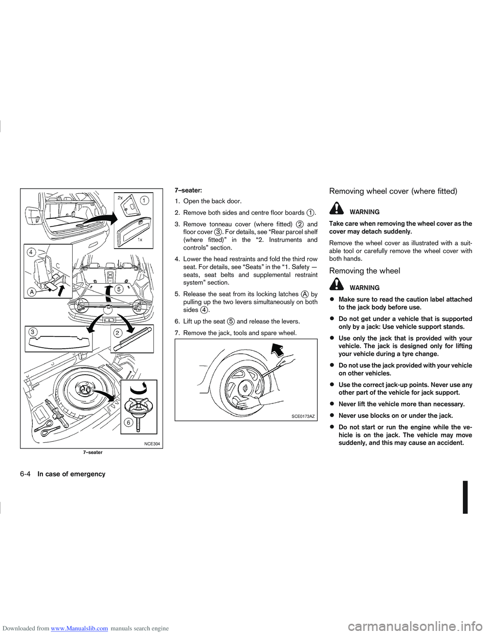
Downloaded from www.Manualslib.com manuals search engine 7–seater:
1. Open the back door.
2. Remove both sides and centre floor boards
j1.
3. Remove tonneau cover (where fitted)
j2 and
floor coverj3 . For details, see “Rear parcel shelf
(where fitted)” in the “2. Instruments and
controls” section.
4. Lower the head restraints and fold the third row seat. For details, see “Seats” in the “1. Safety —
seats, seat belts and supplemental restraint
system” section.
5. Release the seat from its locking latches
jAby
pulling up the two levers simultaneously on both
sides
j4.
6. Lift up the seat
j5 and release the levers.
7. Remove the jack, tools and spare wheel.
Removing wheel cover (where fitted)
WARNING
Take care when removing the wheel cover as the
cover may detach suddenly.
Remove the wheel cover as illustrated with a suit-
able tool or carefully remove the wheel cover with
both hands.
Removing the wheel
WARNING
Make sure to read the caution label attached
to the jack body before use.
Do not get under a vehicle that is supported
only by a jack: Use vehicle support stands.
Use only the jack that is provided with your
vehicle. The jack is designed only for lifting
your vehicle during a tyre change.
Do not use the jack provided with your vehicle
on other vehicles.
Use the correct jack-up points. Never use any
other part of the vehicle for jack support.
Never lift the vehicle more than necessary.
Never use blocks on or under the jack.
Do not start or run the engine while the ve-
hicle is on the jack. The vehicle may move
suddenly, and this may cause an accident.
NCE304
7–seater
SCE0173AZ
6-4In case of emergency
Page 212 of 297
Downloaded from www.Manualslib.com manuals search engine Never allow passengers to stay in the vehicle
while it is on the jack.
Remove all loads before lifting the vehicle with
the jack.
Make sure to block the wheel diagonally op-
posite the flat tyre as described earlier in this
section.
CAUTION
The jack should be used on firm, level ground.
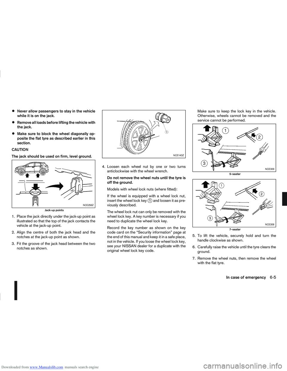
1. Place the jack directly under the jack-up point as illustrated so that the top of the jack contacts the
vehicle at the jack-up point.
2. Align the centre of both the jack head and the notches at the jack-up point as shown.
3. Fit the groove of the jack head between the two notches as shown. 4. Loosen each wheel nut by one or two turns
anticlockwise with the wheel wrench.
Do not remove the wheel nuts until the tyre is
off the ground.
Models with wheel lock nuts (where fitted):
If the wheel is equipped with a wheel lock nut,
insert the wheel lock key
j1 and loosen it as pre-
viously described.
The wheel lock nut can only be removed with the
wheel lock key. A key number is necessary if you
need to duplicate the wheel lock key.
Record the key number as shown on the key
code card on the “Security information” page at
the end of this manual and keep it in a safe place,
not in the vehicle. If you loose the wheel lock key,
see your NISSAN dealer for a duplicate with the
original wheel lock key code. Make sure to keep the lock key in the vehicle.
Otherwise, wheels cannot be removed and the
service cannot be performed.
5. To lift the vehicle, securely hold and turn the handle clockwise as shown.
6. Carefully raise the vehicle until the tyre clears the ground.
7. Remove the wheel nuts, then remove the wheel with the flat tyre.NCE256Z
Jack-up points
NCE143Z
NCE309
5–seater
NCE308
7–seater
In case of emergency6-5
Page 213 of 297
Downloaded from www.Manualslib.com manuals search engine CAUTION
The wheel is heavy. Be sure that your feet are
clear of the wheel and use gloves as necessary
to avoid injury.
Installing the wheel
WARNING
The temporary use spare tyre is designed for
emergency use. See “Spare tyre” earlier in
this section.
Never use wheel nuts other than those pro-
vided with your vehicle. Incorrect wheel nuts
or improperly tightened wheel nuts may cause
the wheel to become loose or come off. This
could cause an accident.
Never use oil or grease on the wheel studs or
nuts. This may cause the wheel nuts to be-
come loose.
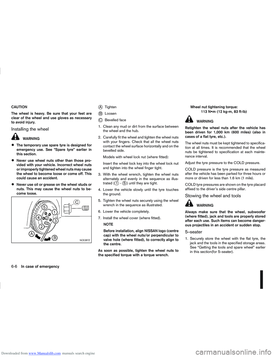
jATighten
jB Loosen
jC Bevelled face
1. Clean any mud or dirt from the surface between the wheel and the hub.
2. Carefully fit the wheel and tighten the wheel nuts with your fingers. Check that all the wheel nuts
contact the wheel surface horizontally and on the
bevelled side.
Models with wheel lock nut (where fitted):
Insert the wheel lock key into the wheel lock nut
and tighten into the wheel finger tight.
3. With the wheel wrench, tighten the wheel nuts alternately and evenly in the sequence as illus-
trated (
j1-j5 ) until they are tight.
4. Lower the vehicle slowly until the tyre touches the ground.
5. Tighten the wheel nuts securely using the wheel wrench in the sequence as illustrated.
6. Lower the vehicle completely.
7. Install the wheel cover (where fitted). NOTE
Before installation, align NISSAN logo (centre
cap) with the wheel nuts/or perpendicular to
valve hole (where fitted), to correctly align to
the centre.
As soon as possible, tighten the wheel nuts to
the specified torque with a torque wrench. Wheel nut tightening torque:
113 (12 kg-m, 83 ft-lb)
WARNING
Retighten the wheel nuts after the vehicle has
been driven for 1,000 km (600 miles) (also in
cases of a flat tyre, etc.).
The wheel nuts must be kept tightened to specifica-
tion at all times. It is recommended that the wheel
nuts be tightened to specification at each mainte-
nance interval.
Adjust the tyre pressure to the COLD pressure.
COLD pressure is the tyre pressure as measured
after the vehicle has been parked for three hours or
more or driven for less than 1.6 km (1 mile).
COLD tyre pressures are shown on the tyre placard
affixed to the driver’s side centre pillar.
Stowing the wheel and tools
WARNING
Always make sure that the wheel, subwoofer
(where fitted), jack and tools are properly stored
after each use. Such items can become danger-
ous projectiles in an accident or sudden stop.
5–seater
1. Securely store the wheel with the flat tyre, the jack and the tools in the specified storage areas.
See “Getting the tools and spare wheel” earlier
in this section(for 5–seater).NCE287Z
6-6In case of emergency