2009 NISSAN MURANO seat adjustment
[x] Cancel search: seat adjustmentPage 31 of 443
Black plate (29,1)
Model "Z51-D" EDITED: 2007/ 10/ 2
SSS0351A
Shoulder belt height adjustment
The shoulder belt anchor height should be
adjusted to the position best for you. (See
“PRECAUTIONS ON SEAT BELT USAGE”
earlier in this section.)
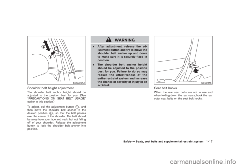
To adjust, pull the adjustment button
*1, and
then move the shoulder belt anchor to the
desired position
*2, so that the belt passes
over the center of the shoulder. The belt should
be away from your face and neck, but not falling
off of your shoulder. Release the adjustment
button to lock the shoulder belt anchor into
position.
WARNING
.After adjustment, release the ad-
justment button and try to move the
shoulder belt anchor up and down
to make sure it is securely fixed in
position.
.The shoulder belt anchor height
should be adjusted to the position
best for you. Failure to do so may
reduce the effectiveness of the
entire restraint system and increase
the chance or severity of injury in an
accident.
SSS0845
Seat belt hooks
When the rear seat belts are not in use and
when folding down the rear seats, hook the rear
outer seat belts on the seat belt hooks.
Safety — Seats, seat belts and supplemental restraint system1-17
Page 37 of 443
Black plate (35,1)
Model "Z51-D" EDITED: 2007/ 10/ 2
loads imposed by correctly fitted
child restraints. Under no circum-
stances are they to be used for adult
seat belts or harnesses.
.Adjustable seatbacks should be
positioned to fit the child restraint,
but as upright as possible.
.After attaching the child restraint,
test it before you place the child in
it. Push it from side to side while
holding the seat near the LATCH
attachment or by the seat belt path.
Try to tug it forward and check to
see if the belt holds the restraint in
place. The child restraint should not
move more than 1 in (25 mm) . If the
restraint is not secure, tighten the
belt as necessary, or put the re-
straint in another seat and test it
again. You may need to try a differ-
ent child restraint. Not all child
restraints fit in all types of vehicles.
.When your child restraint is not in
use, keep it secured with the LATCH
System or a seat belt to prevent it
from being thrown around in case of
a sudden stop or accident.CAUTION
Remember that a child restraint left in a
closed vehicle can become very hot.
Check the seating surface and buckles
before placing your child in the child
restraint.
This vehicle is equipped with a universal child
restraint lower anchor system, referred to as the
Lower Anchors and Tethers for CHildren System
or LATCH. Some child restraints include two
rigid or webbing-mounted attachments that can
be connected to these lower anchors. For
details, see “Lower Anchors and Tethers for
CHildren SYSTEM (LATCH)” later in this sec-
tion.
If you do not have a LATCH compatible child
restraint, the vehicle seat belts can be used.
(See “CHILD RESTRAINT INSTALLATION
USING THE SEAT BELTS” later in this section.)
In general, child restraints are also designed to
be installed with the lap portion of a lap/shoulder
seat belt.
Several manufacturers offer child restraints for
infants and small children of various sizes. When
selecting any child restraint, keep the following
points in mind:
.Choose only a restraint with a label certifying
that it complies with Federal Motor VehicleSafety Standard 213 or Canadian Motor
Vehicle Safety Standard 213.
.Check the child restraint in your vehicle to
be sure it is compatible with the vehicle’s
seat and seat belt system.
.If the child restraint is compatible with your
vehicle, place your child in the child restraint
and check the various adjustments to be
sure the child restraint is compatible with
your child. Choose a child restraint that is
designed for your child’s height and weight.
Always follow all recommended procedures.
All U.S. states and Canadian provinces or
territories require that infants and small
children be restrained in an approved child
restraint at all times while the vehicle is
being operated.
Lower Anchors and Tethers for CHildren
SYSTEM (LATCH)
Your vehicle is equipped with special anchor
points that are used with Lower Anchors and
Tethers for CHildren System (LATCH) compa-
tible child restraints. This system may also be
referred to as the ISOFIX or ISOFIX compatible
system. With this system, you do not have to use
a vehicle seat belt to secure the child restraint.
The LATCH anchor points are provided to install
child restraints in the rear outboard seating
Safety — Seats, seat belts and supplemental restraint system1-23
Page 53 of 443
Black plate (51,1)
Model "Z51-D" EDITED: 2007/ 10/ 2
LRS0464
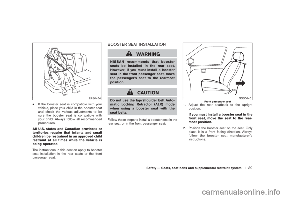
.If the booster seat is compatible with your
vehicle, place your child in the booster seat
and check the various adjustments to be
sure the booster seat is compatible with
your child. Always follow all recommended
procedures.
All U.S. states and Canadian provinces or
territories require that infants and small
children be restrained in an approved child
restraint at all times while the vehicle is
being operated.
The instructions in this section apply to booster
seat installation in the rear seats or the front
passenger seat.
BOOSTER SEAT INSTALLATION
WARNING
NISSAN recommends that booster
seats be installed in the rear seat.
However, if you must install a booster
seat in the front passenger seat, move
the passenger’s seat to the rearmost
position.
CAUTION
Do not use the lap/shoulder belt Auto-
matic Locking Retractor (ALR) mode
when using a booster seat with the
seat belts.
Follow these steps to install a booster seat in the
rear seat or in the front passenger seat:SSS0640Front passenger seat1. Adjust the rear seatback to the upright
position.
If you must install a booster seat in the
front seat, move the seat to the rear-
most position.
2. Position the booster seat on the seat. Only
place it in a front facing direction. Always
follow the booster seat manufacturer’s
instructions.
Safety — Seats, seat belts and supplemental restraint system1-39
Page 87 of 443
Black plate (85,1)
Model "Z51-D" EDITED: 2007/ 10/ 2
AUDIBLE REMINDERS
Key reminder chime
A chime will sound if the driver side door is
opened while the ignition switch is pushed to
the ACC position or pushed to the OFF or
LOCK position with the key left in the key port.
Make sure the ignition switch is pushed to the
OFF position, and take the Intelligent Key with
you when leaving the vehicle.
Light reminder chime
A chime will sound when the driver side door is
opened with the light switch in theorposition and the ignition switch in the ACC
or OFF position.
Turn the light switch off when you leave the
vehicle.
Parking brake reminder chime
The chime will sound if the vehicle is driven with
the parking brake applied. Stop the vehicle and
release the parking brake.
Seat belt warning chime
The chime will sound for about 6 seconds
unless the driver’s seat belt is securely fastened.
Brake pad wear warning
The disc brake pads have audible wear warn-
ings. When a brake pad requires replacement, it
will make a high pitched scraping sound whenthe vehicle is in motion whether or not the brake
pedal is depressed. Have the brakes checked as
soon as possible if the warning sound is heard.
SIC3576
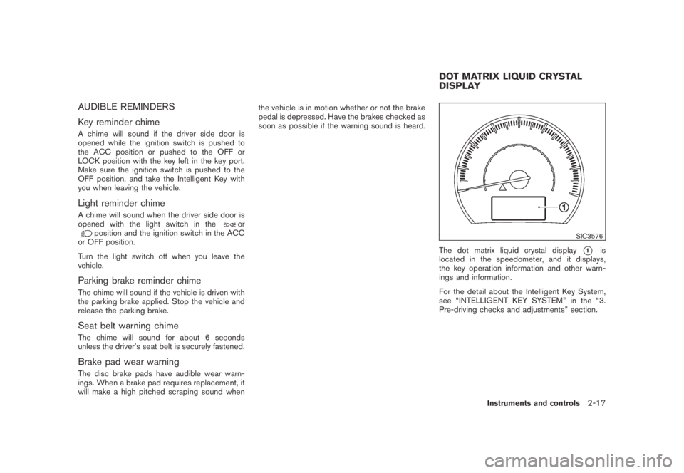
The dot matrix liquid crystal display*1is
located in the speedometer, and it displays,
the key operation information and other warn-
ings and information.
For the detail about the Intelligent Key System,
see “INTELLIGENT KEY SYSTEM” in the “3.
Pre-driving checks and adjustments” section.
DOT MATRIX LIQUID CRYSTAL
DISPLAY
Instruments and controls2-17
Page 134 of 443
Black plate (134,1)
Model "Z51-D" EDITED: 2007/ 10/ 2
SPA2033
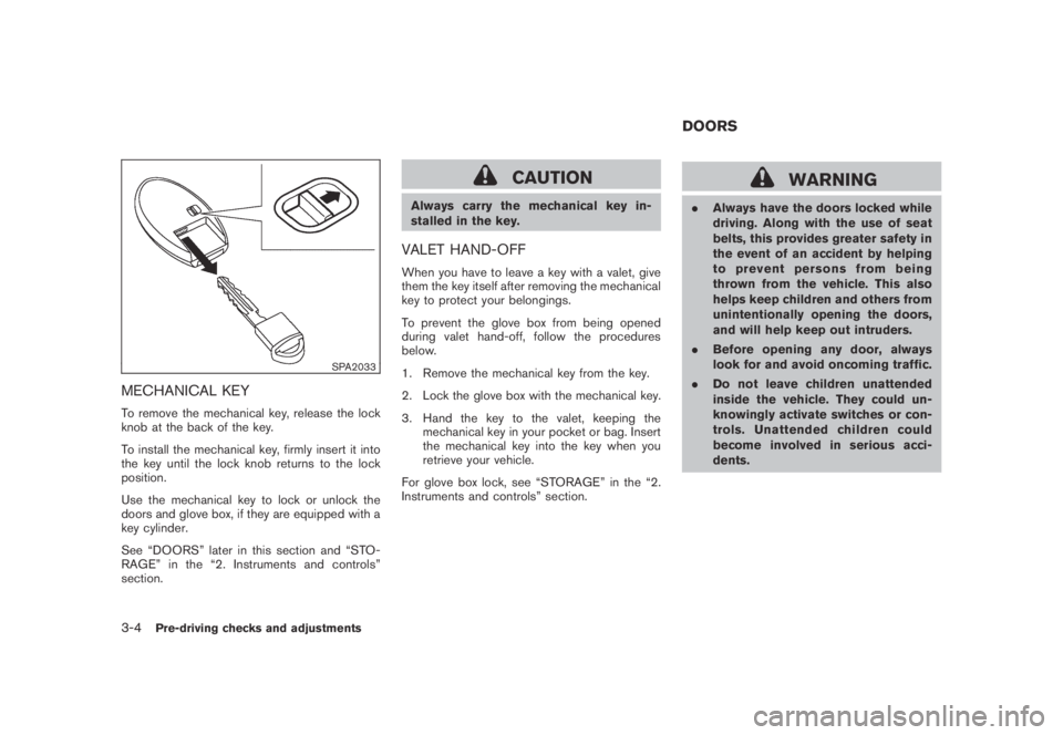
MECHANICAL KEY
To remove the mechanical key, release the lock
knob at the back of the key.
To install the mechanical key, firmly insert it into
the key until the lock knob returns to the lock
position.
Use the mechanical key to lock or unlock the
doors and glove box, if they are equipped with a
key cylinder.
See “DOORS” later in this section and “STO-
RAGE” in the “2. Instruments and controls”
section.
CAUTION
Always carry the mechanical key in-
stalled in the key.
VALET HAND-OFF
When you have to leave a key with a valet, give
them the key itself after removing the mechanical
key to protect your belongings.
To prevent the glove box from being opened
during valet hand-off, follow the procedures
below.
1. Remove the mechanical key from the key.
2. Lock the glove box with the mechanical key.
3. Hand the key to the valet, keeping the
mechanical key in your pocket or bag. Insert
the mechanical key into the key when you
retrieve your vehicle.
For glove box lock, see “STORAGE” in the “2.
Instruments and controls” section.
WARNING
.Always have the doors locked while
driving. Along with the use of seat
belts, this provides greater safety in
the event of an accident by helping
to prevent persons from being
thrown from the vehicle. This also
helps keep children and others from
unintentionally opening the doors,
and will help keep out intruders.
.Before opening any door, always
look for and avoid oncoming traffic.
.Do not leave children unattended
inside the vehicle. They could un-
knowingly activate switches or con-
trols. Unattended children could
become involved in serious acci-
dents.
DOORS
3-4Pre-driving checks and adjustments
Page 155 of 443
Black plate (155,1)
Model "Z51-D" EDITED: 2007/ 10/ 2
WARNING
.Do not adjust the steering wheel
while driving. You could lose control
of your vehicle and cause an acci-
dent.
.Do not adjust the steering wheel
any closer to you than is necessary
for proper steering operation and
comfort. The driver’s air bag inflates
with great force. If you are unrest-
rained, leaning forward, sitting side-
ways or out of position in any way,
you are at greater risk of injury or
death in a crash. You may also
receive serious or fatal injuries from
the air bag if you are up against it
when it inflates. Always sit back
against the seatback and as far
away as practical from the steering
wheel. Always use the seat belts.
SPA2443
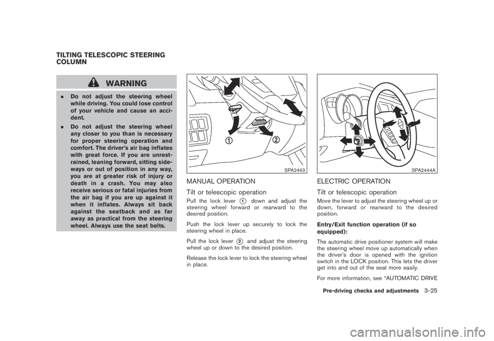
MANUAL OPERATION
Tilt or telescopic operation
Pull the lock lever*1down and adjust the
steering wheel forward or rearward to the
desired position.
Push the lock lever up securely to lock the
steering wheel in place.
Pull the lock lever
*2and adjust the steering
wheel up or down to the desired position.
Release the lock lever to lock the steering wheel
in place.
SPA2444A
ELECTRIC OPERATION
Tilt or telescopic operation
Move the lever to adjust the steering wheel up or
down, forward or rearward to the desired
position.
Entry/Exit function operation (if so
equipped):
The automatic drive positioner system will make
the steering wheel move up automatically when
the driver’s door is opened with the ignition
switch in the LOCK position. This lets the driver
get into and out of the seat more easily.
For more information, see “AUTOMATIC DRIVE
TILTING TELESCOPIC STEERING
COLUMN
Pre-driving checks and adjustments3-25
Page 160 of 443
Black plate (160,1)
Model "Z51-D" EDITED: 2007/ 10/ 2
The automatic drive positioner system has two
features:
.Entry/exit function
.Memory storage
ENTRY/EXIT FUNCTION
This system is designed so that the driver’s seat
and steering column will automatically move
when the selector lever is in the P (Park)
position. This allows the driver to get into and
out of the driver’s seat more easily.
The driver’s seat will slide backward and the
steering wheel will move up when the driver’s
door is opened with the ignition switch in the
LOCK position and the key not inserted in the
key port.
The driver’s seat and steering wheel will return
to the previous positions when the ignition
switch is pushed to the ACC position.
The driver’s seat will not return to the previous
positions if the seat or steering adjusting switch
is operated when the seat is at the exit position.
Cancel or activate entry/exit function
The selector lever must be in the P (Park)
position with the ignition switch in the OFF
position after the driver’s door is opened.
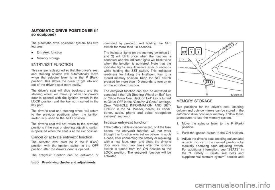
The entry/exit function can be activated orcanceled by pressing and holding the SET
switch for more than 10 seconds.
The indicator lights on the memory switches (1
and 2) will blink once when the function is
canceled, and the indicator lights will blink twice
when the function is activated. Note that the
indicator lights may illuminate after 5 seconds
while holding the SET switch. This indicates
readiness for linking the Intelligent Key to a
stored memory position. Keep the SET switch
pressed for more than 10 seconds to turn on or
off the entry/exit function.
The entry/exit function can also be activated or
canceled if the “Lift Steering Wheel on Exit” key
or “Slide Driver Seat Back on Exit” key is turned
to ON or OFF in the “Comfort & Conv.” settings.
(See “VEHICLE INFORMATION AND SET-
TINGS” in the “4. Monitor, heater, air condi-
tioner, audio, phone and voice recognition
systems” section.)
Initialize entry/exit function
If the battery cable is disconnected, or if the fuse
opens, the entry/exit function will not work
though this function was set on before. In such
a case, after connecting the battery or replacing
with a new fuse, open and close the driver’s
door more than two times after the ignition
switch is turned from the ON position to the
LOCK position. The entry/exit function will be
activated.
SPA2445
MEMORY STORAGE
Two positions for the driver’s seat, steering
column and outside mirrors can be stored in the
automatic drive positioner memory. Follow these
procedures to use the memory system.
1. Move the selector lever to the P (Park)
position.
2. Push the ignition switch to the ON position.
3. Adjust the driver’s seat, steering column and
outside mirrors to the desired positions by
manually operating each adjusting switch.
For additional information, see “SEATS” in
the “1. Safety — Seats, seat belts and
supplemental restraint system” section and
AUTOMATIC DRIVE POSITIONER (if
so equipped)
3-30Pre-driving checks and adjustments
Page 161 of 443
Black plate (161,1)
Model "Z51-D" EDITED: 2007/ 10/ 2
“TILTING TELESCOPIC STEERING COL-
UMN” earlier in this section and “OUTSIDE
MIRRORS” earlier in this section.
4. Push the SET switch and, within 5 seconds,
push the memory switch (1 or 2) .
The indicator light for the pushed memory
switch will stay on for approximately 5
seconds after pushing the switch.
If memory is stored in the same memory
switch, the previous memory will be deleted.
Linking key to a stored memory position
The key can be linked to a stored memory
position with the following procedure.
1. Follow one of the steps for storing a memory
position.
.While the indicator light for the memory
switch being set is illuminated for 5 sec-
onds, push the
button on the key.
.Push the ignition switch to the OFF position,
and then push the SET switch. Push the
button while pushing the memory
button while the indicator light stays on for
approximately 5 seconds.
If the indicator light blinks, the key is linked to
that memory setting.
Push the ignition switch to the OFF position, andthen push the
button on the key. The
driver’s seat, steering wheel and outside mirrors
will move to the memorized position.
Confirming memory storage
.Push the ignition switch to the ON position
and push the SET switch. If the main
memory has not been stored, the indicator
light will come on for approximately 0.5
second. When the memory has stored in
position, the indicator light will stay on for
approximately 5 seconds.
.If the battery cable is disconnected, or if the
fuse opens, the memory will be canceled. In
this case, reset the desired position using
the previous procedure.
.If optional keys are added to your vehicle,
the memory storage procedure to switch 1
or 2 and linking key procedure to a stored
memory position should be performed again
for each key. For additional Intelligent Key
information, see “KEYS” earlier in this
section.
Selecting the memorized position
1. Move the selector lever to the P (Park)
position.
2. Use one of the following methods to move
the driver’s seat, the outside mirrors and the
steering wheel..Push the ignition switch to the ON
position and push the memory switch
(1 or 2) .
.Within 45 seconds of opening the
driver’s door, push the memory switch
(1 or 2) .
The driver’s seat, steering column and
outside mirrors will move to the memorized
position with the indicator light flashing, and
then the light will stay on for approximately 5
seconds.
SYSTEM OPERATION
The automatic drive positioner system will not
work or will stop operating under the following
conditions:
.When the vehicle speed is above 4 MPH (7
km/h) (entry/exit function) .
.When the vehicle is driven (memory sto-
rage) .
.When the adjusting switch for the driver’s
seat and steering column is turned on while
the automatic drive positioner is operating.
.When the seat, steering column and outside
mirrors have already been moved to the
memorized position.
.When no position is stored in the memory
switch.
Pre-driving checks and adjustments3-31