2009 NISSAN LATIO wiring
[x] Cancel search: wiringPage 385 of 4331
AV
N
O P
CONTENTS
AUDIO, VISUAL, NAVIGATION & TELEPHONE SYS-
TEM
SERVICE INFORMATION .. ..........................2
PRECAUTIONS .............................................. .....2
Precaution for Supplemental Restraint System
(SRS) "AIR BAG" and "SEAT BELT PRE-TEN-
SIONER" ............................................................. ......
2
PREPARATION .............................................. .....3
Commercial Service Tool .................................... ......3
AUDIO ............................................................ .....4
Component Parts Location .................................. ......4
System Description ............................................. ......4
Schematic ........................................................... ......6
Wiring Diagram - AUDIO - ................................... ......8
Audio Unit (Base System) Harness Connector
Terminal Layout .................................................. ....
16
Terminal and Reference Value for Audio Unit
(Base System) ..................................................... ....
16
Audio Unit (Mid Level and Premium System) Har-
ness Connector Terminal Layout ........................ ....
17
Terminal and Reference Value for Audio Unit (Mid
Level and Premium System) ............................... ....
17
Subwoofer Harness Connector Terminal Layout
(Premium Audio System) .................................... ....
20
Terminal and Reference Value for Subwoofer
(Premium Audio System) .................................... ....
20
Satellite Radio Tuner Ha rness Connector Termi-
nal Layout ............................................................ ....
20
Terminal and Reference Value for Satellite Radio
Tuner ................................................................... ....
21
Trouble Diagnosis ............................................... ....21
Noise Inspection .................................................. ....22
Power Supply Circuit Inspection ......................... ....23
Satellite Radio Tuner (Fac tory Installed) Power
and Ground Supply Circuit Inspection ................. ....
24
Satellite Radio Tuner (Fac tory Installed) Commu-
nication Circuit Inspection ................................... ....
25
Satellite Radio Tuner (Fac tory Installed) Left
Channel Audio Signal Circuit Inspection ............. ....
27 Satellite Radio Tuner (Fac
tory Installed) Right
Channel Audio Signal Circuit Inspection ............. ....
27
Steering Switch Check (With Bluetooth) .............. ....28
Sound Is Not Heard from Front Door Speaker
(Base System) ..................................................... ....
30
Sound Is Not Heard from Rear Door Speaker
(Base System) ..................................................... ....
31
Sound Is Not Heard from Front Door Speaker or
Tweeter (Mid Level and Premium System) .............
32
Sound Is Not Heard from Rear Door Speaker (Mid
Level and Premium System) ............................... ....
33
Sound Is Not Heard from Subwoofer (Premium
System) ............................................................... ....
35
Removal and Installation ..................................... ....37
AUDIO ANTENNA ............................................. 42
Location of Antenna ............................................. ....42
Removal and Installation of Roof Antenna ..............42
TELEPHONE ..................................................... 44
Component Parts and Harness Connector Loca-
tion ....................................................................... ....
44
System Description .............................................. ....44
Wiring Diagram - H/PHON - ................................ ....46
Bluetooth Control Unit Harness Connector Termi-
nal Layout ............................................................ ....
48
Terminal and Reference Value for Bluetooth Con-
trol Unit ................................................................ ....
48
Bluetooth Control Unit Se lf-Diagnosis Function ......49
Workflow .............................................................. ....50
Power Supply and Ground Circuit Inspection for
Bluetooth Control Unit .. ...........................................
50
Basic Inspection of Hands-Free Phone ............... ....51
Steering Wheel Audio Co ntrol Switch Does Not
Operate ................................................................ ....
52
Voice Activated Control Fu nction Does Not Oper-
ate ........................................................................ ....
53
Removal and Installation ..................................... ....55
Page 389 of 4331
AV
N
O P
• to audio unit terminal 21 (with premium system)
• through body grounds M57 and M61 and
• to subwoofer terminal 3 (with premium system)
• through body grounds B7 and B19.
Then audio signals are supplied
• through audio unit terminals 2, 3, 4, 5, 11, 12, 13, and 14
• to terminals + and - of front door speaker LH and RH and
• to terminals + and - of tweeter LH and RH and
• to terminals + and - of rear door speaker LH and RH and
• to terminals 2 and 6 of subwoofer (with premium system).
Steering Wheel Audio Contro l Switches (with Bluetooth)
When one of steering wheel audio control switches is pus hed, the resistance in steering switch circuit changes
depending on which button is pushed.
Satellite Radio Tuner (Pre-wiring) The satellite radio tuner pre-wiring allows connection of a satellite radio tuner.
Power is supplied at all times
• through 20A fuse (No. 27, located in the fuse and fusible link box)
• to satellite radio tuner pre-wiring terminal 32.
With the ignition switch in the ACC or ON position, power is supplied
• through 10A fuse (No. 20, located in the fuse and fusible link box)
• to satellite radio tuner pre-wiring terminal 36.
Then audio signals are supplied
• through satellite radio tuner pre-wiring terminals 21, 22, 23 and 24
• to audio unit terminals 41, 42, 43 and 44.
Satellite Radio Tuner (Factory Installed)
Power is supplied at all times
• through 20A fuse (No. 27, located in the fuse and fusible link box)
• to satellite radio tuner terminal 32.
With the ignition switch in the ACC or ON position, power is supplied
• through 10A fuse (No. 20, located in the fuse and fusible link box)
• to satellite radio tuner terminal 36.
Ground is supplied through the case of the satellite radio tuner.
Then audio signals are supplied
• through satellite radio tuner terminals 21, 22, 23 and 24
• to audio unit terminals 41, 42, 43 and 44.
Ground is supplied through the case of the satellite radio tuner.
SPEED SENSITIVE VOLUME SYSTEM (MID LEVEL AND PREMIUM SYSTEM) Volume level of this system goes up and down automatica lly in proportion to the vehicle speed. The control
level can be selected by the customer. Refer to Owner's Manual for operating instructions.
Page 462 of 4331
BL
N
O P
CONTENTS
BODY, LOCK & SECURITY SYSTEM
SERVICE INFORMATION .. ..........................4
PRECAUTIONS .............................................. .....4
Precaution for Supplemental Restraint System
(SRS) "AIR BAG" and "SEAT BELT PRE-TEN-
SIONER" ............................................................. ......
4
Precaution Necessary fo r Steering Wheel Rota-
tion After Battery Disconnect ............................... ......
4
Precaution for Procedure without Cowl Top Cover ......5
Precaution for Work ............................................ ......5
PREPARATION .............................................. .....6
Special Service Tool ........................................... ......6
Commercial Service Tool .................................... ......6
SQUEAK AND RATTLE TROUBLE DIAG-
NOSES ........................ ........................................7
Work Flow ........................................................... ......7
Generic Squeak and Rattle Troubleshooting ...... ......9
Diagnostic Worksheet ......................................... ....11
HOOD ............................................................. ....13
Fitting Adjustment ............................................... ....13
Removal and Installation .........................................14
Removal and Installation of Hood Lock Control .. ....15
Hood Lock Control Inspec tion .................................17
RADIATOR CORE SUPPORT ....................... ....19
Removal and Installation .........................................19
FRONT FENDER ............................................ ....21
Removal and Installation .........................................21
POWER DOOR LOCK SYSTEM .................... ....22
Component Parts and Harness Connector Loca-
tion ...................................................................... ....
22
System Description ............................................. ....23
CAN Communication System Description ........... ....25
Schematic ........................................................... ....26
Wiring Diagram - D/LOCK - ................................. ....27
Schematic ........................................................... ....31
Wiring Diagram - D/LOCK - ................................. ....32 Terminal and Reference
Value for BCM ..................37
Work Flow ............................................................ ....41
CONSULT-III Function (B CM) .................................41
Trouble Diagnosis Symptom Chart ...................... ....43
BCM Power Supply and Ground Circuit Inspection ....43
Door Switch Check (Hatchback) .......................... ....44
Door Switch Check (Sedan) ................................ ....47
Key Switch (Insert) Check ................................... ....48
Door Lock and Unlock Switch Check .................. ....49
Front Door Lock Assembly LH (Actuator) Check .....52
Door Lock Actuator Check (Front RH and Rear
LH/RH) ................................................................. ....
53
Front Door Key Cylinder S witch LH Check ..............54
Passenger Select Unlock Relay Circuit Inspection
(With Intelligent Key) ........................................... ....
55
REMOTE KEYLESS ENTRY SYSTEM ............. 58
Component Parts and Harness Connector Loca-
tion ....................................................................... ....
58
System Description .............................................. ....58
CAN Communication System Description ........... ....60
Schematic ............................................................ ....61
Wiring Diagram - KEYLES - ................................ ....62
Terminal and Reference Value for BCM ..................65
How to Perform Trouble Diagnosis ...................... ....69
Preliminary Check ............................................... ....69
CONSULT-III Function (B CM) .................................69
Work Flow ............................................................ ....71
Trouble Diagnosis Symptom Chart ...................... ....71
Keyfob Battery and Function Check .................... ....72
ACC Switch Check .............................................. ....74
Door Switch Check (Hatchback) .......................... ....74
Door Switch Check (Sedan) ................................ ....76
Key Switch (Insert) Check ................................... ....78
Hazard Function Check ....................................... ....78
Horn Function Check ........................................... ....79
Interior Lamp and Ignition Keyhole Illumination
Function Check .................................................... ....
79
Remote Keyless Entry Rece iver Check ...................80
Keyfob Function (Lock) Check ............................ ....82
Page 464 of 4331
BL
N
O P
Check Trunk Lid Opener S
witch Circuit (With Intel-
ligent Key) ........................................................... ..
212
Check Trunk Release Solenoid Circuit ............... ..214
FUEL FILLER LID OPENER .......................... ..217
Removal and Installation of Fuel Filler Lid Opener ..217
VEHICLE SECURITY (THEFT WARNING)
SYSTEM ......................................................... ..
218
Component Parts and Harness Connector Loca-
tion ...................................................................... ..
218
System Description ............................................. ..219
CAN Communication System Description ........... ..221
Schematic ........................................................... ..222
Wiring Diagram - VEHSEC - ............................... ..223
Terminal and Reference Value for BCM ............. ..227
Terminal and Re ference Value for Intelligent Key
Unit ...................................................................... ..
231
CONSULT-III Function (BCM) ............................. ..233
Trouble Diagnosis ............................................... ..235
Preliminary Check ............................................... ..235
Symptom Chart ................................................... ..237
Diagnosis Procedure 1 ........................................ ..238
Diagnosis Procedure 2 ........................................ ..241
Diagnosis Procedure 3 ........................................ ..242
Diagnosis Procedure 4 ........................................ ..242
Diagnosis Procedure 5 ........................................ ..242
Diagnosis Procedure 6 ........................................ ..242
Diagnosis Procedure 7 ........................................ ..242
Diagnosis Procedure 8 ........................................ ..244
Diagnosis Procedure 9 ........................................ ..245 NATS (Nissan Anti-Theft System) ................
248
Component Parts and Harness Connector Loca-
tion ....................................................................... ..
248
System Description .............................................. ..248
System Composition ............................................ ..249
ECM Re-communicating Function ....................... ..249
Wiring Diagram - NATS - ..................................... ..251
Terminal and Reference Value for BCM ................252
CONSULT-III Function ........................................ ..256
Trouble Diagnosis Procedure .............................. ..257
Trouble Diagnosis ................................................ ..259
Diagnosis Procedure 1 ........................................ ..260
Diagnosis Procedure 2 ........................................ ..262
Diagnosis Procedure 3 ........................................ ..263
Diagnosis Procedure 4 ........................................ ..264
Diagnosis Procedure 5 ........................................ ..265
Diagnosis Procedure 6 ........................................ ..266
How to Replace NATS Antenna Amp .................. ..266
BODY REPAIR ................................................ 267
Body Exterior Paint Color .................................... ..267
Body Component Parts ....................................... ..269
Corrosion Protection ............................................ ..274
Body Sealing ....................................................... ..278
Body Construction ............................................... ..284
Body Alignment ................................................... ..286
Handling Precaution for Plastics .......................... ..303
Precaution in Repairing High Strength Steel ....... ..307
Foam Repair ........................................................ ..310
Replacement Operation ....................................... ..313
Page 470 of 4331
BL
N
O P
SILICONE GREASE
Used instead of UHMW tape that will be visible or not fit.
Note: Will only last a few months.
SILICONE SPRAY
Use when grease cannot be applied.
DUCT TAPE
Use to eliminate movement.
CONFIRM THE REPAIR Confirm that the cause of a noise is repaired by test driving the vehicle. Operate the vehicle under the same
conditions as when the noise originally occurred. Refer to the notes on the Diagnostic Worksheet.
Generic Squeak and Rattle Troubleshooting INFOID:0000000004304978
Refer to Table of Contents for specific component removal and installation information.
INSTRUMENT PANEL Most incidents are caused by contact and movement between:
1. The cluster lid A and instrument panel
2. Acrylic lens and combination meter housing
3. Instrument panel to front pillar garnish
4. Instrument panel to windshield
5. Instrument panel mounting pins
6. Wiring harnesses behind the combination meter
7. A/C defroster duct and duct joint
These incidents can usually be located by tapping or moving the components to duplicate the noise or by
pressing on the components while driving to stop the noi se. Most of these incidents can be repaired by apply-
ing felt cloth tape or silicone spray (in hard to reach areas). Urethane pads can be used to insulate wiring har-
ness.
CAUTION:
Do not use silicone spray to isolate a squeak or ra ttle. If you saturate the area with silicone, you will
not be able to recheck the repair.
CENTER CONSOLE Components to pay attention to include:
1. Shifter assembly cover to finisher
2. A/C control unit and cluster lid C
3. Wiring harnesses behind audio and A/C control unit
The instrument panel repair and isolation pr ocedures also apply to the center console.
DOORS Pay attention to the:
1. Finisher and inner panel making a slapping noise
2. Inside handle escutcheon to door finisher
3. Wiring harnesses tapping
4. Door striker out of alignment causing a popping noise on starts and stops
Tapping or moving the components or pressing on them wh ile driving to duplicate the conditions can isolate
many of these incidents. You can usually insulate the ar eas with felt cloth tape or insulator foam blocks from
the NISSAN Squeak and Rattle Kit (J-43980) to repair the noise.
TRUNK Trunk noises are often caused by a loose jack or loose items put into the trunk by the owner.
In addition look for:
1. Trunk lid bumpers out of adjustment
2. Trunk lid striker out of adjustment
3. The trunk lid torsion bars knocking together
4. A loose license plate or bracket
Page 488 of 4331

BL
N
O P
Wiring Diagram - D/LOCK -
INFOID:0000000004304990
WITHOUT INTELLIGENT KEY SYSTEM B
Page 634 of 4331
BL
N
O P
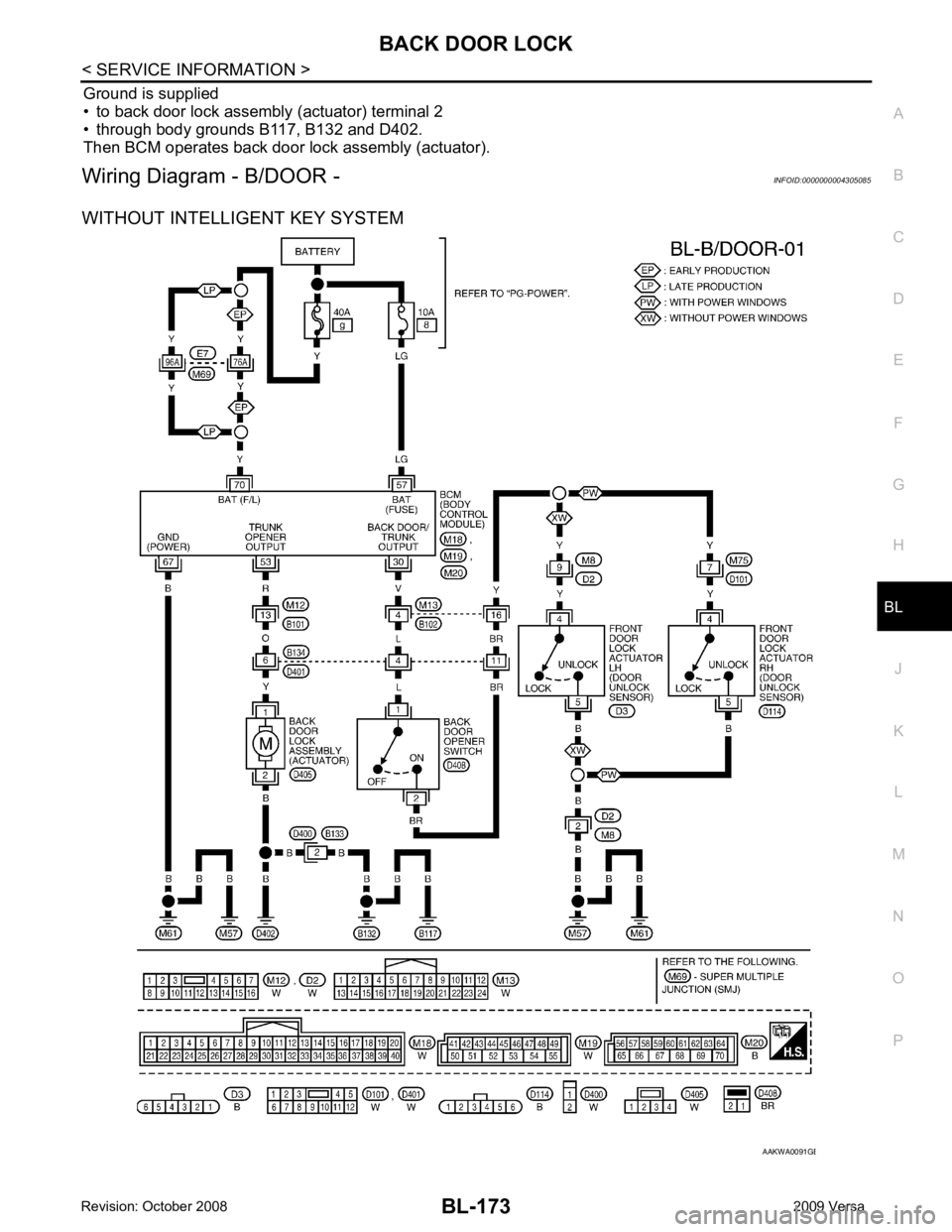
Ground is supplied
• to back door lock assembly (actuator) terminal 2
• through body grounds B117, B132 and D402.
Then BCM operates back door lock assembly (actuator).
Wiring Diagram - B/DOOR - INFOID:0000000004305085
WITHOUT INTELLIGENT KEY SYSTEM B
Page 658 of 4331
BL
N
O P
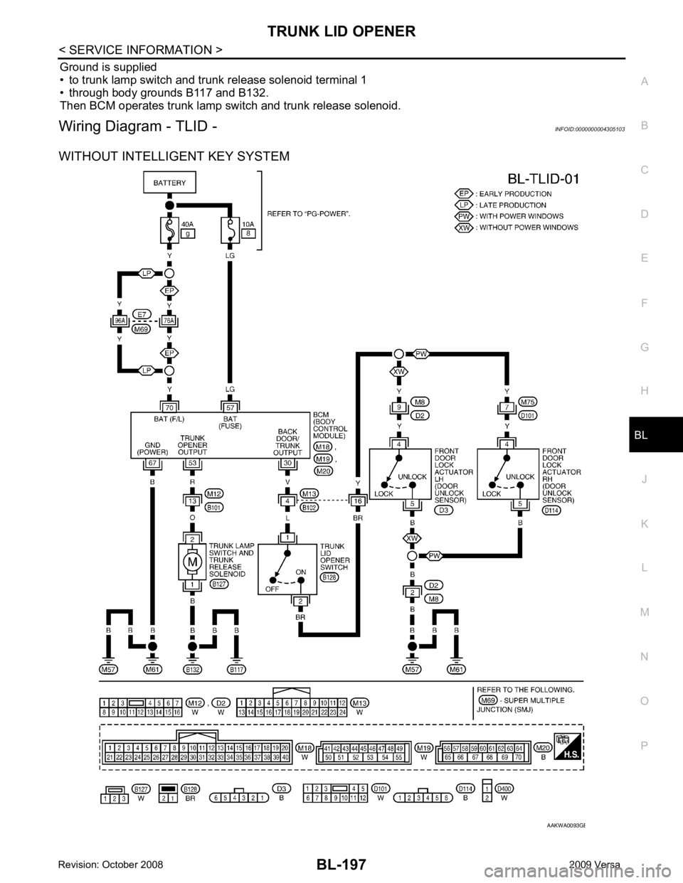
Ground is supplied
• to trunk lamp switch and trunk release solenoid terminal 1
• through body grounds B117 and B132.
Then BCM operates trunk lamp switch and trunk release solenoid.
Wiring Diagram - TLID - INFOID:0000000004305103
WITHOUT INTELLIGENT KEY SYSTEM B