Page 103 of 4331
OK >> GO TO 7.
NG >> GO TO 2. (HR16DE),
EC-627, " Wiring Diagram " (MR Type 1) or
EC-1139," Wiring Diagram " (MR Type 2).
OK or NG OK >> GO TO 3.
NG >> Repair or replace damaged parts. OK >> GO TO 7.
NG >> GO TO 4. Item
Connec-
tor Terminal Condition Judge-
ment stan- dard
(Approx.)
A/T fluid
temperature
sensor E32 47 - 42 When A/T fluid tempera-
ture is 20 °C (68 °F). 1.5 V
When A/T fluid tempera- ture is 80 °C (176 °F). 0.5 V
Page 107 of 4331
Diagnosis Procedure without CONSULT-III " .
4. If the check result is NG, go to AT-103, " Diagnosis Procedure " .
Wiring Diagram - AT - VSSA/T INFOID:0000000004305359
Page 108 of 4331
AT
N
O P
TCM TERMINALS AND REFERENCE VALUES
Refer to AT-77, " TCM Terminal and Reference Value " .
Diagnosis Procedure INFOID:0000000004305360OK >> GO TO 8.
NG >> GO TO 2. " Wiring Diagram - AT - MAIN " and
AT-102, " Wiring Diagram - AT - VSSA/T " .
3. If OK, check the pulse when vehicle cruises.
OK or NG OK >> GO TO 8.
NG >> GO TO 3. B
Page 110 of 4331
AT
N
O P
3. Check continuity between TCM connector terminals and revolu-
tion sensor harness connector terminal. Refer to AT-50, " Circuit
Diagram " and
AT-169, " Wiring Diagram - AT - MAIN " .
4. If OK, check harness for short to ground and short to power.
5. Reinstall any part removed.
OK or NG OK >> 10A fuse (No.49, located in the IPDM
E/R) or ignition switch are malfunctioning.
NG >> Repair open circuit or short to ground or short to power in harness or connectors. OK >> GO TO 5.
NG >> Repair open circuit or short to ground or short to power
in harness or connectors. DTC Confirmation Procedure " .
OK or NG OK >>
INSPECTION END
NG >> GO TO 5. Item Connector Terminal Continuity
TCM E31 10 Yes
Revolution sensor F38 1
TCM E31 19 Yes
Revolution sensor F38 1
Page 112 of 4331
AT
N
O P
Wiring Diagram - AT - ENGSS
INFOID:0000000004305366
TCM TERMINALS AND REFERENCE VALUES Refer to AT-77, " TCM Terminal and Reference Value " .
Page 116 of 4331

AT
N
O P
5. Accelerate vehicle to 20 to 25 km/h (12 to 16 MPH) under the following conditions and release the accel-
erator pedal completely.
THROTTLE POSI: Less th an 1.0/8 (at all times during step 4)
SLCT LVR POSI: “D” position
- Make sure that “GEAR” shows “2” after releasing pedal.
6. Depress accelerator pedal to WOT (more than 7.0/ 8 of “THROTTLE POSI”) quickly from a speed of 20 to
25 km/h (12 to 16 MPH) until “TESTING” changes to “STOP VEHICLE” or “COMPLETED”. (It will take
approximately 3 seconds.)
If the check result NG appears on CONSULT-III screen, go to AT-111, " Diagnosis Procedure " .
If “STOP VEHICLE” appears on CONSULT-III screen, go to the following step.
- Make sure that “GEAR” shows “1” when depressing accelerator pedal to WOT.
- If “TESTING” does not appear on CONSULT-III fo r a long time, select “SELF-DIAG RESULTS” for
“TRANSMISSION”. In case a DTC other than “P0731 A/T 1ST GR FNCTN” is shown, refer to AT-79," CONSULT-III Function (TRANSMISSION) " .
7. Stop vehicle.
8. Follow the instruction displayed. (Check for normal shifting referring to the table below.)
9. Make sure that “OK” is disp layed. (If “NG” is displayed, refer to “Diagnostic Procedure”.)
Refer to AT-111, " Diagnosis Procedure " .
Refer to AT-64, " Vehicle Speed at Which Gear Shifting Occurs " .
WITH GST
Follow the procedure “WITH CONSULT-III”.
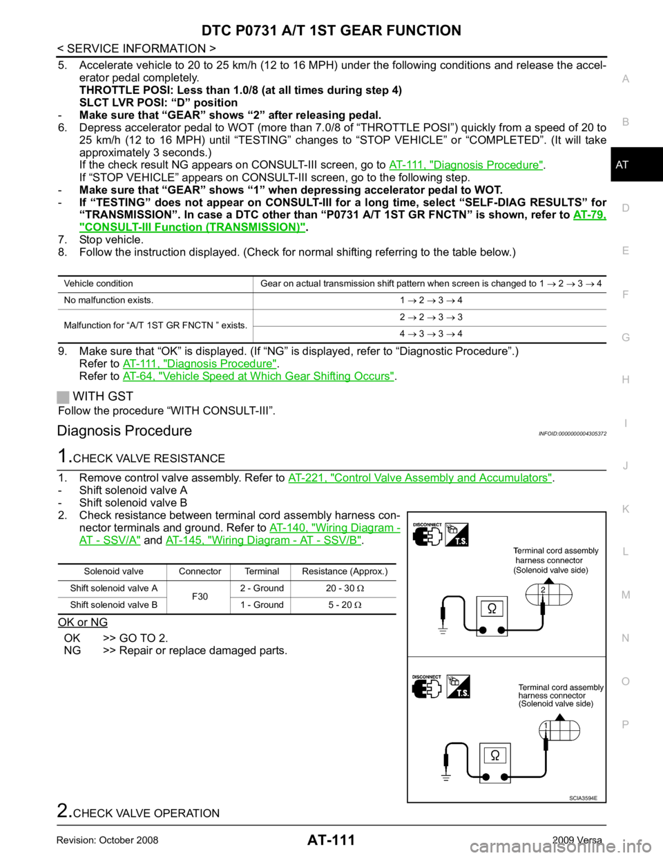
Diagnosis Procedure INFOID:0000000004305372Control Valve Assembly and Accumulators " .
- Shift solenoid valve A
- Shift solenoid valve B
2. Check resistance between terminal cord assembly harness con- nector terminals and ground. Refer to AT-140, " Wiring Diagram -
AT - SSV/A " and
AT-145, " Wiring Diagram - AT - SSV/B " .
OK or NG OK >> GO TO 2.
NG >> Repair or replace damaged parts. Solenoid valve Connector Terminal Resistance (Approx.)
Shift solenoid valve A F302 - Ground 20 - 30
Ω
Shift solenoid valve B 1 - Ground 5 - 20 Ω
Page 117 of 4331
Control Valve Assembly and Accumulators " .
- Shift solenoid valve A
- Shift solenoid valve B
2. Check solenoid valve by listening for its operating sound while
applying battery voltage to the terminals and ground. Refer to
AT-140, " Wiring Diagram - AT - SSV/A " and
AT-145, " Wiring Dia-
gram - AT - SSV/B " .
OK or NG OK >> GO TO 3.
NG >> Repair or replace shift solenoid valve assembly. Control Valve Assembly " .
2. Check to ensure that:
- Valve, sleeve and plug slide along valve bore under their own weight.
- Valve, sleeve and plug are free from burrs, dents and scratches.
- Control valve springs are free from damage, deformation and fatigue.
- Hydraulic line is free from obstacles.
OK or NG OK >> GO TO 4.
NG >> Repair control valve assembly. DTC Confirmation Procedure " .
OK or NG OK >>
INSPECTION END
NG >> Check control valve again. If NG, repair or replace control valve assembly.
Page 119 of 4331

Diagnosis Procedure " .
If “STOP VEHICLE” appears on CONSUL T-III screen, go to following step.
- Make sure that “GEAR” shows “2” wh en depressing accelerator pedal to WOT.
- If “TESTING” does not appear on CONSULT-III fo r a long time, select “SELF-DIAG RESULTS” for
“TRANSMISSION”. In case a DTC other than “P0732 A/T 2ND GR FNCTN” is shown, refer to AT-79," CONSULT-III Function (TRANSMISSION) " .
7. Stop vehicle.
8. Follow the instruction displayed. (Check for normal shifting referring to the table below.)
9. Make sure that “OK” is displayed. (If “NG” is displayed, refer to “Diagnostic Procedure”.)
Refer to AT-114, " Diagnosis Procedure " .
Refer to AT-64, " Vehicle Speed at Which Gear Shifting Occurs " .
WITH GST
Follow the procedure “WITH CONSULT-III”.
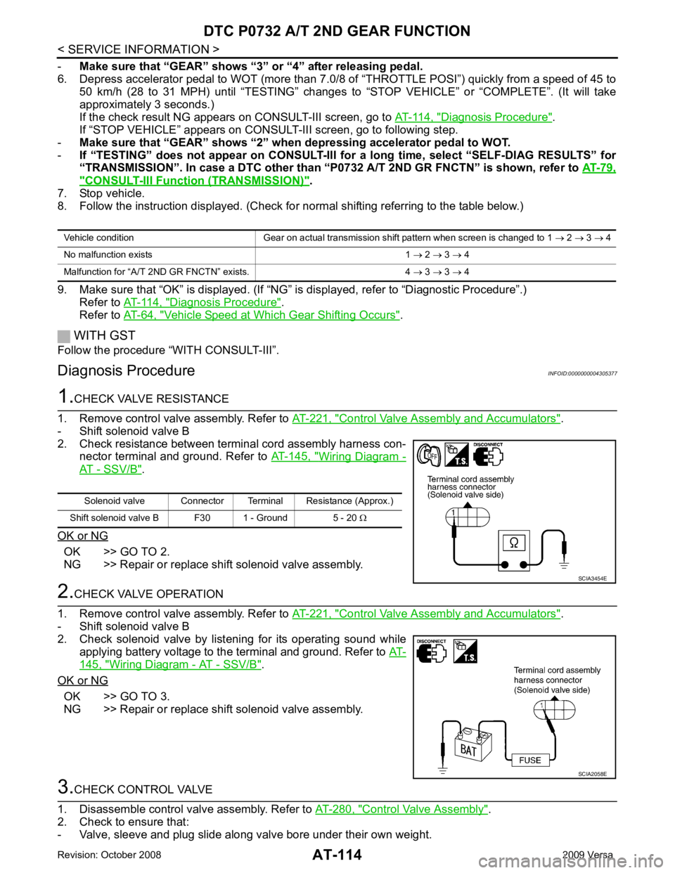
Diagnosis Procedure INFOID:0000000004305377Control Valve Assembly and Accumulators " .
- Shift solenoid valve B
2. Check resistance between terminal cord assembly harness con- nector terminal and ground. Refer to AT-145, " Wiring Diagram -
AT - SSV/B " .
OK or NG OK >> GO TO 2.
NG >> Repair or replace shift solenoid valve assembly. Control Valve Assembly and Accumulators " .
- Shift solenoid valve B
2. Check solenoid valve by listening for its operating sound while applying battery voltage to the terminal and ground. Refer to AT-145, " Wiring Diagram - AT - SSV/B " .
OK or NG OK >> GO TO 3.
NG >> Repair or replace shift solenoid valve assembly. Control Valve Assembly " .
2. Check to ensure that:
- Valve, sleeve and plug slide along valve bore under their own weight. Vehicle condition Gear on actual transmission shift pattern when screen is changed to 1
→ 2 → 3 → 4
No malfunction exists 1 → 2 → 3 → 4
Malfunction for “A/T 2ND GR FNCTN” exists. 4 → 3 → 3 → 4 Solenoid valve Connector Terminal Resistance (Approx.)
Shift solenoid valve B F30 1 - Ground 5 - 20 Ω SCIA2058E