Page 3256 of 4331

GI
N
O P
2. Use the Intelligent Key or mechanical key to turn the ignition switch to the
″ACC ″ position. At this time, the
steering lock will be released.
3. Disconnect both battery cables. The steering lock will remain released and the steering wheel can be
rotated.
4. Perform the necessary repair operation.
5. When the repair work is completed, return the ignition switch to the ″LOCK ″ position before connecting
the battery cables. (At this time, the steering lock mechanism will engage.)
6. Perform a self-diagnosis check of al l control units using CONSULT-III.
General Precaution INFOID:0000000004307347
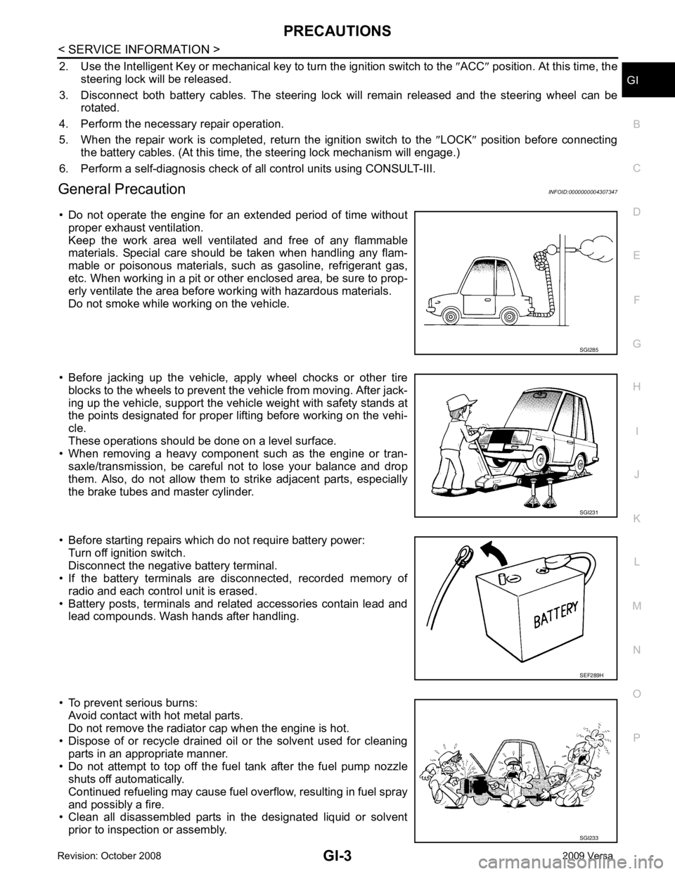
• Do not operate the engine for an extended period of time without proper exhaust ventilation.
Keep the work area well ventilated and free of any flammable
materials. Special care should be taken when handling any flam-
mable or poisonous materials, such as gasoline, refrigerant gas,
etc. When working in a pit or ot her enclosed area, be sure to prop-
erly ventilate the area before working with hazardous materials.
Do not smoke while working on the vehicle.
• Before jacking up the vehicle, apply wheel chocks or other tire blocks to the wheels to prevent t he vehicle from moving. After jack-
ing up the vehicle, support the vehicle weight with safety stands at
the points designated for proper lifting before working on the vehi-
cle.
These operations should be done on a level surface.
• When removing a heavy component such as the engine or tran-
saxle/transmission, be careful not to lose your balance and drop
them. Also, do not allow them to strike adjacent parts, especially
the brake tubes and master cylinder.
• Before starting repairs which do not require battery power: Turn off ignition switch.
Disconnect the negative battery terminal.
• If the battery terminals are disconnected, recorded memory of
radio and each control unit is erased.
• Battery posts, terminals and related accessories contain lead and lead compounds. Wash hands after handling.
• To prevent serious burns: Avoid contact with hot metal parts.
Do not remove the radiator cap when the engine is hot.
• Dispose of or recycle drained oil or the solvent used for cleaning
parts in an appropriate manner.
• Do not attempt to top off the fuel tank after the fuel pump nozzle shuts off automatically.
Continued refueling may cause fuel overflow, resulting in fuel spray
and possibly a fire.
• Clean all disassembled parts in the designated liquid or solvent
prior to inspection or assembly. SGI231
SGI233
Page 3280 of 4331

GI
N
O P
The customer's concern may occur during hot weather or after car
has sat for a short time. In such cases you will want to check for a
heat sensitive condition.
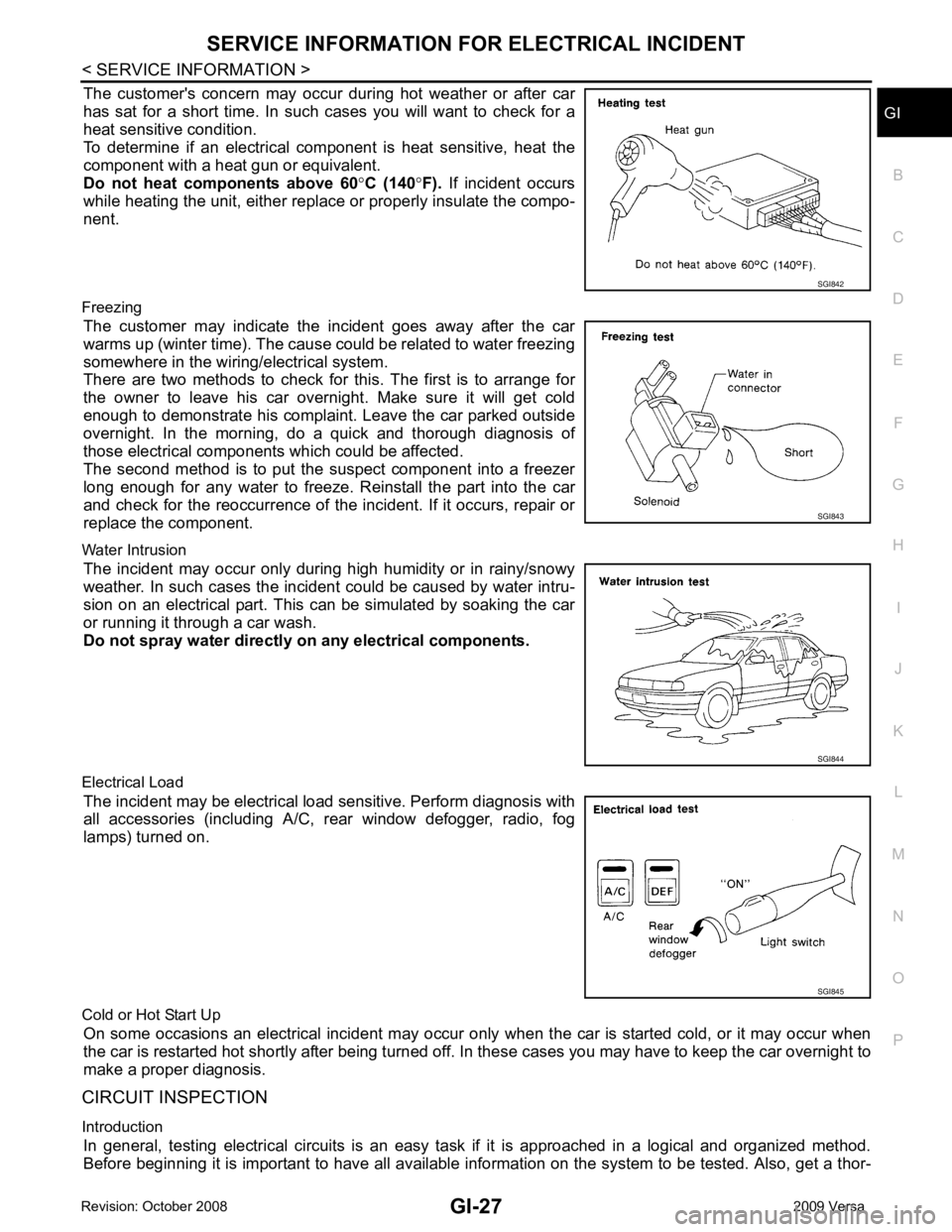
To determine if an electrical com ponent is heat sensitive, heat the
component with a heat gun or equivalent.
Do not heat components above 60 °C (140 °F). If incident occurs
while heating the unit, either replace or properly insulate the compo-
nent.
Freezing The customer may indicate the incident goes away after the car
warms up (winter time). The cause could be related to water freezing
somewhere in the wiring/electrical system.
There are two methods to check for this. The first is to arrange for
the owner to leave his car overnight. Make sure it will get cold
enough to demonstrate his complaint. Leave the car parked outside
overnight. In the morning, do a quick and thorough diagnosis of
those electrical components which could be affected.
The second method is to put the suspect component into a freezer
long enough for any water to freeze. Reinstall the part into the car
and check for the reoccurrence of the incident. If it occurs, repair or
replace the component.
Water Intrusion The incident may occur only during high humidity or in rainy/snowy
weather. In such cases the incident could be caused by water intru-
sion on an electrical part. This c an be simulated by soaking the car
or running it through a car wash.
Do not spray water directly on any electrical components.
Electrical Load The incident may be electrical load sensitive. Perform diagnosis with
all accessories (including A/C, rear window defogger, radio, fog
lamps) turned on.
Cold or Hot Start Up On some occasions an electrical incident may occur only when the car is started cold, or it may occur when
the car is restarted hot shortly after being turned off. In these cases you may have to keep the car overnight to
make a proper diagnosis.
CIRCUIT INSPECTION
Introduction In general, testing electrical circuits is an easy ta sk if it is approached in a logical and organized method.
Before beginning it is important to have all available in formation on the system to be tested. Also, get a thor- SGI843
SGI845
Page 4144 of 4331
Required Procedure After Battery Disconnection " .
Required Procedure Afte r Battery Disconnection INFOID:0000000004678559
Battery wedge bracket bolt : 14.2 N·m (1.4 kg-m, 10 ft-lb)
Battery terminal nut : 5.4 N·m (0.55 kg-m, 48 in-lb)
System Item Reference
Glasses, Windows & Mirrors Power Window System Initialization Refer to
GW-31, " Power Window
Auto Operation Initialization " .
Roof Sunroof Memory Reset/Initialization Refer to
RF-11, " System Descrip-
tion " .
Audio-Visual System Audio (Radio Preset) Refer to Owner’s Manual
Page 4274 of 4331

WT
N
O P
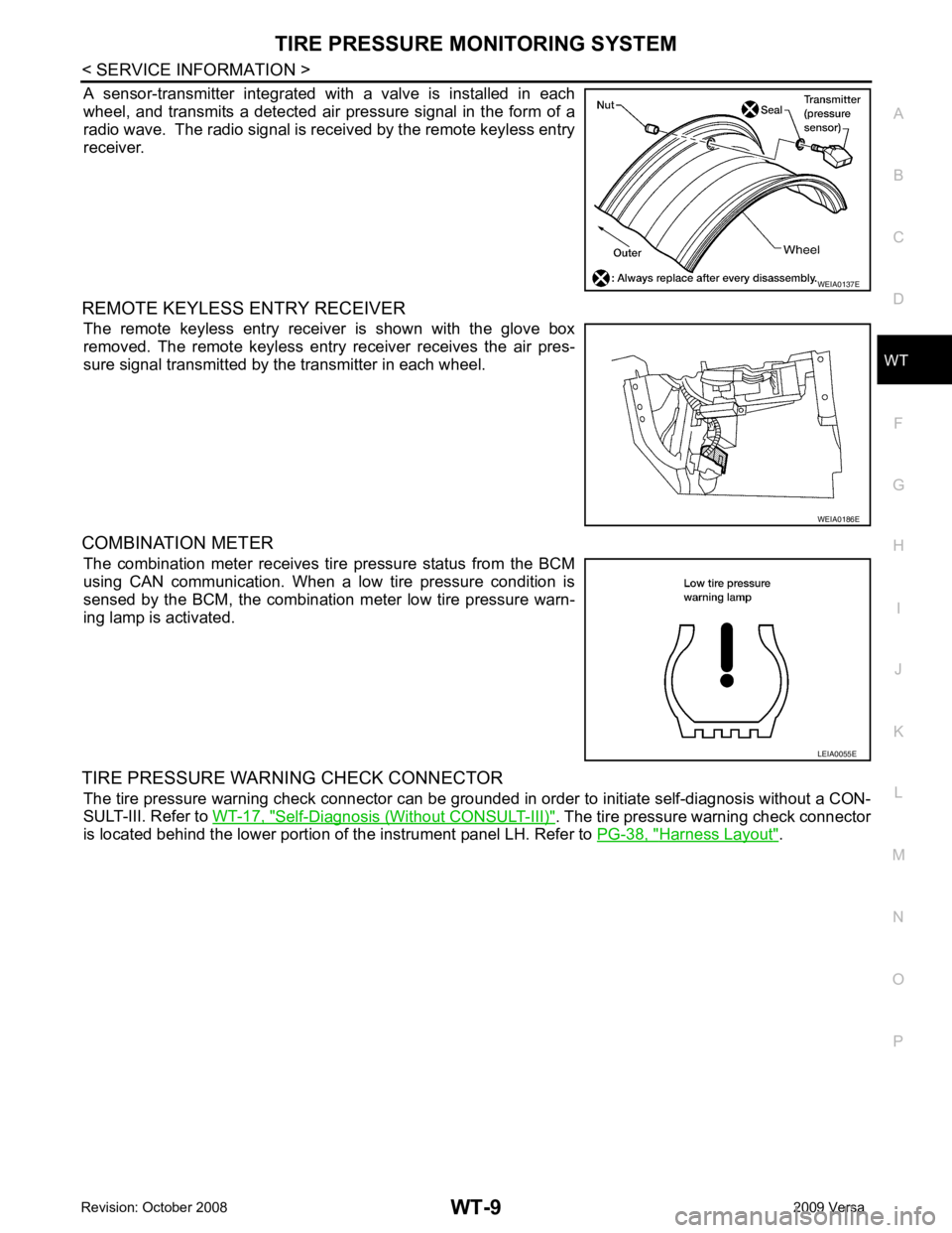
A sensor-transmitter integrated with a valve is installed in each
wheel, and transmits a detected air pressure signal in the form of a
radio wave. The radio signal is received by the remote keyless entry
receiver.
REMOTE KEYLESS ENTRY RECEIVER The remote keyless entry receiver is shown with the glove box
removed. The remote keyless entry receiver receives the air pres-
sure signal transmitted by the transmitter in each wheel.
COMBINATION METER The combination meter receives tire pressure status from the BCM
using CAN communication. When a low tire pressure condition is
sensed by the BCM, the combination meter low tire pressure warn-
ing lamp is activated.
TIRE PRESSURE WARNING CHECK CONNECTOR The tire pressure warning check connector can be grounded in order to initiate self-diagnosis without a CON-
SULT-III. Refer to WT-17, " Self-Diagnosis (Without CONSULT-III) " . The tire pressure warning check connector
is located behind the lower portion of the instrument panel LH. Refer to PG-38, " Harness Layout " . WEIA0186E
LEIA0055E
Page:
< prev 1-8 9-16 17-24