2009 NISSAN LATIO fuel type
[x] Cancel search: fuel typePage 2871 of 4331
![NISSAN LATIO 2009 Service Repair Manual FUEL PUMP
EC-1515
< SERVICE INFOMATION >
[MR TYPE 2] C
D E
F
G H
I
J
K L
M A EC
NP
O
Diagnosis Procedure
INFOID:00000000045004181.
CHECK OVERALL FUNCTION
1. Turn ignition switch ON.
2. Pinch fuel feed NISSAN LATIO 2009 Service Repair Manual FUEL PUMP
EC-1515
< SERVICE INFOMATION >
[MR TYPE 2] C
D E
F
G H
I
J
K L
M A EC
NP
O
Diagnosis Procedure
INFOID:00000000045004181.
CHECK OVERALL FUNCTION
1. Turn ignition switch ON.
2. Pinch fuel feed](/manual-img/5/57359/w960_57359-2870.png)
FUEL PUMP
EC-1515
< SERVICE INFOMATION >
[MR TYPE 2] C
D E
F
G H
I
J
K L
M A EC
NP
O
Diagnosis Procedure
INFOID:00000000045004181.
CHECK OVERALL FUNCTION
1. Turn ignition switch ON.
2. Pinch fuel feed hose (1) with two fingers.
- Illustration shows the view with intake air duct removed.
OK or NG OK >>
INSPECTION END
NG >> GO TO 2. 2.
CHECK FUEL PUMP POWER SUPPLY CIRCUIT-I
1. Turn ignition switch OFF.
2. Disconnect ECM harness connector.
3. Turn ignition switch ON.
4. Check voltage between ECM terminal 23 and ground with CON-
SULT-III or tester.
OK or NG OK >> GO TO 5.
NG >> GO TO 3. 3.
CHECK FUEL PUMP POWER SUPPLY CIRCUIT-II
1. Turn ignition switch OFF.
2. Disconnect IPDM E/R harness connector E46.
3. Turn ignition switch ON.
4. Check voltage between IPDM E/R terminal 47 and ground with
CONSULT-III or tester.
OK or NG OK >> GO TO 4.
NG >> GO TO 11.
TERMI-
NAL NO. WIRE
COLOR ITEM CONDITION DATA (DC Voltage)
23 GR Fuel pump relay [Ignition switch: ON]
• For 1 second after turning ignition switch ON
[Engine is running] 0 - 1.0V
[Ignition switch: ON]
• More than 1 second after turning ignition
switch ON BATTERY VOLTAGE
(11 - 14V) Fuel pressure pulsation should
be felt on the fuel feed
hose for 1 second after ignition switch is turned ON. BBIA0712E
Voltage: Battery voltage
PBIA9573J
Voltage: Battery voltage
PBIB3319E
Page 2872 of 4331
![NISSAN LATIO 2009 Service Repair Manual EC-1516< SERVICE INFOMATION >
[MR TYPE 2]
FUEL PUMP 4.
DETECT MALFUNCTIONING PART
Check the following.
• Harness connectors E8, F8
• Harness for open or short between IPDM E/R and ECM
>> Repair op NISSAN LATIO 2009 Service Repair Manual EC-1516< SERVICE INFOMATION >
[MR TYPE 2]
FUEL PUMP 4.
DETECT MALFUNCTIONING PART
Check the following.
• Harness connectors E8, F8
• Harness for open or short between IPDM E/R and ECM
>> Repair op](/manual-img/5/57359/w960_57359-2871.png)
EC-1516< SERVICE INFOMATION >
[MR TYPE 2]
FUEL PUMP 4.
DETECT MALFUNCTIONING PART
Check the following.
• Harness connectors E8, F8
• Harness for open or short between IPDM E/R and ECM
>> Repair open circuit or short to ground or short to power in harness or connectors. 5.
CHECK FUEL PUMP POWER SUPPLY CIRCUIT-III
1. Turn ignition switch OFF.
2. Reconnect all harness connectors disconnected.
3. Disconnect “fuel level sensor unit and fuel pump” harness con- nector (1).
- Illustration shows the view with inspection hole cover removed.
4. Turn ignition switch ON.
5. Check voltage between “fuel level sensor unit and fuel pump” terminal 1 and ground with CONSULT-III or tester.
OK or NG OK >> GO TO 9.
NG >> GO TO 6. 6.
CHECK 15A FUSE
1. Turn ignition switch OFF.
2. Disconnect 15A fuse.
3. Check 15A fuse.
OK or NG OK >> GO TO 7.
NG >> Replace fuse. 7.
CHECK FUEL PUMP POWER SUPPLY CIRCUIT-IV
1. Disconnect IPDM E/R harness connector E45.
2. Check harness continuity between IPDM E/R terminal 36 and “fuel level sensor unit and fuel pump” termi-
nal 1. Refer to Wiring Diagram.
3. Also check harness for short to ground and short to power.
OK or NG OK >> GO TO 11.
NG >> GO TO 8. 8.
DETECT MALFUNCTIONING PART
Check the following.
• Harness connectors M69, E7
• Harness connectors M12, B101 BBIA0702E
Voltage: Battery voltage should exist for 1 second
after ignition switch is turned ON. PBIB0795E
Continuity should exist.
Page 2873 of 4331
![NISSAN LATIO 2009 Service Repair Manual FUEL PUMP
EC-1517
< SERVICE INFOMATION >
[MR TYPE 2] C
D E
F
G H
I
J
K L
M A EC
NP
O
• Harness for open or short between IPDM E/R
and “fuel level sensor unit and fuel pump”
>> Repair open circu NISSAN LATIO 2009 Service Repair Manual FUEL PUMP
EC-1517
< SERVICE INFOMATION >
[MR TYPE 2] C
D E
F
G H
I
J
K L
M A EC
NP
O
• Harness for open or short between IPDM E/R
and “fuel level sensor unit and fuel pump”
>> Repair open circu](/manual-img/5/57359/w960_57359-2872.png)
FUEL PUMP
EC-1517
< SERVICE INFOMATION >
[MR TYPE 2] C
D E
F
G H
I
J
K L
M A EC
NP
O
• Harness for open or short between IPDM E/R
and “fuel level sensor unit and fuel pump”
>> Repair open circuit or short to ground or short to power in harness or connectors. 9.
CHECK FUEL PUMP GROUND CIRCUIT
1. Check harness continuity between “fuel level sensor unit and fuel pump” terminal 3 and ground.
Refer to Wiring Diagram.
2. Also check harness for short to power.
OK or NG OK >> GO TO 10.
NG >> Repair or replace harness or connectors. 10.
CHECK FUEL PUMP
Refer to EC-1517, " Component Inspection " .
OK or NG OK >> GO TO 11.
NG >> Replace fuel pump. 11.
CHECK INTERMITTENT INCIDENT
Refer to EC-1138 .
OK or NG OK >> Replace IPDM E/R. Refer to
PG-27, " Removal and Installation of IPDM E/R " .
NG >> Repair or replace harness or connectors.
Component Inspection INFOID:0000000004500419
FUEL PUMP 1. Disconnect “fuel level sensor unit and fuel pump” harness connector.
2. Check resistance between “fuel level sensor unit and fuel pump” terminals 1 and 3.
3. If NG, replace “fuel level sensor unit and fuel pump”.
Removal and Installation INFOID:0000000004500420
FUEL PUMP Refer to FL-5 .
Continuity should exist.
Resistance: Approximately 0.2 - 5.0 Ω [at 25 °C (77 °F)] SEC918C
Page 2882 of 4331
![NISSAN LATIO 2009 Service Repair Manual EC-1526< SERVICE INFOMATION >
[MR TYPE 2]
IGNITION SIGNAL
7. Remove fuel pump fuse (1) in IPDM E/R (2) to release fuel pres- sure.
NOTE:
Do not use CONSULT-III to releas e fuel pressure, or f NISSAN LATIO 2009 Service Repair Manual EC-1526< SERVICE INFOMATION >
[MR TYPE 2]
IGNITION SIGNAL
7. Remove fuel pump fuse (1) in IPDM E/R (2) to release fuel pres- sure.
NOTE:
Do not use CONSULT-III to releas e fuel pressure, or f](/manual-img/5/57359/w960_57359-2881.png)
EC-1526< SERVICE INFOMATION >
[MR TYPE 2]
IGNITION SIGNAL
7. Remove fuel pump fuse (1) in IPDM E/R (2) to release fuel pres- sure.
NOTE:
Do not use CONSULT-III to releas e fuel pressure, or fuel pres-
sure applies again during the following procedure.
- : Vehicle front
8. Start engine.
9. After engine stalls, crank it two or three times to release all fuel
pressure.
10. Turn ignition switch OFF.
11. Remove all ignition coil harness connectors to avoid the electri-
cal discharge from the ignition coils.
12. Remove ignition coil and spark plug of the cylinder to be checked.
13. Crank engine for 5 seconds or more to remove combustion gas in the cylinder.
14. Connect spark plug and harness connector to ignition coil.
15. Fix ignition coil using a rope etc. with gap of 13 - 17 mm (0.52 - 0.66 in) between the edge of the spark plug and grounded metal
portion as shown in the figure.
16. Crank engine for about 3 seconds, and check whether spark is generated between the spark plug and the grounded metal por-
tion.
CAUTION:
• Do not approach to the spar k plug and the ignition coil
within 50cm. Be careful not to get an electrical shock
while checking, because the el ectrical discharge voltage
becomes 20kV or more.
• It might cause to damage the igni tion coil if the gap of more than 17 mm (0.66 in) is taken.
NOTE:
When the gap is less than 13 mm (0.52 in), the sp ark might be generated even if the coil is mal-
functioning.
17. If NG, replace ignition coil with power transistor.
CONDENSER-2
1. Turn ignition switch OFF.
2. Disconnect condenser-2 harness connector.
3. Check resistance between condenser-2 terminals 1 and 2.
4. If NG, replace condenser-2.
Removal and Installation INFOID:0000000004500425
IGNITION COIL WITH POWER TRANSISTOR
Refer to EM-153 .
Spark should be generated. PBIB2958E
PBIB2325E
Resistance: Above 1 M
Ω [at 25 °C (77 °F)] PBIB0794E
Page 3036 of 4331

EM
NP
O
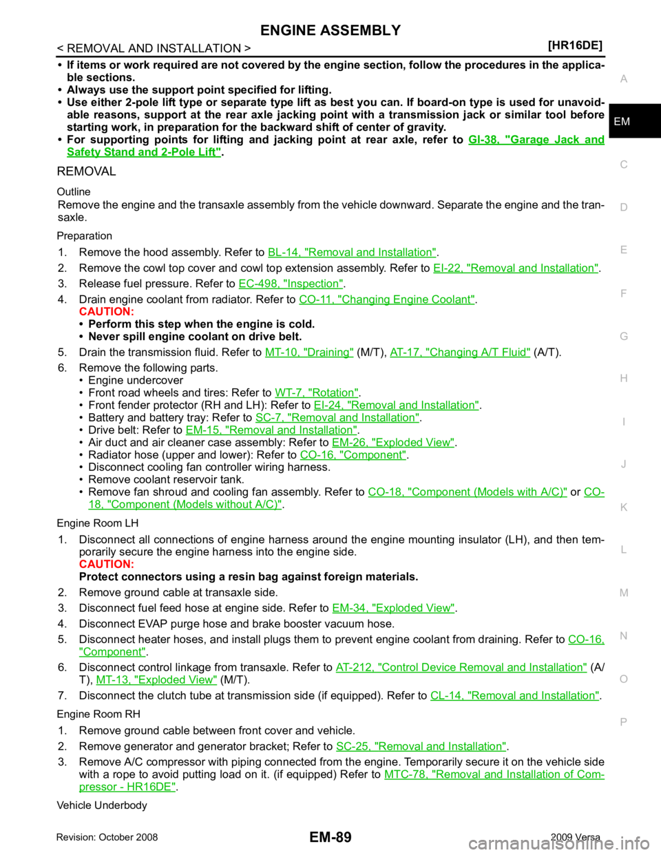
• If items or work required are not covered by the
engine section, follow the procedures in the applica-
ble sections.
• Always use the support poin t specified for lifting.
• Use either 2-pole lift type or separate type lift as best you can. If board-on type is used for unavoid-
able reasons, support at the rear axle jacking point with a transmission jack or similar tool before
starting work, in prepar ation for the backward shif t of center of gravity.
• For supporting points fo r lifting and jacking point at rear axle, refer to GI-38, " Garage Jack and
Safety Stand and 2-Pole Lift " .
REMOVAL
Outline Remove the engine and the transaxle assembly from t he vehicle downward. Separate the engine and the tran-
saxle.
Preparation 1. Remove the hood assembly. Refer to BL-14, " Removal and Installation " .
2. Remove the cowl top cover and cowl top extension assembly. Refer to EI-22, " Removal and Installation " .
3. Release fuel pressure. Refer to EC-498, " Inspection " .
4. Drain engine coolant from radiator. Refer to CO-11, " Changing Engine Coolant " .
CAUTION:
• Perform this step when the engine is cold.
• Never spill engine coolant on drive belt.
5. Drain the transmission fluid. Refer to MT-10, " Draining " (M/T),
AT-17, " Changing A/T Fluid " (A/T).
6. Remove the following parts. • Engine undercover
• Front road wheels and tires: Refer to WT-7, " Rotation " .
• Front fender protector (RH and LH): Refer to EI-24, " Removal and Installation " .
• Battery and battery tray: Refer to SC-7, " Removal and Installation " .
• Drive belt: Refer to EM-15, " Removal and Installation " .
• Air duct and air cleaner case assembly: Refer to EM-26, " Exploded View " .
• Radiator hose (upper and lower): Refer to CO-16, " Component " .
• Disconnect cooling fan controller wiring harness.
• Remove coolant reservoir tank.
• Remove fan shroud and cooling fan assembly. Refer to CO-18, " Component (Models with A/C) " or
CO- 18, " Component (Models without A/C) " .
Engine Room LH 1. Disconnect all connections of engine harness around the engine mounting insulator (LH), and then tem- porarily secure the engine harness into the engine side.
CAUTION:
Protect connectors using a resin bag against foreign materials.
2. Remove ground cable at transaxle side.
3. Disconnect fuel feed hose at engine side. Refer to EM-34, " Exploded View " .
4. Disconnect EVAP purge hose and brake booster vacuum hose.
5. Disconnect heater hoses, and install plugs them to prevent engine coolant from draining. Refer to CO-16," Component " .
6. Disconnect control linkage from transaxle. Refer to AT-212, " Control Device Removal and Installation " (A/
T), MT-13, " Exploded View " (M/T).
7. Disconnect the clutch tube at tr ansmission side (if equipped). Refer to CL-14, " Removal and Installation " .
Engine Room RH 1. Remove ground cable between front cover and vehicle.
2. Remove generator and generator bracket; Refer to SC-25, " Removal and Installation " .
3. Remove A/C compressor with piping connected from t he engine. Temporarily secure it on the vehicle side
with a rope to avoid putting load on it. (if equipped) Refer to MTC-78, " Removal and Installation of Com-
pressor - HR16DE " .
Vehicle Underbody
Page 3103 of 4331

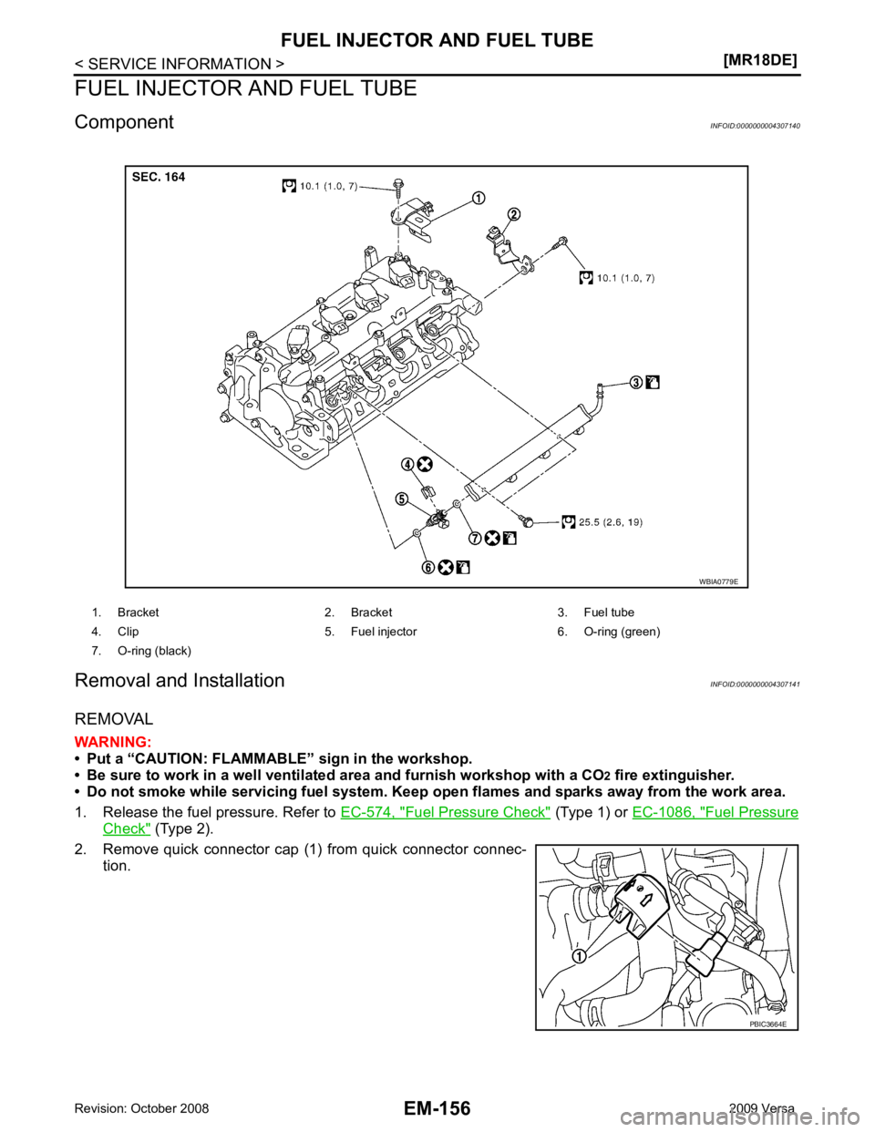
Fuel Pressure Check " (Type 1) or
EC-1086, " Fuel Pressure
Check " (Type 2).
2. Remove quick connector cap (1) from quick connector connec- tion.
1. Bracket 2. Bracket 3. Fuel tube
4. Clip 5. Fuel injector 6. O-ring (green)
7. O-ring (black) PBIC3664E
Page 3117 of 4331

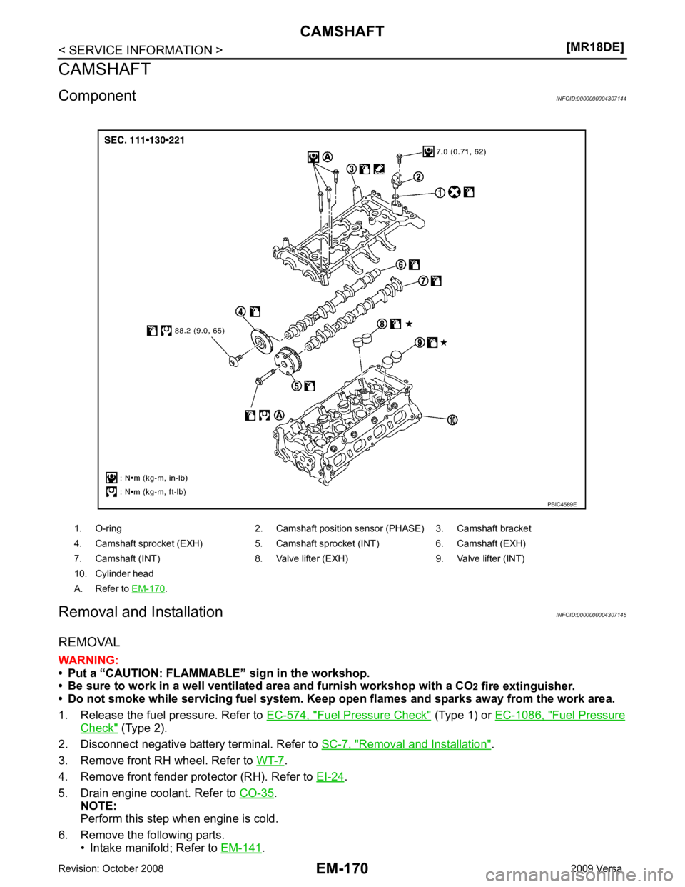
Fuel Pressure Check " (Type 1) or
EC-1086, " Fuel Pressure
Check " (Type 2).
2. Disconnect negative battery terminal. Refer to SC-7, " Removal and Installation " .
3. Remove front RH wheel. Refer to WT-7 .
4. Remove front fender protector (RH). Refer to EI-24 .
5. Drain engine coolant. Refer to CO-35 .
NOTE:
Perform this step when engine is cold.
6. Remove the following parts. • Intake manifold; Refer to EM-141 .
1. O-ring 2. Camshaft po
sition sensor (PHASE) 3. Camshaft bracket
4. Camshaft sprocket (EXH) 5. Camshaft sprocket (INT) 6. Camshaft (EXH)
7. Camshaft (INT) 8. Valve lifter (EXH) 9. Valve lifter (INT)
10. Cylinder head
A. Refer to EM-170 .
Page 3118 of 4331

EM
NP
O
• Rocker cover; Refer to
EM-153 .
• Fuel tube and fuel injector assembly; Refer to EM-156 .
• Front cover, timing chain and related parts; Refer to EM-160 .
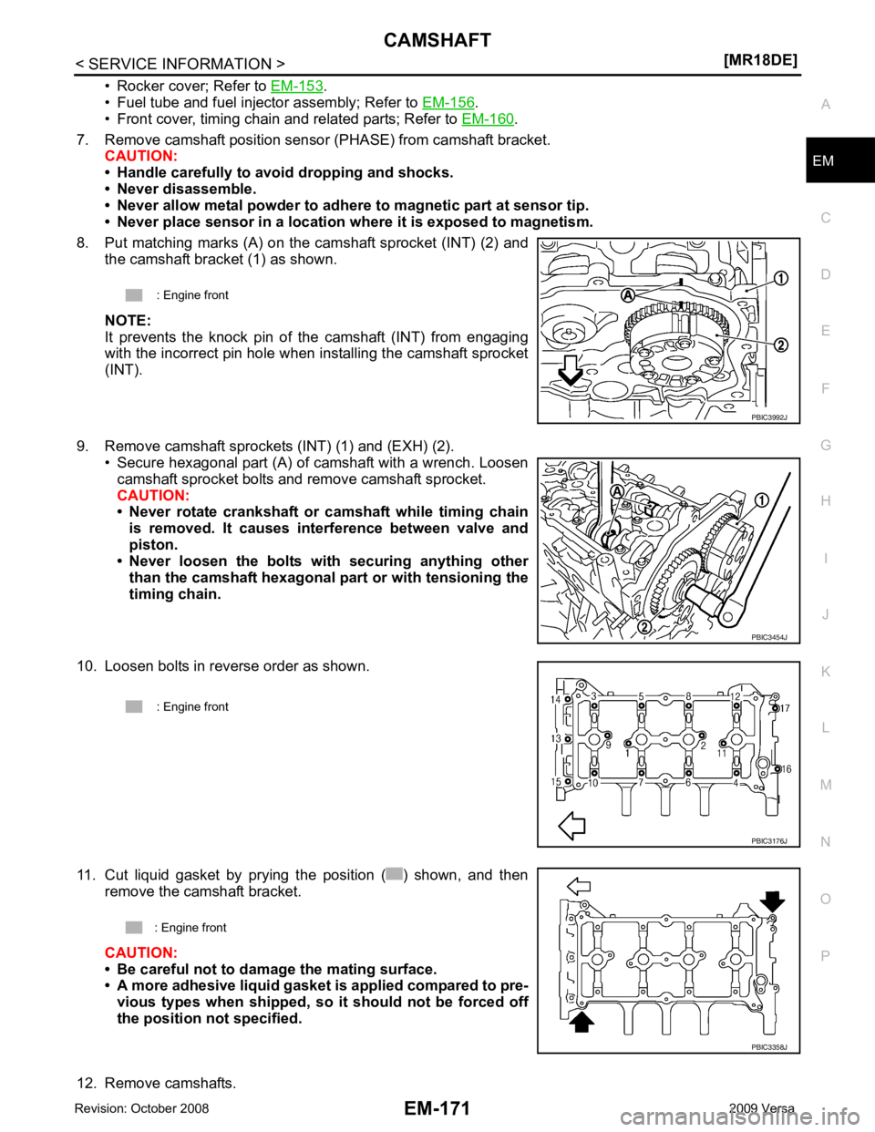
7. Remove camshaft position sensor (PHASE) from camshaft bracket. CAUTION:
• Handle carefully to avoid dropping and shocks.
• Never disassemble.
• Never allow metal powder to adhere to magnetic part at sensor tip.
• Never place sensor in a location wher e it is exposed to magnetism.
8. Put matching marks (A) on the camshaft sprocket (INT) (2) and the camshaft bracket (1) as shown.
NOTE:
It prevents the knock pin of the camshaft (INT) from engaging
with the incorrect pin hole when installing the camshaft sprocket
(INT).
9. Remove camshaft sprockets (INT) (1) and (EXH) (2). • Secure hexagonal part (A) of camshaft with a wrench. Loosen
camshaft sprocket bolts and remove camshaft sprocket.
CAUTION:
• Never rotate crankshaft or camshaft while timing chain
is removed. It causes interference between valve and
piston.
• Never loosen the bolts with securing anything other
than the camshaft hexagonal part or with tensioning the
timing chain.
10. Loosen bolts in reverse order as shown.
11. Cut liquid gasket by prying the position ( ) shown, and then remove the camshaft bracket.
CAUTION:
• Be careful not to damage the mating surface.
• A more adhesive liquid gasket is applied compared to pre-
vious types when shipped, so it should not be forced off
the position not specified.
12. Remove camshafts. : Engine front
PBIC3454J