2009 NISSAN LATIO service
[x] Cancel search: servicePage 3194 of 4331
![NISSAN LATIO 2009 Service Repair Manual EX-10< SERVICE INFORMATION >
[MR18DE]
EXHAUST SYSTEM
• Be careful not to cut your ha nd on heat insulator edges.
CAUTION:
• Use genuine NISSAN exhaust system parts or equi valent, which a NISSAN LATIO 2009 Service Repair Manual EX-10< SERVICE INFORMATION >
[MR18DE]
EXHAUST SYSTEM
• Be careful not to cut your ha nd on heat insulator edges.
CAUTION:
• Use genuine NISSAN exhaust system parts or equi valent, which a](/manual-img/5/57359/w960_57359-3193.png)
EX-10< SERVICE INFORMATION >
[MR18DE]
EXHAUST SYSTEM
• Be careful not to cut your ha nd on heat insulator edges.
CAUTION:
• Use genuine NISSAN exhaust system parts or equi valent, which are specially designed for heat
resistance, corrosion resistance and shape.
REMOVAL
Remove exhaust system components using power tools.
• Remove heated oxygen sensor using Tool as needed.
CAUTION:
Be careful not to damage heated oxygen sensor.
INSTALLATION
Installation is in the reverse order of removal.
CAUTION:
• Always replace exhaust gaskets and seal bear ings with new ones when installing.
• Before installing a new heated oxygen sensor, clean and apply an ti-seize lubricant to exhaust sys-
tem threads using suitable tool.
• Discard any heated oxygen sensor which has been dropped from a height of more than 0.5 m (19.7
in) onto a hard surface such as a co ncrete floor; install a new one.
• Do not over-tighten the heated oxygen sensor. Doing so may damage the heated oxygen sensor,
resulting in the MIL coming on.
• Remove deposits from the sealing surface of each connection. Connect them securely to avoid
exhaust leakage.
• Temporarily tighten nuts on the exhaust manifold side and bolts on the vehicle side. Check each part
for unusual interference, and then ti ghten them to the specified torque.
• When installing each mounting rubb er, avoid twisting or unusual extension in up/down and right/left
directions.
Exhaust Manifold to Exhaust Front Tube
1. Securely insert seal bearing (2) into exhaust manifold (1) side in the direction shown.
• Exhaust front tube (5)
CAUTION:
Be careful not to damage seal bearing surface when install-
ing.
2. Install spring (3), tighten nut (4). • Be careful that the stud bolt nut does not interfere with the
flanged area ( ).
• Make sure the spring (3) sits properly on the flange surface by aligning it to the locator dimples.
Exhaust Front Tube to Center Muffler
1. Securely insert seal bearing (2) into exhaust front tube (1) side in the direction shown.
• Center muffler (5)
CAUTION:
Be careful not to damage seal bearing surface when install-
ing.
2. Install spring (3), tighten bolt (4). • Be careful that the stud bolt does not interfere with the flanged
area ( ).
• Make sure the spring (3) sits properly on the flange surface by
aligning it to the locator dimples.
INSPECTION AFTER INSTALLATION Tool number : KV10114400 (J-38365)
Oxygen sensor thread cleaner : — (J-43897-18)
Oxygen sensor thread cleaner : — (J-43897-12) PBIC3797E
PBIC3798E
Page 3196 of 4331
FAX
N
O P
CONTENTS
FRONT AXLE
SERVICE INFORMATION .. ..........................2
PRECAUTIONS .............................................. .....2
Precaution for Supplemental Restraint System
(SRS) "AIR BAG" and "SEAT BELT PRE-TEN-
SIONER" ............................................................. ......
2
Precaution Necessary fo r Steering Wheel Rota-
tion After Battery Disconnect ............................... ......
2
Caution ................................................................ ......2
PREPARATION .............................................. .....4
Special Service Tool ........................................... ......4
Commercial Service Tool .................................... ......4
NOISE, VIBRATION AND HARSHNESS
(NVH) TROUBLESHOOTING ........................ .....5
NVH Troubleshooting Chart ................................ ......5 FRONT WHEEL HUB
AND KNUCKLE ............. 6
On-Vehicle Inspection and Service ..................... .....6
Removal and Installation ..................................... .....6
FRONT DRIVE SHAFT ...................................... 9
On-Vehicle Inspection and Service ..................... .....9
Removal and Installation (Left Side) .................... .....9
Removal and Installation (Right Side) ................. ....10
Disassembly and Assembly (Left Side) ............... ....13
Disassembly and Assembly (Right Side) ............. ....18
SERVICE DATA AND SPECIFICATIONS
(SDS) ................................................................. 25
Wheel Bearing ..................................................... ....25
Drive Shaft ........................................................... ....25
Dynamic Damper ................................................. ....25
Boot Bands .......................................................... ....25
Page 3198 of 4331
FAX
N
O P
• Before disassembling and assembling, clean the outside of parts.
• Prevention of the entry of foreign objects must be tak en into account during disassembly of the service loca-
tion.
• Disassembled parts must be carefully reassembled in the correct order. If work is interrupted, a clean cover
must be placed over parts.
• Paper shop cloths must be used. Fabric shop cloths must not be used because of danger of lint adhering to
parts.
• Disassembled parts (except for rubber parts) should be cleaned with kerosene which shall be removed by blowing with air or wiping with paper shop cloths.
Page 3203 of 4331
FAX-8< SERVICE INFORMATION >
FRONT WHEEL HUB AND KNUCKLE
12. Remove nuts and bolts, and then remove steering knuckle from strut assembly. Refer to FSU-10, " Component " .
INSPECTION AFTER REMOVAL
Wheel Hub and Knuckle Inspection
Check for any deformity, cracks, or other damage on t he wheel hub assembly and knuckle, replace if neces-
sary.
CAUTION:
The wheel hub assembly does not require maintenance. If any of the following symptoms are noted,
replace the wheel hub assembly.
• Growling noise is emitted from the wheel hub bearing during operation.
• Wheel hub bearing drags or turns roughly.
Ball Joint Inspection
Check boots of transverse link and steering outer socket ball joint for breakage, axial play, and torque. Refer to
FSU-15, " Removal and Installation " transverse link and
PS-13, " Disassembly and Assembly " steering outer
socket ball joint.
INSTALLATION
Installation is the reverse order of removal. Note the following:
• Perform the final tightening of each of parts under unladen conditions, which were removed when removing
wheel hub and bearing assembly and steering knuckl e. Check the wheel alignment. Refer to FSU-7, " Wheel
Alignment Inspection " .
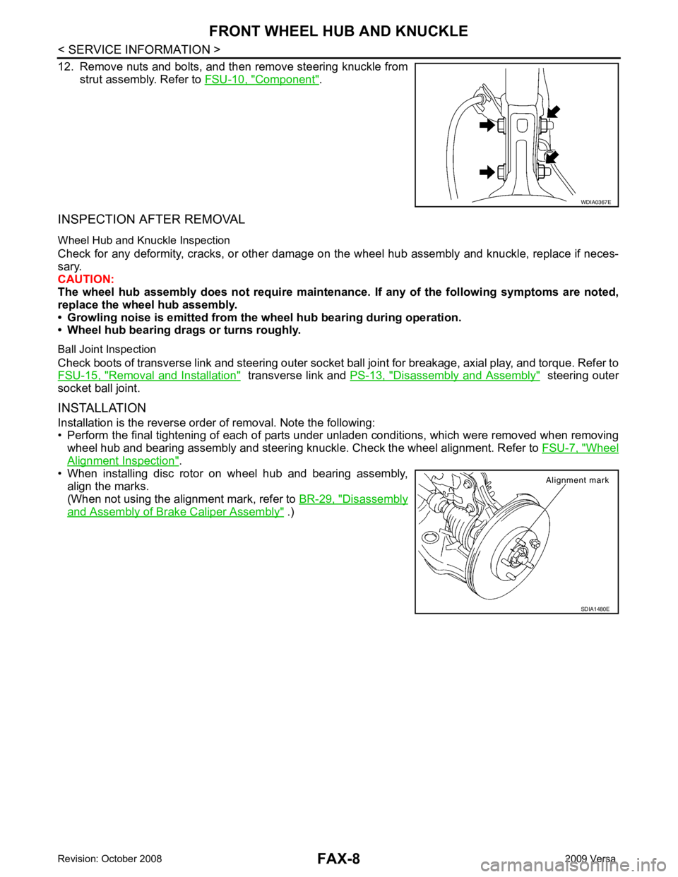
• When installing disc rotor on wheel hub and bearing assembly,
align the marks.
(When not using the alignment mark, refer to BR-29, " Disassembly
and Assembly of Brake Caliper Assembly " .) WDIA0367E
SDIA1480E
Page 3204 of 4331
FAX
N
O P
FRONT DRIVE SHAFT
On-Vehicle Inspection and Service INFOID:0000000004305845
• Check drive shaft mounting point and joint for looseness and other damage.
• Check boot for cracks and other damage.
Replace or repair components as necessary. Refer to FAX-9, " Removal and Installation (Left Side) " ,
FAX-10, " Removal and Installation (Right Side) " ,
FAX-13, " Disassembly and Assembly (Left Side) " or
FAX-18, " Disas-
sembly and Assembly (Right Side) " .
CAUTION:
Replace entire drive shaft assembly when noi se or vibration occur from drive shaft.
Removal and Installation (Left Side) INFOID:0000000004305846
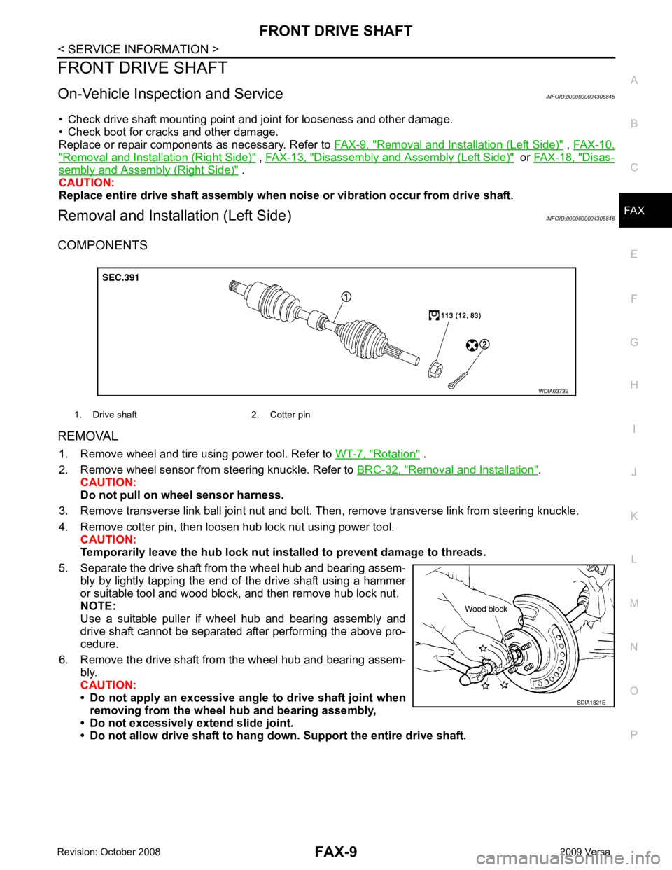
COMPONENTS
REMOVAL 1. Remove wheel and tire using power tool. Refer to WT-7, " Rotation " .
2. Remove wheel sensor from steering knuckle. Refer to BRC-32, " Removal and Installation " .
CAUTION:
Do not pull on wheel sensor harness.
3. Remove transverse link ball joint nut and bolt. Then, remove transverse link from steering knuckle.
4. Remove cotter pin, then loosen hub lock nut using power tool. CAUTION:
Temporarily leave the hub lock nut inst alled to prevent damage to threads.
5. Separate the drive shaft from the wheel hub and bearing assem- bly by lightly tapping the end of the drive shaft using a hammer
or suitable tool and wood block, and then remove hub lock nut.
NOTE:
Use a suitable puller if wheel hub and bearing assembly and
drive shaft cannot be separated after performing the above pro-
cedure.
6. Remove the drive shaft from the wheel hub and bearing assem- bly.
CAUTION:
• Do not apply an excessive angle to drive shaft joint when
removing from the wheel hub and bearing assembly,
• Do not excessively extend slide joint.
• Do not allow drive shaft to hang do wn. Support the entire drive shaft.
1. Drive shaft 2. Cotter pin
Page 3212 of 4331
FRONT DRIVE SHAFT
FAX-17
< SERVICE INFORMATION >
C
E F
G H
I
J
K L
M A
B FAX
N
O P
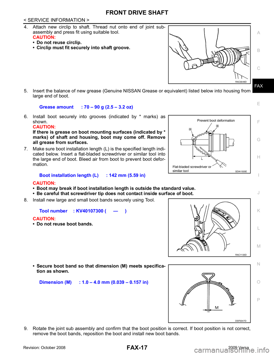
4. Attach new circlip to shaft. Thread nut onto end of joint sub-
assembly and press fit using suitable tool.
CAUTION:
• Do not reuse circlip.
• Circlip must fit securely into shaft groove.
5. Insert the balance of new grease (Genuine NISSAN Grease or equivalent) listed below into housing from
large end of boot.
6. Install boot securely into grooves (indicated by * marks) as shown.
CAUTION:
If there is grease on boot mounting surfaces (indicated by *
marks) of shaft and housing, boot may come off. Remove
all grease from surfaces.
7. Make sure boot installation length (L) is the specified length indi- cated below. Insert a flat-bladed screwdriver or similar tool into
the large end of boot. Bleed air from boot to prevent boot defor-
mation.
CAUTION:
• Boot may break if boot installation le ngth is outside the standard value.
• Be careful that screwdriver tip does not contact inside surface of boot.
8. Install new large and small boot bands securely using Tool.
CAUTION:
• Do not reuse boot bands.
• Secure boot band so that dimension (M) meets specifica- tion as shown.
9. Rotate the joint sub assembly and confirm that the boot position is correct. If boot position is not correct,
remove the boot bands, reposition the boot and install new boot bands. RAC0049D
Grease amount : 70 – 90 g (2.5 – 3.2 oz)
Boot installation length (L) : 142 mm (5.59 in)
Tool number : KV40107300 ( — ) SDIA1505E
RAC1133D
Dimension (M) : 1.0 – 4.0 mm (0.039 – 0.157 in)
DSF0047D
Page 3214 of 4331
FRONT DRIVE SHAFT
FAX-19
< SERVICE INFORMATION >
C
E F
G H
I
J
K L
M A
B FAX
N
O P
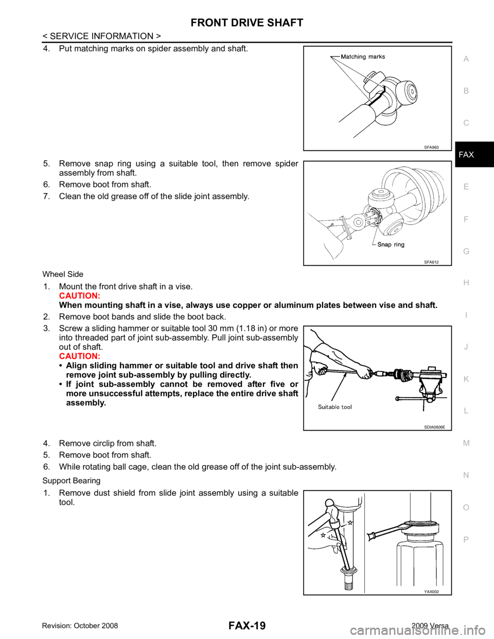
4. Put matching marks on spider assembly and shaft.
5. Remove snap ring using a suitable tool, then remove spider assembly from shaft.
6. Remove boot from shaft.
7. Clean the old grease off of the slide joint assembly.
Wheel Side 1. Mount the front drive shaft in a vise. CAUTION:
When mounting shaft in a vise, always use copper or alum inum plates between vise and shaft.
2. Remove boot bands and slide the boot back.
3. Screw a sliding hammer or suitable tool 30 mm (1.18 in) or more into threaded part of joint sub-assembly. Pull joint sub-assembly
out of shaft.
CAUTION:
• Align sliding hammer or suitab le tool and drive shaft then
remove joint sub-assembly by pulling directly.
• If joint sub-assembly cannot be removed after five or more unsuccessful attempts, replace the entire drive shaft
assembly.
4. Remove circlip from shaft.
5. Remove boot from shaft.
6. While rotating ball cage, clean the old grease off of the joint sub-assembly.
Support Bearing 1. Remove dust shield from slide joint assembly using a suitable tool. SFA963
SFA612
SDIA0606E
YAX002
Page 3216 of 4331
FRONT DRIVE SHAFT
FAX-21
< SERVICE INFORMATION >
C
E F
G H
I
J
K L
M A
B FAX
N
O P
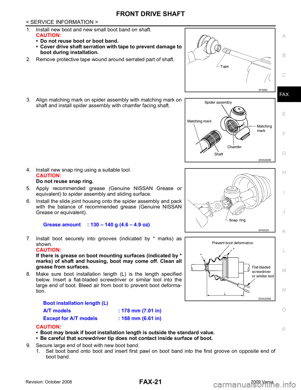
1. Install new boot and new small boot band on shaft.
CAUTION:
• Do not reuse boot or boot band.
• Cover drive shaft serration with tape to prevent damage to
boot during installation.
2. Remove protective tape wound around serrated part of shaft.
3. Align matching mark on spider assembly with matching mark on shaft and install spider assembly with chamfer facing shaft.
4. Install new snap ring using a suitable tool. CAUTION:
Do not reuse snap ring.
5. Apply recommended grease (Genuine NISSAN Grease or equivalent) to spider assembly and sliding surface.
6. Install the slide joint housing onto the spider assembly and pack with the balance of recommended grease (Genuine NISSAN
Grease or equivalent).
7. Install boot securely into grooves (indicated by * marks) as shown.
CAUTION:
If there is grease on boot mounting surfaces (indicated by *
marks) of shaft and housing, boot may come off. Clean all
grease from surfaces.
8. Make sure boot installation length (L) is the length specified below. Insert a flat-bladed screwdriver or similar tool into the
large end of boot. Bleed air from boot to prevent boot deforma-
tion.
CAUTION:
• Boot may break if boot installation le ngth is outside the standard value.
• Be careful that screwdriver tip does not contact inside surface of boot.
9. Secure large end of boot with new boot band. 1. Set boot band onto boot and insert first pawl on boot band into the first groove on opposite end of boot band. SFA800
SDIA2629E
Grease amount : 130 – 140 g (4.6 – 4.9 oz)
SFA023A
Boot installation length (L)
A/T models : 178 mm (7.01 in)
Except for A/T models : 168 mm (6.61 in) SDIA3285E