2009 NISSAN FRONTIER lock
[x] Cancel search: lockPage 111 of 366

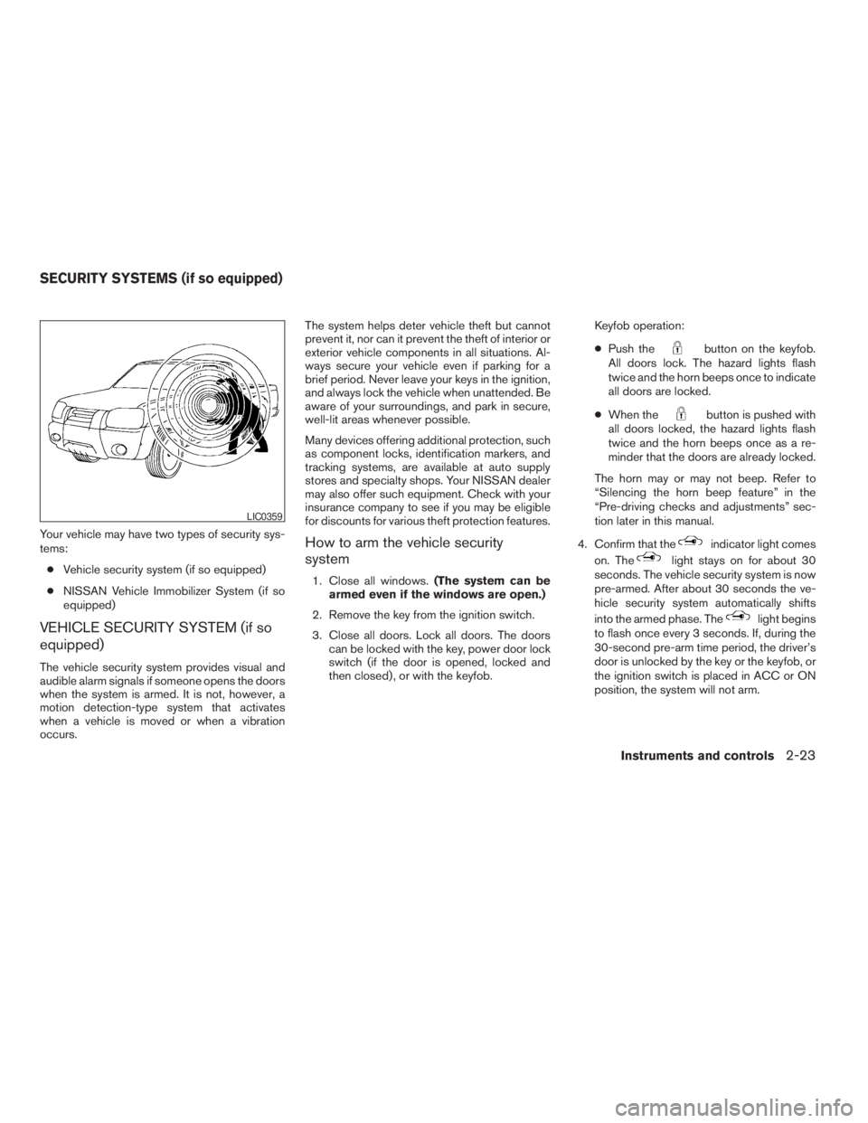
Your vehicle may have two types of security sys-
tems:
cVehicle security system (if so equipped)
cNISSAN Vehicle Immobilizer System (if so
equipped)
VEHICLE SECURITY SYSTEM (if so
equipped)
The vehicle security system provides visual and
audible alarm signals if someone opens the doors
when the system is armed. It is not, however, a
motion detection-type system that activates
when a vehicle is moved or when a vibration
occurs.The system helps deter vehicle theft but cannot
prevent it, nor can it prevent the theft of interior or
exterior vehicle components in all situations. Al-
ways secure your vehicle even if parking for a
brief period. Never leave your keys in the ignition,
and always lock the vehicle when unattended. Be
aware of your surroundings, and park in secure,
well-lit areas whenever possible.
Many devices offering additional protection, such
as component locks, identification markers, and
tracking systems, are available at auto supply
stores and specialty shops. Your NISSAN dealer
may also offer such equipment. Check with your
insurance company to see if you may be eligible
for discounts for various theft protection features.
How to arm the vehicle security
system
1. Close all windows.(The system can be
armed even if the windows are open.)
2. Remove the key from the ignition switch.
3. Close all doors. Lock all doors. The doors
can be locked with the key, power door lock
switch (if the door is opened, locked and
then closed) , or with the keyfob.Keyfob operation:
cPush the
button on the keyfob.
All doors lock. The hazard lights flash
twice and the horn beeps once to indicate
all doors are locked.
cWhen the
button is pushed with
all doors locked, the hazard lights flash
twice and the horn beeps once as a re-
minder that the doors are already locked.
The horn may or may not beep. Refer to
“Silencing the horn beep feature” in the
“Pre-driving checks and adjustments” sec-
tion later in this manual.
4. Confirm that the
indicator light comes
on. The
light stays on for about 30
seconds. The vehicle security system is now
pre-armed. After about 30 seconds the ve-
hicle security system automatically shifts
into the armed phase. The
light begins
to flash once every 3 seconds. If, during the
30-second pre-arm time period, the driver’s
door is unlocked by the key or the keyfob, or
the ignition switch is placed in ACC or ON
position, the system will not arm.
LIC0359
SECURITY SYSTEMS (if so equipped)
Instruments and controls2-23
ZREVIEW COPYÐ2009 08+ Truck/Frontier(fro)
Owners ManualÐUSA_English(nna)
05/27/08Ðdebbie
X
Page 112 of 366

cIf the key is turned slowly when locking
the driver’s door, the system may not
arm. Furthermore, if the key is turned
beyond the vertical position toward the
unlock position to remove the key, the
system may be disarmed when the key
is removed. If the indicator light fails to
glow for 30 seconds, unlock the door
once and lock it again.
cEven when the driver and/or passen-
gers are in the vehicle, the system will
arm with all doors closed and locked
with the ignition switch placed in the
OFF position.
Vehicle security system activation
The vehicle security system will give the following
alarm:
cThe headlights blink and the horn sounds
intermittently.
cThe alarm automatically turns off after ap-
proximately 50 seconds. However, the alarm
reactivates if the vehicle is tampered with
again. The alarm can be shut off by unlocking
the driver’s door with the key or by pressing
the
button on the keyfob.
The alarm is activated by:copening a door without using the key or
keyfob (even if the door is unlocked by using
the inside lock knob or the power door lock
switch) .
How to stop an activated alarm
The alarm stops only by unlocking the driver’s
door with the key or by pressing the
button
on the keyfob.
NISSAN VEHICLE IMMOBILIZER
SYSTEM (if so equipped)
The NISSAN Vehicle Immobilizer System will not
allow the engine to start without the use of a
registered key.
If the engine fails to start using a registered key
(for example, when interference is caused by
another registered key, an automated toll road
device or automatic payment device on the key
ring) , restart the engine using the following pro-
cedures:
1. Leave the ignition switch in the ON position
for approximately 5 seconds.
2. Turn the ignition switch to the OFF or LOCK
position, and wait approximately 10 sec-
onds.
3. Repeat steps 1 and 2.4. Restart the engine while holding the device
(which may have caused the interference)
separate from the registered key.
If the no start condition re-occurs, NISSAN rec-
ommends placing the registered key on a sepa-
rate key ring to avoid interference from other
devices.
Statement related to Section 15 of FCC
Rules for NISSAN Vehicle Immobilizer Sys-
tem (CONT ASSY — IMMOBILIZER, ANT
ASSY — IMMOBILIZER)
This device complies with part 15 of the
FCC Rules and RSS-210 of Industry
Canada. Operation is subject to the follow-
ing two conditions;
(1) This device may not cause harmful in-
terference, and (2) this device must accept
any interference received, including inter-
ference that may cause undesired opera-
tion of the device.
CHANGES OR MODIFICATIONS NOT EX-
PRESSLY APPROVED BY THE PARTY RE-
SPONSIBLE FOR COMPLIANCE COULD
VOID THE USER’S AUTHORITY TO OPER-
ATE THE EQUIPMENT.
2-24Instruments and controls
ZREVIEW COPYÐ2009 08+ Truck/Frontier(fro)
Owners ManualÐUSA_English(nna)
05/27/08Ðdebbie
X
Page 113 of 366

Security indicator light
The security indicator light blinks whenever the
ignition switch is placed in the LOCK, OFF or ACC
position. This function indicates the NISSAN Ve-
hicle Immobilizer System is operational.
If the NISSAN Vehicle Immobilizer System is mal-
functioning, the light will remain on while the
ignition switch is placed in the ON position.
If the light still remains on and/or the en-
gine will not start, see a NISSAN dealer for
NISSAN Vehicle Immobilizer System ser-
vice as soon as possible. Please bring all
registered keys that you have when visiting
your NISSAN dealer for service.
SWITCH OPERATION
The windshield wiper and washer operates when
the ignition switch is placed in the ON position.
Push the lever down to operate the wiper at the
following speed:
s1Intermittent (INT) — intermittent operation
can be adjusted by turning the knob toward
sA(Slower) orsB(Faster) .
s2Low (LO) — continuous low speed operation
s3High (HI) — continuous high speed opera-
tionPush the lever up
s4to have one sweep opera-
tion (MIST) of the wiper.
Pull the lever toward you
s5to operate the
washer. The wiper will also operate several times.
WARNING
In freezing temperatures the washer solu-
tion may freeze on the windshield and
obscure your vision which may lead to an
accident. Warm the windshield with the
defroster before you wash the windshield.
CAUTION
cDo not operate the washer continu-
ously for more than 30 seconds.
cDo not operate the washer if the reser-
voir tank is empty.
cDo not fill the window washer reservoir
tank with washer fluid concentrates at
full strength. Some methyl alcohol
based washer fluid concentrates may
permanently stain the grille if spilled
while filling the window washer reser-
voir tank.LIC0474WIC0854
WINDSHIELD WIPER AND WASHER
SWITCH
Instruments and controls2-25
ZREVIEW COPYÐ2009 08+ Truck/Frontier(fro)
Owners ManualÐUSA_English(nna)
05/27/08Ðdebbie
X
Page 122 of 366

cthe 4WD switch must be in the 4H position
and the vehicle speed must be under 21
mph (35 km/h) , and
cthe hill descent control system switch must
be ON.
The hill descent control system on indicator light
will come on when the system is activated. Also,
the stop/tail lights illuminate while the hill descent
control system applies the brakes to control ve-
hicle speed.
If the accelerator or brake pedal is depressed
while the hill descent control system is on, the
system will stop operating temporarily. As soon
as the accelerator or brake pedal is released, the
hill descent control system begins to function
again if the hill descent control operating condi-
tions are fulfilled.
The hill descent control system on indicator light
blinks if the switch is on and all conditions for
system activation are not met or if the system
becomes disengaged for any reason.
To turn off the hill descent control system, push
the switch to the OFF position.
For additional information, see “Hill descent con-
trol system on indicator light” earlier in this sec-
tion and “Hill descent control system” in the
“Starting and driving” section of this manual.The Electronic Locking Rear Differential (E-Lock)
system can help provide added traction if the
vehicle is stuck or becoming stuck.
To activate the E-Lock system:
cthe 4WD switch must be in the 4LO position
(4-wheel drive vehicles) ,
cthe vehicle must be stopped or moving at 4
mph (7 km/h) or less, and
cthe E-Lock system switch must be turned
ON.When the E-Lock switch is turned ON, the indi-
cator light will flash until the system engages.
However, if all operation conditions listed above
are not met or the system becomes disengaged,
the indicator light will continue to flash.
The Anti-Lock Brake (ABS) system is disabled
and the ABS light illuminates when the E-Lock
system is ON. Also, the Vehicle Dynamic Control
(VDC) system is disabled and the VDC light
illuminates when the E-Lock system is ON.
See “Electronic locking rear differential (E-Lock)
system” in the “Starting and Driving” section for
further explanation and system limitations.
WARNING
cNever leave the E-Lock system ON
when driving on paved or hard-surfaced
roads. Turning the vehicle may result in
the rear wheels slipping and result in an
accident and personal injury. After us-
ing the E-Lock system to free the ve-
hicle, turn the system OFF.
LIC0729
ELECTRONIC LOCKING REAR
DIFFERENTIAL (E-Lock) SYSTEM
SWITCH (if so equipped)
2-34Instruments and controls
ZREVIEW COPYÐ2009 08+ Truck/Frontier(fro)
Owners ManualÐUSA_English(nna)
05/27/08Ðdebbie
X
Page 123 of 366

cUse the E-Lock system only when free-
ing a stuck vehicle. Try the 4LO position
before using the E-Lock system. Never
use the E-Lock system on a slippery
road surface such as snow or ice sur-
face. Using the E-Lock system when
driving in these road conditions may
cause unexpected movement of the ve-
hicle during engine braking, accelerat-
ing or turning, which may result in an
accident and serious personal injury.
CAUTION
cAfter using the E-Lock system, turn the
switch OFF to prevent possible damage
to driveline components from extended
use.
cDo not drive over 12 MPH (20 km/h)
when the system is engaged. Doing so
could result in possible damage to the
driveline.
cDo not turn on the E-lock system while
the tires are spinning. Doing so could
damage drivetrain components.
WARNING
Pay special attention to your surround-
ings when using the clutch interlock
switch. The vehicle will move forward or
backward according to the gear selected.
The clutch interlock (clutch start) switch allows
for starting the engine without depressing the
clutch pedal. This feature helps you restart the
engine if it stops under difficult conditions. (For
example, the engine stops on a steep hill and a
slight movement forward or backward might be
dangerous.)To use the clutch interlock switch:
1. Set the parking brake.
2. Depress the brake pedal with your right foot.
3. Place the shift selector in the 1 position to
move forward, or R to move backward.
4. Place your left foot on the brake pedal and
release the parking brake.
5. Turn the ignition switch to the ON position.
6. Press and release the clutch interlock
switch. The CANCEL light on the switch will
illuminate.
7. Turn the ignition to the START position to
start the engine and, at the same time, de-
press the accelerator pedal with your right
foot. As the vehicle begins to move, take
your left foot off the brake. Once the engine
has started, the clutch interlock switch
CANCEL light shuts off. Do not use the
interlock switch to start the engine under
normal driving conditions.
WIC0817
CLUTCH INTERLOCK (clutch start)
SWITCH (if so equipped)
Instruments and controls2-35
ZREVIEW COPYÐ2009 08+ Truck/Frontier(fro)
Owners ManualÐUSA_English(nna)
05/27/08Ðdebbie
X
Page 127 of 366

UNDER-SEAT STORAGE BINS
WARNING
cProperly secure all cargo with ropes or
straps to help prevent it from sliding or
shifting. In a sudden stop or collision,
unsecured cargo could cause personal
injury.
cThe cargo restrained in the under-seat
storage bins must not exceed the
weight limits listed below or the bins
may not stay secured. In a sudden stop
or collision, the unsecured bins could
cause personal inury.
King cab model: 16 lb (7.25 kg)
Crew cab model
Driver’s side: 16 lb (7.25 kg)
Passenger’s side: 25 lb (11.33 kg)
cIf the under-seat storage bins are re-
moved for any reason, they should be
securely stored to prevent them from
causing injury to passengers or damage
to the vehicle in case of sudden braking
or an accident.cDo not place sharp objects in the under-
seat storage bins. Such objects may
become dangerous projectiles and
cause injury when the vehicle is moving
or if the vehicle is involved in a collision.
To access the under-seat storage bins:
For King cab model, lift up the jump seat. Refer to
“Jump seat” in the “Safety—Seats, seat belts and
supplemental restraint system” section earlier in
this manual.
For Crew cab model, lift up the rear bench seat.
Refer to “Folding the rear bench seat” in the
“Safety—Seats, seat belts and supplemental re-
straint system” section earlier in this manual.
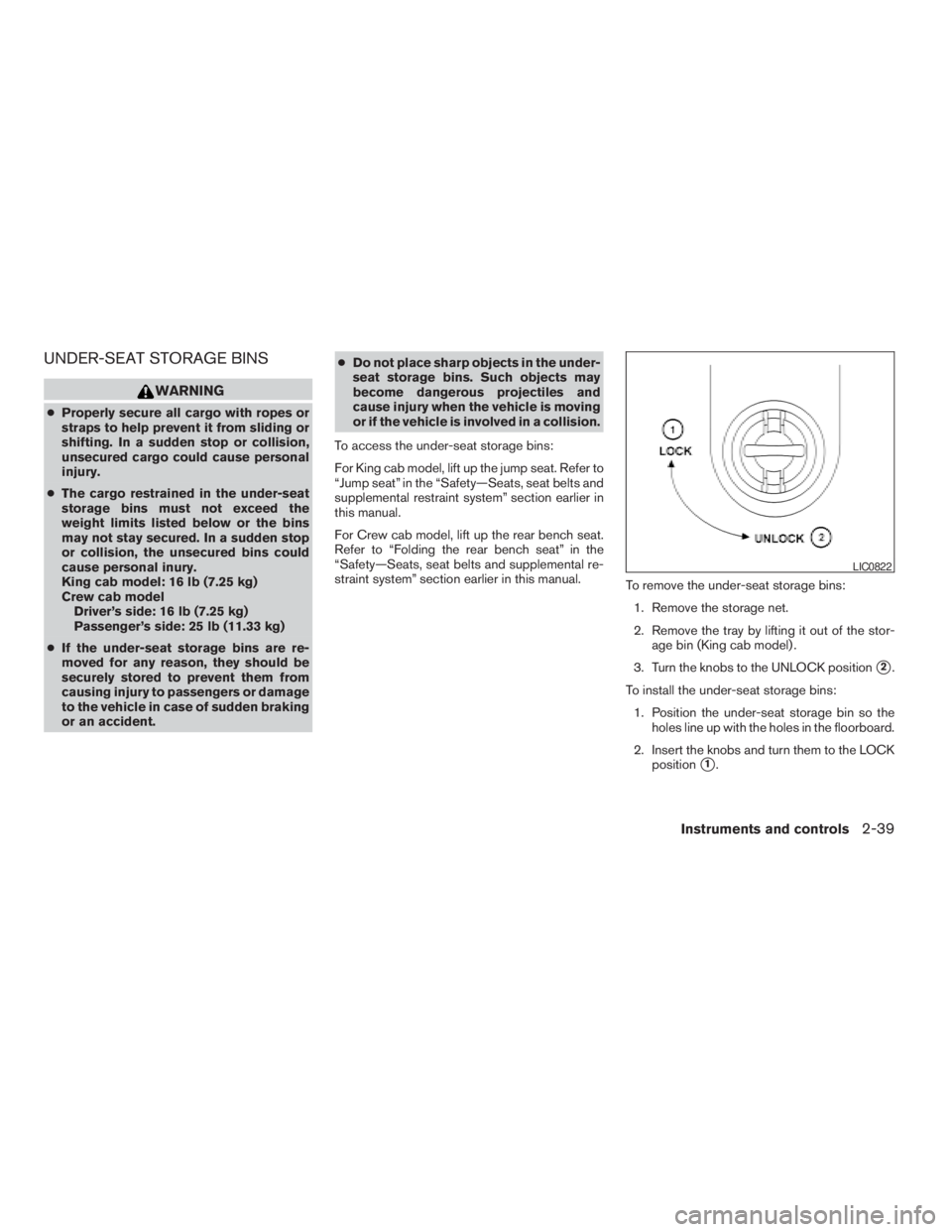
To remove the under-seat storage bins:
1. Remove the storage net.
2. Remove the tray by lifting it out of the stor-
age bin (King cab model) .
3. Turn the knobs to the UNLOCK position
s2.
To install the under-seat storage bins:
1. Position the under-seat storage bin so the
holes line up with the holes in the floorboard.
2. Insert the knobs and turn them to the LOCK
position
s1.
LIC0822
Instruments and controls2-39
ZREVIEW COPYÐ2009 08+ Truck/Frontier(fro)
Owners ManualÐUSA_English(nna)
05/27/08Ðdebbie
X
Page 128 of 366

CONSOLE BOX
Pull up on the levers1to open the console box lid
s2.
GLOVE BOX
To open the top portion of the glove box, push the
latch
sAup and raise the lid.
To open the lower portion of the glove box, pull
the handle
sBdown and lower the lid.
Use the master key to lock or unlock the glove
box. The valet key cannot be used to lock or
unlock the glove box.
WARNING
Keep glove box lid closed while driving to
help prevent injury in an accident or a
sudden stop.
SUNGLASSES HOLDER (if so
equipped)
To open the sunglasses holder, push and release.
WARNING
cKeep the sunglasses holder closed
while driving to prevent an accident.
LIC0766LIC0768WIC0673
2-40Instruments and controls
ZREVIEW COPYÐ2009 08+ Truck/Frontier(fro)
Owners ManualÐUSA_English(nna)
05/27/08Ðdebbie
X
Page 133 of 366

WARNING
cDrive extra carefully when the vehicle is
loaded at or near the cargo carrying
capacity, especially if the significant
portion of that load is carried on the
roof rack.
cHeavy loading of the roof rack has the
potential to affect the vehicle stability
and handling during sudden or abnor-
mal handling maneuvers.
cRoof rack load should be evenly
distributed.
cDo not exceed maximum roof rack load
weight capacity.
cProperly secure all cargo with ropes or
straps to help prevent it from sliding or
shifting. In a sudden stop or collision,
unsecured cargo could cause personal
injury.
CAUTION
Use care when placing or removing items
from the roof rack. If you cannot comfort-
ably lift the items onto the roof rack from
the ground, use a ladder or stool.Always evenly distribute the cargo on the tubular
roof rack.The maximum total load is 125 lb
(56 kg) evenly distributed.Be careful that your
vehicle does not exceed the Gross Vehicle
Weight Rating (GVWR) or the Gross Axle
Weight Ratings (GAWR front and rear) . The
GVWR and GAWR are located on the F.M.V.S.S.
label (located on the driver’s side door jamb
pillar) . For more information regarding GVWR
and GAWR, refer to “Vehicle loading information”
in the “Technical and consumer information” sec-
tion later in this manual.
The front crossbar can be adjusted or removed.
Use the Torxdriver provided in the tool kit to
loosen both crossbar adjusting screws.
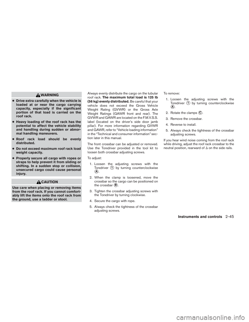
To adjust:
1. Loosen the adjusting screws with the
Torxdriver
s1by turning counterclockwise
sA.
2. When the clamp is loosened, move the
crossbar so the cargo can be positioned on
the crossbar
sB.
3. Tighten the crossbar adjusting screws with
the Torxdriver by turning clockwise.
4. Secure the cargo with rope.
5. Always check the tightness of the crossbar
adjusting screws.To remove:
1. Loosen the adjusting screws with the
Torxdriver
s1by turning counterclockwise
sA.
2. Rotate the clamps
sC.
3. Remove the crossbar.
4. Reverse to install.
5. Always check the tightness of the crossbar
adjusting screws.
If you hear wind noise coming from the roof rack
while driving, adjust the roof rack crossbar to the
neutral position, rearward ofDon the side rails.
Instruments and controls2-45
ZREVIEW COPYÐ2009 08+ Truck/Frontier(fro)
Owners ManualÐUSA_English(nna)
05/27/08Ðdebbie
X