2009 MITSUBISHI ASX fuse
[x] Cancel search: fusePage 4 of 368
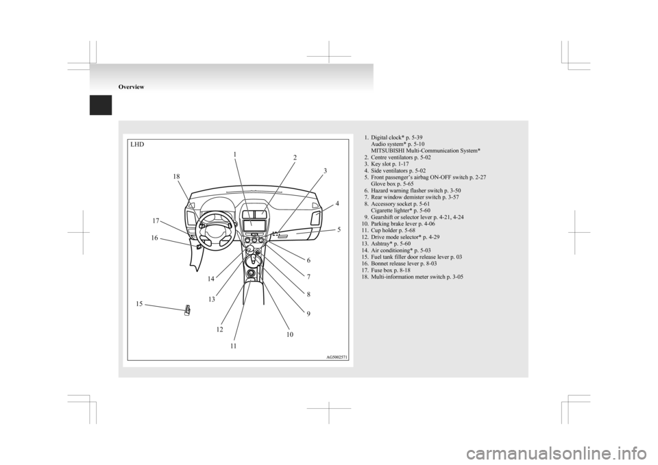
1. Digital clock* p. 5-39
Audio system* p. 5-10
MITSUBISHI Multi-Communication System*
2.
Centre ventilators p. 5-02
3. Key slot p. 1-17
4. Side ventilators p. 5-02
5. Front passenger’s airbag ON-OFF switch p. 2-27 Glove box p. 5-65
6. Hazard warning flasher switch p. 3-50
7. Rear window demister switch p. 3-57
8. Accessory socket p. 5-61 Cigarette lighter* p. 5-60
9. Gearshift or selector lever p. 4-21, 4-24
10. Parking brake lever p. 4-06
11. Cup holder p. 5-68
12. Drive mode selector* p. 4-29
13. Ashtray* p. 5-60
14. Air conditioning* p. 5-03
15. Fuel tank filler door release lever p. 03
16. Bonnet release lever p. 8-03
17. Fuse box p. 8-18
18. Multi-information meter switch p. 3-05 OverviewLHD
12
3
45
6 7
8
9
10
1
1
12
13
14
15 16
17 18
Page 5 of 368
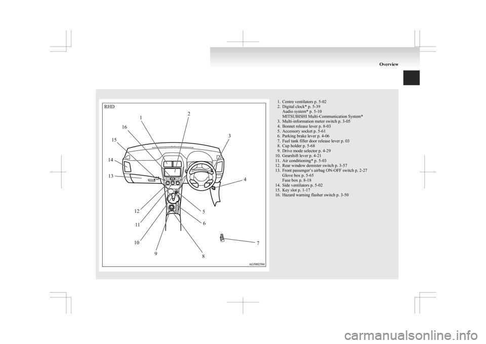
1. Centre ventilators p. 5-02
2.
Digital clock* p. 5-39Audio system* p. 5-10
MITSUBISHI Multi-Communication System*
3. Multi-information meter switch p. 3-05
4. Bonnet release lever p. 8-03
5. Accessory socket p. 5-61
6. Parking brake lever p. 4-06
7. Fuel tank filler door release lever p. 03
8. Cup holder p. 5-68
9. Drive mode selector p. 4-29
10. Gearshift lever p. 4-21
11. Air conditioning* p. 5-03
12. Rear window demister switch p. 3-57
13. Front passenger’s airbag ON-OFF switch p. 2-27 Glove box p. 5-65
Fuse box p. 8-18
14. Side ventilators p. 5-02
15. Key slot p. 1-17
16. Hazard warning flasher switch p. 3-50 OverviewRHD
1 2
3
4
5 6
7
8
9
10 1
1
12
13
14 15
16
Page 19 of 368
Modification/alterations to the
electrical or fuel systems E00200400368
MITSUBISHI MOTORS CORPORATION
has al-
ways manufactured safe, high quality vehicles. In
order to maintain this safety and quality, it is impor-
tant that any accessory that is to be fitted, or any
modifications carried out which involve the electri-
cal or fuel systems, should be carried out in accord-
ance with MITSUBISHI guidelines. CAUTION
l
If
the wires interfere with the vehicle
body or improper installation methods
are used (protective fuses not included,
etc.), electronic devices may be adversely
affected, resulting in a fire or other acci-
dent. Genuine parts
E00200500499
MITSUBISHI MOTORS
has gone to great lengths
to bring you a superbly crafted automobile offering
the highest quality and dependability.
Use MITSUBISHI MOTORS Genuine Parts, de-
signed and manufactured to maintain your
MITSUBISHI MOTORS automobile at top per-
formance. MITSUBISHI MOTORS Genuine Parts
are identified by this mark and are available at all
MITSUBISHI MOTORS Authorized Service
Points. Safety and disposal information
for used engine oil E00200600155 WARNING
l Prolonged
and repeated contact may
cause serious skin disorders, including
dermatitis and cancer.
l Avoid contact with the skin as far as pos-
sible and wash thoroughly after any con-
tact.
l Keep used engine oils out of reach of chil-
dren.
Protect the environment
It
is illegal to pollute drains, water courses and soil.
Use authorized waste collection facilities, includ-
ing civic amenity sites and garages providing facili-
ties for disposal of used oil and used oil filters. If in
doubt, contact your local authority for advice on dis-
posal. General information
05
Page 178 of 368
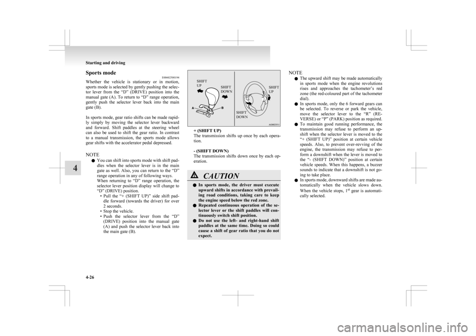
Sports mode
E00602500194
Whether
the vehicle is stationary or in motion,
sports mode is selected by gently pushing the selec-
tor lever from the “D” (DRIVE) position into the
manual gate (A). To return to “D” range operation,
gently push the selector lever back into the main
gate (B).
In sports mode, gear ratio shifts can be made rapid-
ly simply by moving the selector lever backward
and forward. Shift paddles at the steering wheel
can also be used to shift the gear ratio. In contrast
to a manual transmission, the sports mode allows
gear shifts with the accelerator pedal depressed.
NOTE
l You can shift into sports mode with shift pad-
dles when the selector lever is in the main
gate as well. Also, you can return to the “D”
range operation in any of following ways.
When returning to “D” range operation, the
selector lever position display will change to
“D” (DRIVE) position.
• Pull the “+ (SHIFT UP)” side shift pad-dle forward (towards the driver) for over
2 seconds.
• Stop the vehicle.
• Push the selector lever from the “D” (DRIVE) position into the manual gate
(A) and push the selector lever back into
the main gate (B).
SHIFT
UP SHIFT
DOWN SHIFT
UP
SHIFT
DOWN + (SHIFT UP)
The
transmission shifts up once by each opera-
tion.
- (SHIFT DOWN)
The transmission shifts down once by each op-
eration. CAUTION
l
In
sports mode, the driver must execute
upward shifts in accordance with prevail-
ing road conditions, taking care to keep
the engine speed below the red zone.
l Repeated continuous operation of the se-
lector lever or the shift paddles will con-
tinuously switch shift position.
l Do not use the left- and right-hand shift
paddles at the same time. Doing so could
cause a shift of gear ratio that you do not
expect. NOTE
l The
upward shift may be made automatically
in sports mode when the engine revolutions
rises and approaches the tachometer’s red
zone (the red-coloured part of the tachometer
dial).
l In sports mode, only the 6 forward gears can
be selected. To reverse or park the vehicle,
move the selector lever to the “R” (RE-
VERSE) or “P” (PARK) position as required.
l To maintain good running performance, the
transmission may refuse to perform an up-
shift when the selector lever is moved to the
“+ (SHIFT UP)” position at certain vehicle
speeds. Also, to prevent over-revving of the
engine, the transmission may refuse to per-
form a downshift when the lever is moved to
the “- (SHIFT DOWN)” position at certain
vehicle speeds. When this happens, a buzzer
sounds to indicate that a downshift is not go-
ing to take place.
l In sports mode, downward shifts are made au-
tomatically when the vehicle slows down.
When the vehicle stops, 1 st
gear is automati-
cally selected. Starting and driving
4-26
4
Page 250 of 368
WARNING
l Although the Bluetooth ®
2.0 interface al-
lows you to make hands-free calls, if you
choose to use the cellular phone while driv-
ing, you must not allow yourself to be dis-
tracted from the safe operation of your ve-
hicle. Anything, including cellular phone
usage, that distracts you from the safe op-
eration of your vehicle increases your
risk of an accident.
l Refer to and comply with all state and lo-
cal laws in your area regarding cellular
phone usage while driving.
NOTE l If
the ignition switch or the operation mode
is left in ACC, the accessory power will auto-
matically turn off after a certain period of
time and you will no longer be able to use
the Bluetooth ®
2.0 interface. The accessory
power comes on again if the ignition switch
or the engine switch is operated.
Refer to “ACC power auto-cutout function”
on page 4-11.
l The Bluetooth ®
2.0 interface cannot be used
if the Bluetooth ®
device has a flat battery or
the device power is turned off.
l Hands-free calls will not be possible if your
phone does not have service available.
l If you place the Bluetooth ®
device in the lug-
gage compartment, you may not be able to
use the Bluetooth ®
2.0 interface.
l Some Bluetooth ®
devices are not compatible
with the Bluetooth ®
2.0 interface.
Steering control switch ® p. 5-42 Voice recognition function
® p. 5-43
Useful voice commands ® p. 5-43
Speaker enrollment function
® p. 5-45
Connecting the Bluetooth® 2.0 interface and Blue-
tooth® device ® p. 5-46
Operating a music player connected via Blue-
tooth® ® p. 5-48
How to make or receive hands-free
calls ® p. 5-48
Phone book function ® p. 5-50
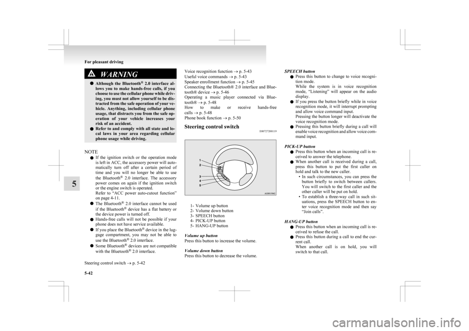
Steering control switch E00727200119 1- Volume up button
2-
Volume down button
3- SPEECH button
4- PICK-UP button
5- HANG-UP button
Volume up button
Press this button to increase the volume.
Volume down button
Press this button to decrease the volume. SPEECH button
l Press
this button to change to voice recogni-
tion mode.
While the system is in voice recognition
mode, “Listening” will appear on the audio
display.
l If you press the button briefly while in voice
recognition mode, it will interrupt prompting
and allow voice command input.
Pressing the button longer will deactivate the
voice recognition mode.
l Pressing this button briefly during a call will
enable voice recognition and allow voice com-
mand input.
PICK-UP button l Press this button when an incoming call is re-
ceived to answer the telephone.
l When another call is received during a call,
press this button to put the first caller on
hold and talk to the new caller.
• In such circumstances, you can press thebutton briefly to switch between callers.
You will switch to the first caller and the
other caller will be put on hold.
• To establish a three-way call in such sit- uations, press the SPEECH button to en-
ter voice recognition mode and then say
“Join calls”.
HANG-UP button l Press this button when an incoming call is re-
ceived to refuse the call.
l Press this button during a call to end the cur-
rent call.
When another call is on hold, you will
switch to that call. For pleasant driving
5-42
5
Page 307 of 368
Service precautions
....................................................................... 8-02
Catalytic converter ........................................................................ 8-02
Bonnet...........................................................................................8-03
Engine oil ......................................................................................8-04
Engine coolant .............................................................................. 8-06
Washer fluid ................................................................................. 8-07
Brake fluid/Clutch fluid* .............................................................. 8-07
Battery .......................................................................................... 8-08
Tyres............................................................................................. 8-11
Parking brake break-in..................................................................
8-15
Wiper blade rubber replacement...................................................8-15
General maintenance .................................................................... 8-17
For cold and snowy weather......................................................... 8-17
Fusible links.................................................................................. 8-18
Fuses............................................................................................. 8-18
Replacement of lamp bulbs .......................................................... 8-23Maintenance
8
Page 323 of 368

General maintenance
E01002700520
Fuel, engine coolant, oil and exhaust
gas leakage
Look
under the body of your vehicle to check for
fuel, engine coolant, oil and exhaust gas leaks. WARNING
l If
you see a suspicious fuel leak or if you
smell fuel, do not operate the vehicle; call
your MITSUBISHI MOTORS Author-
ized Service Point for assistance.
Exterior and interior lamp operation
Operate
the combination lamp switch to check that
all lamps are functioning properly.
If the lamps do not illuminate, the probable cause
is a blown fuse or defective lamp bulb. Check the
fuses first. If there is no blown fuse, check the
lamp bulbs.
For information regarding the inspection and re-
placement of the fuses and the lamp bulbs, refer to
“Fuses” on page 8-18 and “Replacement of lamp
bulbs” on page 8-23.
If the fuses and bulbs are all OK, we recommend
you to have your vehicle checked and repaired.
Meter, gauge and indicator/warning
lamps operation
Start the engine and check the operation of all in-
struments, gauges and indication and warning lamps.
If there is anything wrong, we recommend you to
have your vehicle inspected. Hinges and latches lubrication
Check
all latches and hinges, and, if necessary,
have them lubricated. For cold and snowy weather
E01002800361
Ventilation slots
The
ventilation slots in front of the windscreen
should be kept clear of leaves or brushed clear after
heavy snowfall, so that the operation of the heating
and ventilation systems will not be impaired.
Weatherstripping
To prevent freezing of the weatherstripping on the
doors, bonnet, etc., they should be treated with sili-
cone grease.
Additional equipment
It is a good idea to carry a shovel or a short-han-
dled spade in the vehicle during the winter so that
you can clear away snow if you get stranded. A
small hand-brush for sweeping snow off the vehi-
cle and a plastic scraper for the windscreen and
rear window are also useful. Maintenance
8-17 8
Page 324 of 368
Fusible links
E01002900564
The
fusible links will melt to prevent a fire if a
large current attempts to flow through certain elec-
trical systems.
In case of a melted fusible link, we recommend
you to have your vehicle inspected.
For the fusible links, please refer to “Fuse load ca-
pacity” on page 8-20. WARNING
l Fusible
links must not be replaced by any
other device. Failing to fit the correct fusi-
ble link may result in fire in the vehicle,
property destruction and serious or fatal
injuries at any time. Fuses
E01003002205
Fuse block location
To
prevent damage to the electrical system due to
shortcircuiting or overloading, each individual cir-
cuit is provided with a fuse.
There are fuse blocks in the passenger compart-
ment and in the engine compartment.
Passenger compartment (LHD vehicles)
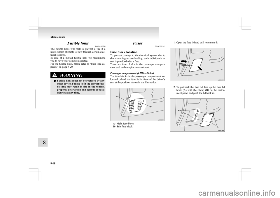
The fuse blocks in the passenger compartment are
located behind the fuse lid in front of the driver’s
seat at the position shown in the illustration. A- Main fuse block
B-
Sub fuse block 1. Open the fuse lid and pull to remove it.
2. To
put back the fuse lid, line up the fuse lid
hook (A) with the clamp (B) on the instru-
ment panel and push the lid back in. Maintenance
8-18
8