2009 MITSUBISHI ASX braking
[x] Cancel search: brakingPage 191 of 368

CAUTION
ard brake system is working. (The stand-
ard
brake system is functioning normal-
ly.) If this happens, we recommend you to
have your vehicle inspected as soon as pos-
sible. • When the ignition switch is turned tothe “ON” position or the operation
mode is put in ON, the warning lamp
does not come on or it remains on and
does not go off.
• The warning lamp comes on while driv- ing
• The warning display appears while driving
If the warning lamp/display illuminate
while driving E00607301295
If only the ABS warning lamp/display illuminate
Avoid
hard braking and high-speed driving. Stop
the vehicle in a safe place.
Restart the engine and check to see whether the
lamp goes out after a few minutes driving; if it then
remains off during driving, there is no problem.
However, if the warning lamp/display do not disap-
pear, or if they come on again when the vehicle is
driven, we recommend you to have the vehicle
checked. If the ABS warning lamp/display and brake warn-
ing lamp/display illuminate at the same time
Warning lamp Warning display type 1
Warning display type 2
The ABS and brake force distribution function may
not
work, so hard braking could make the vehicle
unstable.
Avoid hard braking and high-speed driving. Stop
the vehicle in a safe place and we recommend you
to have it checked. NOTE
l The
ABS warning lamp and brake warning
lamp illuminate at the same time and the warn-
ing displays appear alternately on the infor-
mation screen in the multi-information dis-
play.
After driving on icy roads E00618800150
After driving on snow or icy roads, remove any
snow
and ice which may have accumulated around
the wheels. On vehicles that have an ABS, be care-
ful not to damage the wheel speed sensors (A) or
the cables located at each wheel.
Front
Rear Starting and driving
4-39 4
Page 194 of 368
NOTE
l The
combination of items shown on the dis-
play varies depending on the vehicle model. CAUTION
l
When display/indicator blinks, ASC is
operating,
which means that the road is
slippery or that your vehicle’s wheels are
beginning to slip. If this happens, drive
slower with less accelerator input.
l If the temperature in the braking system
continues to increase due to continuous
brake control on a slippery road surface,
the display/indicator will blink. To pre-
vent
the brake system from overheating,
the brake control of the traction control
function will be temporarily suspended.
The engine control of the traction control
function and normal brake operation will
not be affected. Park your vehicle in a
safe place. When the temperature in the
braking system has come down, the dis-
play/indicator
will be turned off and the
traction control function will start operat-
ing again.
NOTE l The display/indicator may turn on when
you
start the engine. This means that the bat-
tery voltage momentarily dropped when the
engine was started. It does not indicate a mal-
function, provided that the display goes out
immediately. l
When
a compact spare tyre has been put on
your vehicle, the gripping ability of the tyre
will be lower, making it more likely that the display/indicator will blink.
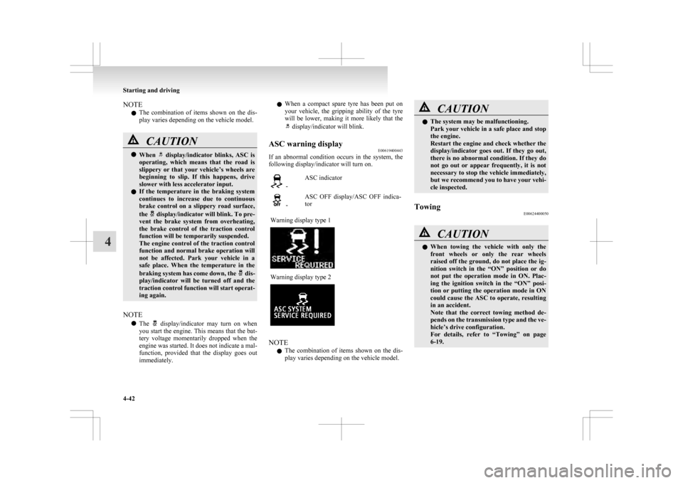
ASC warning display E00619400443
If an abnormal condition occurs in the system, the
following display/indicator will turn on. -
ASC indicator -
ASC OFF display/ASC OFF indica-
tor
Warning display type 1 Warning display type 2
NOTE
l The
combination of items shown on the dis-
play varies depending on the vehicle model. CAUTION
l
The system may be malfunctioning.
Park
your vehicle in a safe place and stop
the engine.
Restart the engine and check whether the
display/indicator goes out. If they go out,
there is no abnormal condition. If they do
not go out or appear frequently, it is not
necessary to stop the vehicle immediately,
but we recommend you to have your vehi-
cle inspected.
Towing E00624400050 CAUTION
l
When
towing the vehicle with only the
front wheels or only the rear wheels
raised off the ground, do not place the ig-
nition switch in the “ON” position or do
not put the operation mode in ON. Plac-
ing the ignition switch in the “ON” posi-
tion or putting the operation mode in ON
could cause the ASC to operate, resulting
in an accident.
Note that the correct towing method de-
pends on the transmission type and the ve-
hicle’s drive configuration.
For details, refer to “Towing” on page
6-19. Starting and driving
4-42
4
Page 198 of 368
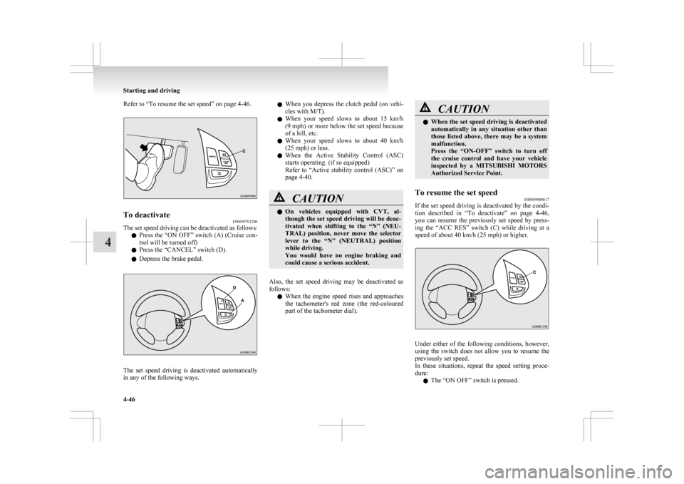
Refer to “To resume the set speed” on page 4-46.
To deactivate
E00609701206
The set speed driving can be deactivated as follows:
l Press
the “ON OFF” switch (A) (Cruise con-
trol will be turned off)
l Press the “CANCEL” switch (D).
l Depress the brake pedal. The set speed driving is deactivated automatically
in any of the following ways. l
When
you depress the clutch pedal (on vehi-
cles with M/T).
l When your speed slows to about 15 km/h
(9 mph) or more below the set speed because
of a hill, etc.
l When your speed slows to about 40 km/h
(25 mph) or less.
l When the Active Stability Control (ASC)
starts operating. (if so equipped)
Refer to “Active stability control (ASC)” on
page 4-40. CAUTION
l
On
vehicles equipped with CVT, al-
though the set speed driving will be deac-
tivated when shifting to the “N” (NEU-
TRAL) position, never move the selector
lever to the “N” (NEUTRAL) position
while driving.
You would have no engine braking and
could cause a serious accident.
Also, the set speed driving may be deactivated as
follows: l When
the engine speed rises and approaches
the tachometer's red zone (the red-coloured
part of the tachometer dial). CAUTION
l
When
the set speed driving is deactivated
automatically in any situation other than
those listed above, there may be a system
malfunction.
Press the “ON-OFF” switch to turn off
the cruise control and have your vehicle
inspected by a MITSUBISHI MOTORS
Authorized Service Point.
To resume the set speed E00609800617
If the set speed driving is deactivated by the condi-
tion
described in “To deactivate” on page 4-46,
you can resume the previously set speed by press-
ing the “ACC RES” switch (C) while driving at a
speed of about 40 km/h (25 mph) or higher. Under either of the following conditions, however,
using
the switch does not allow you to resume the
previously set speed.
In these situations, repeat the speed setting proce-
dure:
l The “ON OFF” switch is pressed. Starting and driving
4-46
4
Page 205 of 368
NOTE
l We
recommend you to use a genuine
MITSUBISHI roof carrier, since the brackets
to be used have a special shape.
For details, we recommend you to consult a
MITSUBISHI MOTORS Authorized Service
Point.
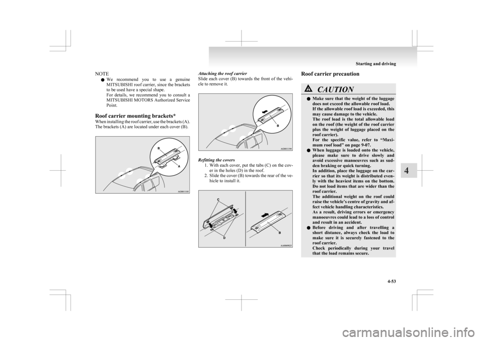
Roof carrier mounting brackets*
When installing the roof carrier, use the brackets (A).
The brackets (A) are located under each cover (B). Attaching the roof carrier
Slide
each cover (B) towards the front of the vehi-
cle to remove it. Refitting the covers
1. With
each cover, put the tabs (C) on the cov-
er in the holes (D) in the roof.
2. Slide the cover (B) towards the rear of the ve- hicle to install it. Roof carrier precaution
CAUTION
l
Make
sure that the weight of the luggage
does not exceed the allowable roof load.
If the allowable roof load is exceeded, this
may cause damage to the vehicle.
The roof load is the total allowable load
on the roof (the weight of the roof carrier
plus the weight of luggage placed on the
roof carrier).
For the specific value, refer to “Maxi-
mum roof load” on page 9-07.
l When luggage is loaded onto the vehicle,
please make sure to drive slowly and
avoid excessive manoeuvres such as sud-
den braking or quick turning.
In addition, place the luggage on the car-
rier so that its weight is distributed even-
ly with the heaviest items on the bottom.
Do not load items that are wider than the
roof carrier.
The additional weight on the roof could
raise the vehicle’s centre of gravity and af-
fect vehicle handling characteristics.
As a result, driving errors or emergency
manoeuvres could lead to a loss of control
and result in an accident.
l Before driving and after travelling a
short distance, always check the load to
make sure it is securely fastened to the
roof carrier.
Check periodically during your travel
that the load remains secure. Starting and driving
4-53 4
Page 207 of 368

1
830.5 mm
2 461 mm
3 68.5 mm
4 75 mm
5 310 mm
6 13.5 mm
7 66.5 mm
8 50 mm
9 52 mm
10 464 mm
(at kerb weight condi- tion)
370 mm to 384 mm (at laden condition)
11 447 mm
12 487 mm
13 495 mm
14 525.5 mmNOTE
l The
values under item 12 can be varied de-
pending on the loading condition of cargo or
luggage.
Operating hints l To prevent the clutch from slipping (Vehicle
with a M/T only), do not rev the engine more
than is required when starting off. l
Be
sure that the driving speed does not ex-
ceed 100 km/h (62 mph) for trailer operation.
It is also recommended that you obey the lo-
cal regulations in case driving speed with a
trailer is limited to less than 100 km/h
(62 mph).
l To prevent shocks from the overrun brake, de-
press the brake pedal lightly at first and then
more strongly.
l To make full use of engine braking, change
to a lower shift point before descending a
slope.
Additional precautions for vehicles equipped with
a CVT
It is recommended the “D” position on slopes or at
low speed.
Use the sports mode in mountainous areas in order
to make better use of engine braking and to assist
the brake system.
However, be sure that the speed does not exceed
the maximum speed limit for the selected shift posi-
tion.
Overheating
This will normally occur as a result of some me-
chanical failure. If your vehicle should overheat,
stop and check for a loose or broken water pump/
alternator drive belt, a blocked radiator air intake
or a low coolant level. If these items are satisfacto-
ry the overheating could be caused by a number of
mechanical causes that would have to be checked
at a competent service centre. CAUTION
l
If the engine overheats, please refer to the
“Engine
overheating” section of “For
emergencies” prior to taking any correc-
tive action.
l On vehicles equipped with CVT, if the warning display is showing, the tempera-
ture of the CVT fluid is high.
Read
the reference page and take the re-
quired measures.
Refer to “When a malfunction occurs in
the CVT” on page 4-27. Starting and driving
4-55 4
Page 277 of 368
Bottle holder
E00718200328CAUTION
l
Do not drink beverages while driving.
This is distracting and could cause an ac-
cident.
l Drinks could be spilled by the vibration
and jolts while driving. If the spilt drink
is very hot, you could be burnt.
There are bottle holders located on the front doors. NOTE
l Tightly
close the cap on drink bottles before
storing them.
l Some bottles may be too big or the wrong
shape to fit in the holder. Rear shelf panel*
E00715400114 CAUTION
l
Do
not place luggage or other items on
the rear shelf panel. Any items on the
rear shelf panel would obstruct your rear-
ward view, and they could fly forward
and cause injuries or other mishap in the
event of hard braking.
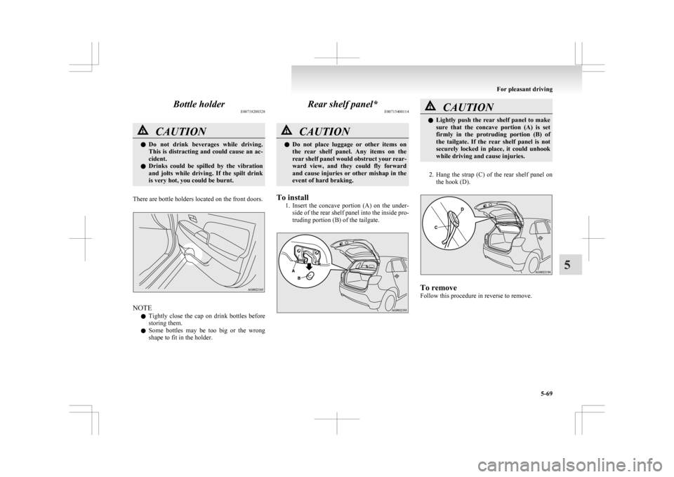
To install 1. Insert
the concave portion (A) on the under-
side of the rear shelf panel into the inside pro-
truding portion (B) of the tailgate. CAUTION
l
Lightly
push the rear shelf panel to make
sure that the concave portion (A) is set
firmly in the protruding portion (B) of
the tailgate. If the rear shelf panel is not
securely locked in place, it could unhook
while driving and cause injuries.
2. Hang
the strap (C) of the rear shelf panel on the hook (D). To remove
Follow this procedure in reverse to remove. For pleasant driving
5-69 5
Page 278 of 368
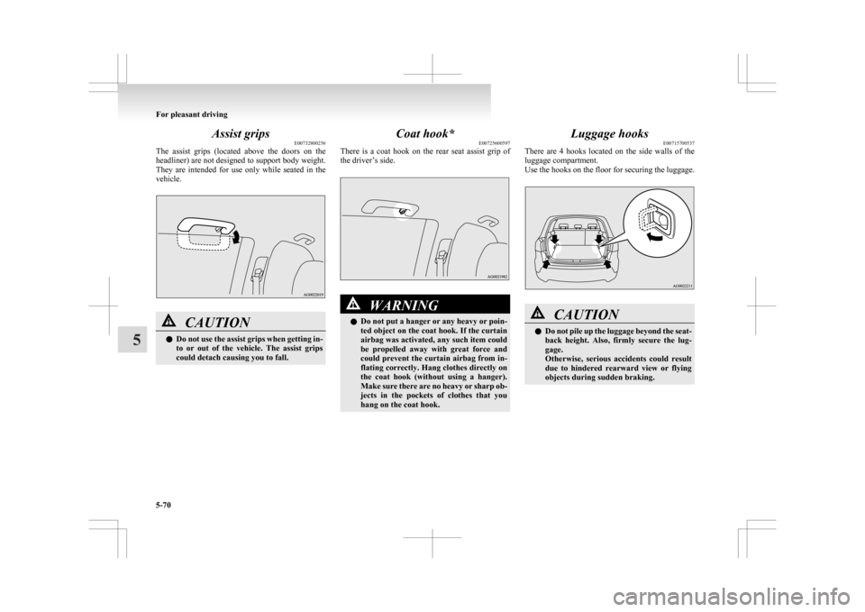
Assist grips
E00732800256
The
assist grips (located above the doors on the
headliner) are not designed to support body weight.
They are intended for use only while seated in the
vehicle. CAUTION
l
Do
not use the assist grips when getting in-
to or out of the vehicle. The assist grips
could detach causing you to fall. Coat hook*
E00725600597
There
is a coat hook on the rear seat assist grip of
the driver’s side. WARNING
l Do
not put a hanger or any heavy or poin-
ted object on the coat hook. If the curtain
airbag was activated, any such item could
be propelled away with great force and
could prevent the curtain airbag from in-
flating correctly. Hang clothes directly on
the coat hook (without using a hanger).
Make sure there are no heavy or sharp ob-
jects in the pockets of clothes that you
hang on the coat hook. Luggage hooks
E00715700537
There
are 4 hooks located on the side walls of the
luggage compartment.
Use the hooks on the floor for securing the luggage. CAUTION
l
Do
not pile up the luggage beyond the seat-
back height. Also, firmly secure the lug-
gage.
Otherwise, serious accidents could result
due to hindered rearward view or flying
objects during sudden braking. For pleasant driving
5-70
5
Page 291 of 368
Spare wheel information*
E00803600497
Check
the air pressure of the spare tyre frequently
and make sure it is ready for emergency use at any
time.
Maintaining the spare wheel at the highest speci-
fied air pressure will ensure that it can always be
used under any conditions (city/high-speed driving,
varying load weight, etc.).
The spare wheel is stored beneath the luggage floor
board of the luggage compartment. CAUTION
l
The
pressure should be periodically
checked and maintained at the specified
pressure while the tyre is stowed.
Driving with an insufficient tyre pressure
can lead to an accident. If you have no
choice but to drive with an insufficient
tyre pressure, keep your speed down and
inflate the tyre to the correct pressure as
soon as possible. (Refer to “Tyre inflation
pressures” on page 8-12.)
l When the tread wear indicators appear,
the tyre must be replaced.
Refer to “Wheel condition” on page 8-13.
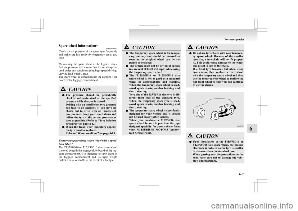
Temporary spare wheel (spare wheel with a speed
limit label)*
The T155/90D16
or T125/90D16 size spare wheel
is stored beneath the luggage floor board of the lug-
gage compartment. It is designed to save space in
the luggage compartment and its light weight
makes it easy to handle in the event of a flat tyre. CAUTION
l
The
temporary spare wheel is for tempo-
rary use only and should be removed as
soon as the original wheel can be re-
paired or replaced.
l The vehicle must not be driven at speeds
in excess of 80 km/h (50 mph) while using
the temporary spare wheel.
l The T155/90D16 or T125/90D16 size
spare wheel is not as good as a standard
wheel in controllability and stability.
When the temporary spare wheel is used,
avoid quick starts, sudden braking and
sharp steering.
Tyre size of the 215/65R16 size tyre is dif-
ferent from that of the standard tyre.
When the temporary spare tyre is used,
avoid quick starts, sudden braking and
sharp steering.
l The temporary spare wheel is specifically
designed for your vehicle and it should
not be used on any other vehicle.
When you purchase a 215/65R16 size
spare wheel, be sure to purchase the type
designed specially for your vehicle from
your MITSUBISHI MOTORS Author-
ized Service Point. CAUTION
l
Do not use tyre chains with your tempora-
ry spare wheel. Because of the smaller
tyre size, a tyre chain will not fit proper-
ly. This could cause damage to the wheel
and result in loss of the chain.
If a front tyre becomes flat when using
tyre chains, first replace a rear wheel
with the temporary spare wheel and then
use the removed rear wheel to replace the
flat front wheel so that you can continue
to use the chains. CAUTION
l
Upon
installation of the T155/90D16 or
T125/90D16 size spare wheel, the ground
clearance is reduced as the tyre is smaller
in diameter than the standard tyre.
When passing over the projections on the
road, take care not to damage the vehi-
cle’s undercarriage. For emergencies
6-13 6