2009 MITSUBISHI ASX fuel type
[x] Cancel search: fuel typePage 167 of 368

Fuel injection amount learning proc-
ess (diesel-powered vehicles)
E00627900043
To
keep exhaust emissions and engine noise low,
the engine very occasionally performs a learning
process for the fuel injection amount.
The engine sounds slightly different from usual
while the learning process is taking place. The
change in the engine sound does not indicate a fault. Diesel particulate filter (DPF)*
E00619800199
The
diesel particulate filter (DPF) is a device that
captures most of the particulate matter (PM) in the
exhaust emissions of the diesel engine. The DPF au-
tomatically burns away trapped PM during vehicle
operation. Under certain driving conditions, howev-
er, the DPF is not able to burn away all of the trap-
ped PM and, as a result, an excessive amount of
PM accumulates inside it. WARNING
l The DPF reaches very high temperatures.
Do
not park your vehicle in areas where
combustible materials such as dry grass
or leaves can come in contact with a hot
exhaust system since a fire could occur. CAUTION
l
Do
not use any type of fuel or engine oil
that is not specified for your vehicle. Al-
so, do not use any moisture-removing
agent or other fuel additive. Such substan-
ces could have a detrimental effect on the
DPF.
Refer to “Fuel selection” on page 02 and
“Engine oil” on page 8-04.
NOTE l To
minimize the likelihood of excessive ac-
cumulation of PM, try to avoid driving for
long periods at low speeds and repeatedly
driving short distances. l
The
engine sounds slightly different than usu-
al while the DPF automatically burns away
trapped PM. The change in the engine sound
does not indicate a fault.
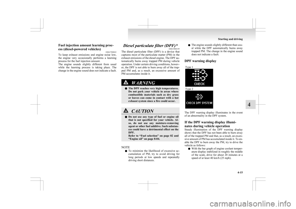
DPF warning display Type 1 Type 2
The DPF warning display illuminates in the event
of an abnormality in the DPF system.
If the DPF warning display illumi-
nates during vehicle operation
Steady
illumination of the DPF warning display
shows that the DPF has not been able to burn away
all of the trapped PM and that, as a result, an exces-
sive amount of PM has accumulated inside it. To en-
able the DPF to burn away the PM, try to drive the
vehicle as follows:
l With the bar graph of engine coolant temper-
ature display stabilized in roughly the middle
of the scale, drive for about 20 minutes at a
speed of at least 40 km/h (25 mph). Starting and driving
4-15 4
Page 181 of 368

Electronically controlled 4WD
system* E00604900280
The
electronically controlled 4WD system is a 4-
wheel drive system that allows one of three drive
modes to be selected with a dial, in accordance
with the driving conditions.
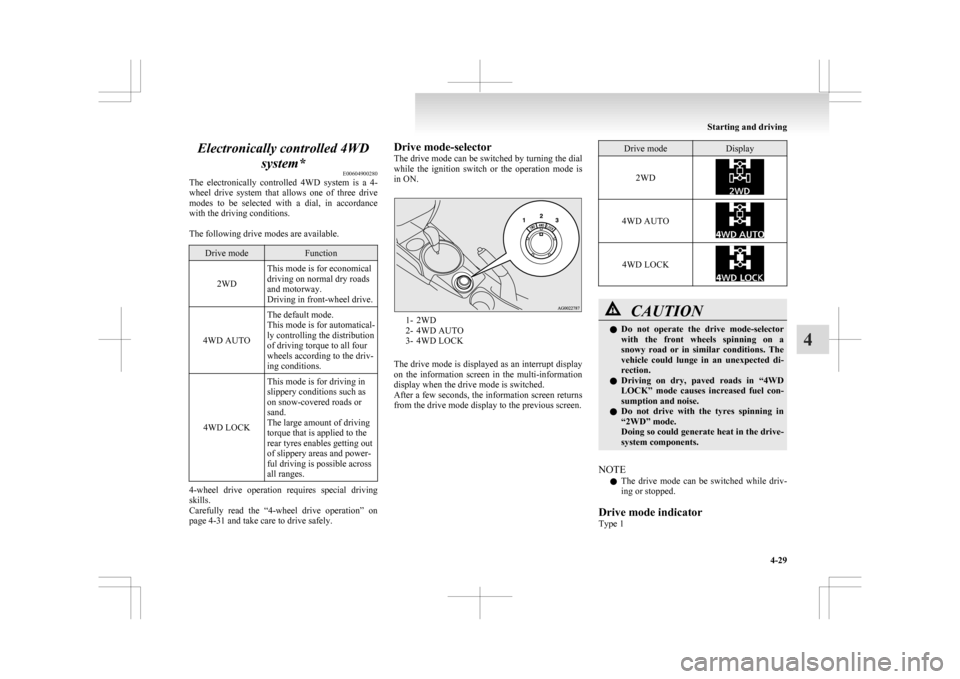
The following drive modes are available. Drive mode Function
2WD This mode is for economical
driving on normal dry roads
and motorway.
Driving in front-wheel drive.
4WD AUTO The default mode.
This mode is for automatical-
ly controlling the distribution
of driving torque to all four
wheels according to the driv-
ing conditions.
4WD LOCK This mode is for driving in
slippery conditions such as
on snow-covered roads or
sand.
The large amount of driving
torque that is applied to the
rear tyres enables getting out
of slippery areas and power-
ful driving is possible across
all ranges.4-wheel drive operation requires special driving
skills.
Carefully
read the “4-wheel drive operation” on
page 4-31 and take care to drive safely. Drive mode-selector
The
drive mode can be switched by turning the dial
while the ignition switch or the operation mode is
in ON. 1- 2WD
2-
4WD AUTO
3- 4WD LOCK
The drive mode is displayed as an interrupt display
on the information screen in the multi-information
display when the drive mode is switched.
After a few seconds, the information screen returns
from the drive mode display to the previous screen. Drive mode Display
2WD 4WD AUTO
4WD LOCK
CAUTION
l
Do not operate the drive mode-selector
with the front wheels spinning on a
snowy road or in similar conditions. The
vehicle could lunge in an unexpected di-
rection.
l Driving on dry, paved roads in “4WD
LOCK” mode causes increased fuel con-
sumption and noise.
l Do not drive with the tyres spinning in
“2WD” mode.
Doing so could generate heat in the drive-
system components.
NOTE l The
drive mode can be switched while driv-
ing or stopped.
Drive mode indicator
Type 1 Starting and driving
4-29 4
Page 308 of 368

Service precautions
E01000100878
Adequate
care of your vehicle at regular intervals
serves to preserve the value and appearance as long
as possible.
Maintenance items as described in this owner’s man-
ual can be performed by the owner.
We recommend you to have the periodic inspection
and maintenance performed by a MITSUBISHI
MOTORS Authorized Service Point or another spe-
cialist.
In the event a malfunction or a problem is discov-
ered, we recommend you to have it checked and re-
paired. This section contains information on inspec-
tion maintenance procedures that you can do your-
self. Follow the instructions and cautions for each
of the various procedures. WARNING
l When
checking or servicing the inside of
the engine compartment, make sure the
engine is switched off and has had a
chance to cool down.
l If it is necessary to do work in the engine
compartment with the engine running, be
especially careful that your clothing, hair,
etc., does not become caught by the fan,
drive belts, or other moving parts.
l The fan may turn on automatically even
if the engine is not running. Turn the igni-
tion switch to the “LOCK” position or
put the operation mode in OFF to be safe
while you work in the engine compart-
ment. WARNING
l Do
not smoke, cause sparks or allow open
flames around fuel or battery. The fumes
are flammable.
l Be extremely cautious when working
around the battery. It contains poisonous
and corrosive sulphuric acid.
l Do not get under your vehicle with just
the body jack supporting it. Always use
automotive jack stands.
l Improper handling of components and
materials used in the vehicle can endan-
ger your personal safety. We recommend
you to consult a specialist for necessary in-
formation. Catalytic converter
E01000200765
The
exhaust gas scavenging devices used with the
catalytic converter are extremely efficient for the re-
duction of noxious gases. The catalytic converter is
installed in the exhaust system.
It is important to keep the engine properly tuned to
ensure proper catalyst operation and prevent possi-
ble catalyst damage. WARNING
l As
with any vehicle, do not park or oper-
ate this vehicle in areas where combusti-
ble materials such as dry grass or leaves
can come in contact with a hot exhaust
since a fire could occur.
l Paint should not be applied to the catalyt-
ic converter.
NOTE l Use
fuel of the type recommended in “Fuel
selection” on page 02. Maintenance
8-02
8
Page 328 of 368

No. Symbol Electrical system Capaci-
ties
17 Head-
lamp low
beam
(right) Dis-
charge 20 A
18 Head-
lamp low
beam (left) Halogen 10 A
19 Head-
lamp low
beam
(right) Halogen 10 A
20 ENG/POWER 10 A
21 Ignition coil 10 A
22 ENG/POWER 20 A
Fuel line heater 25 A
23 Fuel pump 15 A
24 Starter 30 A*
25 — ——
26 Anti-lock brake
system 40 A*
27 Anti-lock brake
system 30 A* No. Symbol Electrical system Capaci-
ties
28 Air conditioning
condenser fan mo- tor 30 A*
29 Radiator fan motor 40 A*
30 IOD IOD 30 A
31 Audio system amp 30 A
32 Diesel 30 A
33 — Spare fuse 10 A
34 — Spare fuse 15 A
35 — Spare fuse 20 A *: Fusible link
l Some
fuses may not be installed on your ve-
hicle, depending on the vehicle model or spec-
ifications.
l The table above shows the main equipment
corresponding to each fuse.
The fuse box does not contain spare 7.5 A, 25 A or
30 A fuses. If one of these fuses burns out, substi-
tute with the following fuse.
7.5 A: 10 A spare fuse
25 A: 20 A spare fuse
30 A: 30 A audio system amp fuse
When using a substitute fuse, replace with a fuse of
the correct capacity as soon as possible. Identification of fuse Capacity Colour
7.5 A Brown
10 A Red
15 A Blue
20 A Yellow
25 A Natural (White)
30 A Green (fuse type)/
Pink (fusible link type)
40 A Green (fusible link type) Fuse replacement
E01007800630
1. Before replacing a fuse, always turn off the
electrical circuit concerned and turn the igni-
tion switch to the “LOCK” position or put
the operation mode in OFF.
2. Remove the fuse puller (A) from the inside of the fuse box in the engine compartment. 3. Referring
to the fuse load capacity table,
check the fuse pertaining to the problem. Maintenance
8-22
8