Page 248 of 368

(Refer to “Function setup mode” on page
5-16.) NOTE
l Although
“PHONE” appears on the display,
the PHONE function is inoperative.
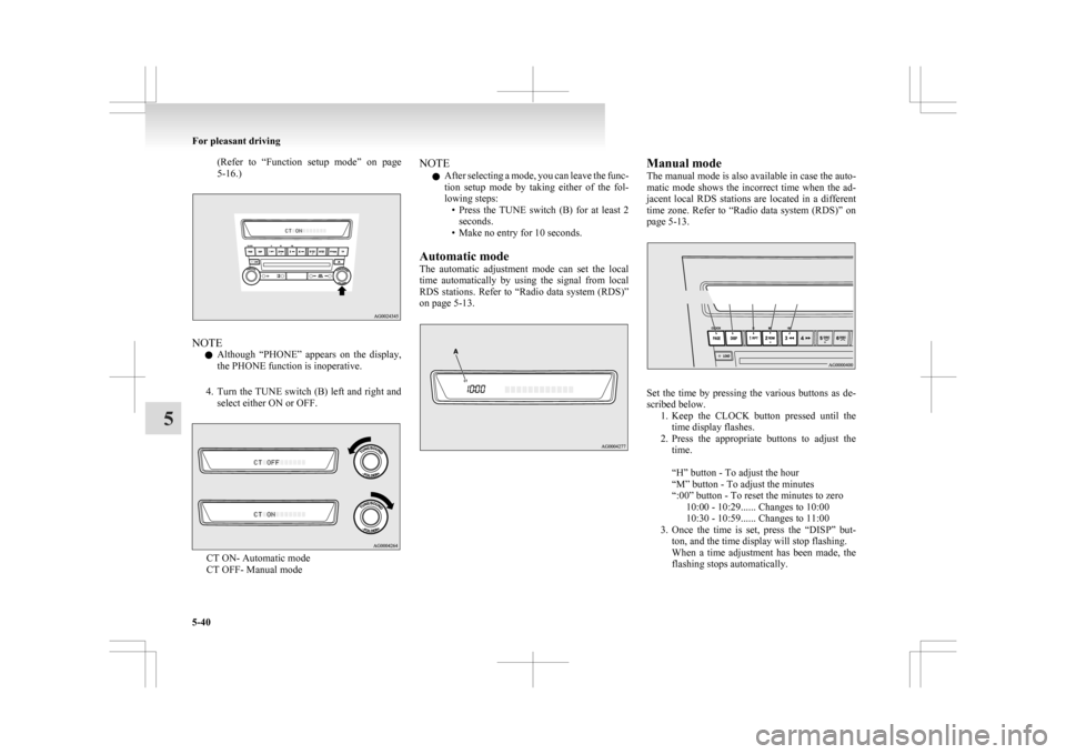
4. Turn the TUNE switch (B) left and right and select either ON or OFF. CT ON- Automatic mode
CT OFF- Manual mode NOTE
l After
selecting a mode, you can leave the func-
tion setup mode by taking either of the fol-
lowing steps: • Press the TUNE switch (B) for at least 2seconds.
• Make no entry for 10 seconds.
Automatic mode
The automatic adjustment mode can set the local
time automatically by using the signal from local
RDS stations. Refer to “Radio data system (RDS)”
on page 5-13. Manual mode
The
manual mode is also available in case the auto-
matic mode shows the incorrect time when the ad-
jacent local RDS stations are located in a different
time zone. Refer to “Radio data system (RDS)” on
page 5-13. Set the time by pressing the various buttons as de-
scribed below.
1. Keep
the CLOCK button pressed until the
time display flashes.
2. Press the appropriate buttons to adjust the time.
“H” button - To adjust the hour
“M” button - To adjust the minutes
“:00” button - To reset the minutes to zero 10:00 - 10:29...... Changes to 10:00
10:30 - 10:59...... Changes to 11:00
3. Once the time is set, press the “DISP” but- ton, and the time display will stop flashing.
When a time adjustment has been made, the
flashing stops automatically. For pleasant driving
5-40
5
Page 249 of 368

NOTE
l If
the battery cables are disconnected during
repairs or for any other reason, reset the
clock to the correct time after they are recon-
nected.
l The digital clock does not have a second dis-
play. When the “minute” display is adjusted
and reset to zero, the clock begins at zero sec-
onds for the selected minute. Link System*
E00764500012
The
Link System takes overall control of the devi-
ces connected via the USB input terminal or the
Bluetooth ®
2.0 interface allowing the connected de-
vices to be operated by using the switches in the ve-
hicle or voice commands.
See the following section for details on how to op-
erate.
Refer to “Bluetooth ®
2.0 interface” on page 5-41.
Refer to “USB input terminal” on page 5-57.
Refer to “To play tracks from USB device” on
page 5-22.
Refer to “To play tracks from a Bluetooth ®
device”
on page 5-30.
Refer to “To use the external audio input function”
on page .
Bluetooth ®
is a registered trademark of BLUE-
TOOTH SIG, INC.
Link System End User Licence Agree-
ment E00764600013
You have acquired a device that includes software
licensed
by MITSUBISHI MOTORS CORPORA-
TION from JOHNSON CONTROLS Inc (the auto-
motive experience business unit), and their subse-
quent 3 rd
party suppliers. For a complete list of
these 3 rd
party products and their end user licence
agreements, please go to the following website.
http://www.jciblueconnect.com/faq.taf Bluetooth
®
2.0 interface*
E00726000370
The Bluetooth ®
2.0 interface allows for making/re-
ceiving hands-free calls in the vehicle using a Blue-
tooth ®
compatible cellular phone based on the wire-
less communication technology commonly known
as Bluetooth ®
. It also allows the user to play mu-
sic, saved in a Bluetooth ®
music player, from the
vehicle’s speakers.
The system is equipped with a voice recognition
function, which allows you to make hands-free
calls by simple switch operations and voice com-
mand operations using a defined voice tree.
The Bluetooth ®
2.0 interface can be used when the
ignition switch or the operation mode is in ON or
ACC.
Before you can use the Bluetooth ®
2.0 interface,
you must pair the Bluetooth ®
device and Blue-
tooth ®
2.0 interface. Refer to “Connecting the Blue-
tooth® 2.0 interface and Bluetooth® device” on
page 5-46.
Bluetooth ®
is a registered trademark of BLUE-
TOOTH SIG, INC. For pleasant driving
5-41 5
Page 286 of 368

l
Use the tyre sealant only at ambient tempera-
tures of -30 °C to + 60 °C.
l Effect an emergency repair without pulling
out the object (nail, screw, etc.) that is stuck
in the tyre.
l Do not use the tyre sealant if the tyre has
been damaged by being driven when insuffi-
ciently inflated (e.g. bumps, cuts, cracks etc.
on the tyre).
l Allow any tyre sealant seeping out of the
hole to dry, then pull off like a film.
l Wipe tyre sealant off the paintwork immedi-
ately with a damp cloth.
l Allow any tyre sealant in a damaged tyre to
dry out and dispose of it together with the tyre.
l Immediately change out of any clothes conta-
minated with the tyre sealant.
Before repairing a tyre, first stop your vehicle in a
safe, flat location. 1. Park the vehicle on level and stable ground.
2. Set the parking brake firmly.
3. On vehicles with M/T, stop the engine andmove the gearshift lever to the “R” (Reverse)
position.
On vehicles with CVT, move the selector lev-
er to the “P” (PARK) position and stop the en-
gine.
4. Turn on the hazard warning flashers and set up a warning triangle, flashing signal lamp,
etc., at an adequate distance from the vehi-
cle, and have all your passengers leave the ve-
hicle.
5. Take out the tyre sealant bottle and the com- pressor.
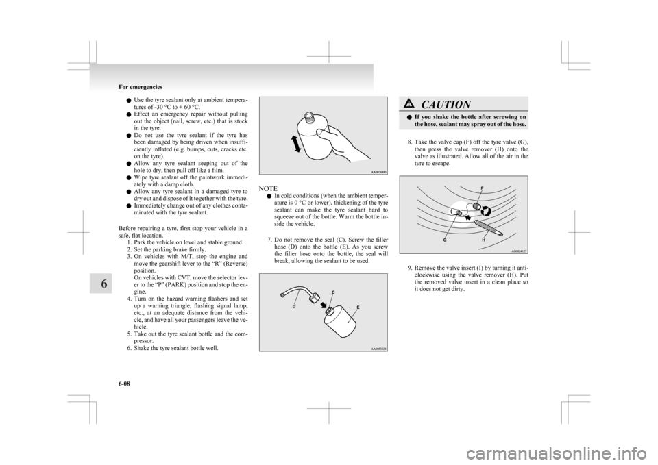
6. Shake the tyre sealant bottle well. NOTE
l In
cold conditions (when the ambient temper-
ature is 0 °C or lower), thickening of the tyre
sealant can make the tyre sealant hard to
squeeze out of the bottle. Warm the bottle in-
side the vehicle.
7. Do not remove the seal (C). Screw the filler hose (D) onto the bottle (E). As you screw
the filler hose onto the bottle, the seal will
break, allowing the sealant to be used. CAUTION
l
If
you shake the bottle after screwing on
the hose, sealant may spray out of the hose.
8. Take
the valve cap (F) off the tyre valve (G), then press the valve remover (H) onto the
valve as illustrated. Allow all of the air in the
tyre to escape. 9. Remove the valve insert (I) by turning it anti-
clockwise
using the valve remover (H). Put
the removed valve insert in a clean place so
it does not get dirty. For emergencies
6-08
6
Page 292 of 368

CAUTION
l
Do not install more than one temporary
spare wheel at the same time.
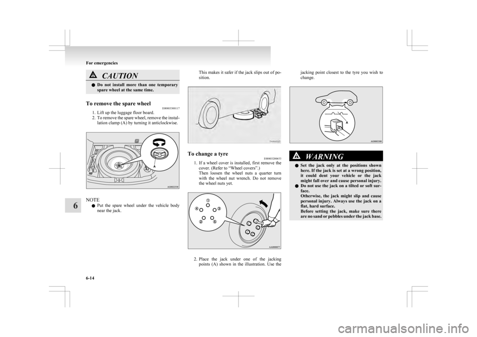
To remove the spare wheel E00803300117
1. Lift up the luggage floor board.
2. To
remove the spare wheel, remove the instal-
lation clamp (A) by turning it anticlockwise. NOTE
l Put
the spare wheel under the vehicle body
near the jack. This makes it safer if the jack slips out of po-
sition.
To change a tyre
E00803200653
1. If
a wheel cover is installed, first remove the
cover. (Refer to “Wheel covers”.)
Then loosen the wheel nuts a quarter turn
with the wheel nut wrench. Do not remove
the wheel nuts yet. 2. Place
the jack under one of the jacking
points (A) shown in the illustration. Use the jacking point closest to the tyre you wish to
change.
WARNING
l Set
the jack only at the positions shown
here. If the jack is set at a wrong position,
it could dent your vehicle or the jack
might fall over and cause personal injury.
l Do not use the jack on a tilted or soft sur-
face.
Otherwise, the jack might slip and cause
personal injury. Always use the jack on a
flat, hard surface.
Before setting the jack, make sure there
are no sand or pebbles under the jack base. For emergencies
6-14
6