2009 MERCEDES-BENZ GL SUV fuse chart
[x] Cancel search: fuse chartPage 12 of 309

Frequencies
Garage door opener .......................298
Telephone ...................................... 285
Front airbag ......................................... 38
Front-passenger airbag ....................... 38
Fuel ..................................................... 287
Diesel ............................................ 173
Loss ............................................... 241
Petrol ............................................. 173
Fuel consumption
Notes ............................................. 288
Fuel filler flap
Emergency release ........................251
Opening/closing ........................... 172
Fuel filter
Display message ............................ 221
Fuel gauge ............................................ 25
Fuel level Calling up the range (on-board
computer) ...................................... 111
Display ............................................. 25
Fuel line
Malfunction ................................... .241
Fuel tank
Defect ............................................ 241
Fuse allocation chart ........................280
Fuse box Dashboard ..................................... 281
Engine compartment .....................281
Luggage compartment ...................281
Fuses .................................................. 280G
Garage door Opening/closing (with the remote
control) .......................................... 166
Garage door opener ..........................165
Clearing the memory .....................166
Frequencies ................................... 298
Programming the remote control ...165
Gear indicator ...................................... 93
Genuine Mercedes-Benz parts .........284
Glove compartment ..........................152
Gradient-climbing capability (max-
imum) ................................................. 191 H
Handbrake Display message ............................ 221
Headlamp cleaning system ..............178
Headlamps Cleaning ......................................... 203
Cleaning system .............................. 83
Misting up ...................................... 245
Headlamps delayed switch-off
see Exterior lighting delayed switch-off
Head restraints
Adjusting (front) ............................... 65
Adjusting (rear) ................................ 68
Luxury .............................................. 66
NECK-PRO ....................................... 40
Removing (rear) ............................... 69
Resetting triggered NECK-PRO
head restraints .............................. 252
Resetting triggered NECK-PRO
luxury head restraints ....................252
Heating
see Air conditioning
High-pressure cleaners ....................202
Hill start assist .................................... 90
HomeLink ®
see Garage door opener I
Immobiliser .......................................... 54
Indicator and warning lamp Automatic child seat recognition
(malfunction) ................................. 234
Brakes (red) ........................... 235, 236
Engine diagnostics .........................237
ESP ®
.............................................. 235
PASSENGER AIRBAG OFF ........43, 234
Reserve fuel ................................... 239
Seat belt ........................................ 238
SRS .......................................... 35, 236
Thermotronic (malfunction) ...........234
Indicator and warning lamps ...........235
Indicator lamp see Indicator and warning lamp .....235
Instrument cluster .............................. 96
On-board computer .......................103 Index
9 X164_AKB; 2; 3, en-GB
wobuchh,
Version: 2.11.8.1
2009-03-31T14:14:58+02:00 - Seite 9Dateiname: 6515431202_buchblock.pdf; erzeugt am 01. Apr 2009 00:16:29; WK
Page 212 of 309

Observe the legal requirements in all coun-
tries concerned.
The fire extinguisher is located underneath
the front of the driver's seat. X
Pull tab :upwards.
X Remove fire extinguisher ;. Vehicle tool kit, TIREFIT, jack and
"Minispare" emergency spare
wheel*
The vehicle tool kit, TIREFIT, jack and
"Minispare" emergency spare wheel are in the
stowage space under the luggage compart-
ment floor. G
Risk of injury
The jack is designed only to raise and hold the
vehicle for a short time while a wheel is being
changed.
You must use axle stands if you are carrying
out work on the vehicle.
Make sure that the jack is placed on a firm,
non-slip, level surface. Do not use wooden
blocks or similar objects as a jack underlay.
Otherwise, the jack will not be able to achieve
its load-bearing capacity due to the restricted
height.
Do not start the engine at any time while a
wheel is being changed. Do not lie under the vehicle when it is being
supported by the jack. If you do not raise the
vehicle as described, it could slip off the jack
(e.g. if the engine is started or if a door or the
tailgate is opened or closed) and you could be
seriously injured.
i When using the jack, you should also
observe the safety notes in the "Flat tyre"
section (Y page 262).
X Open the luggage compartment floor
(Y page 208).
Vehicles with a TIREFIT kit/exterior
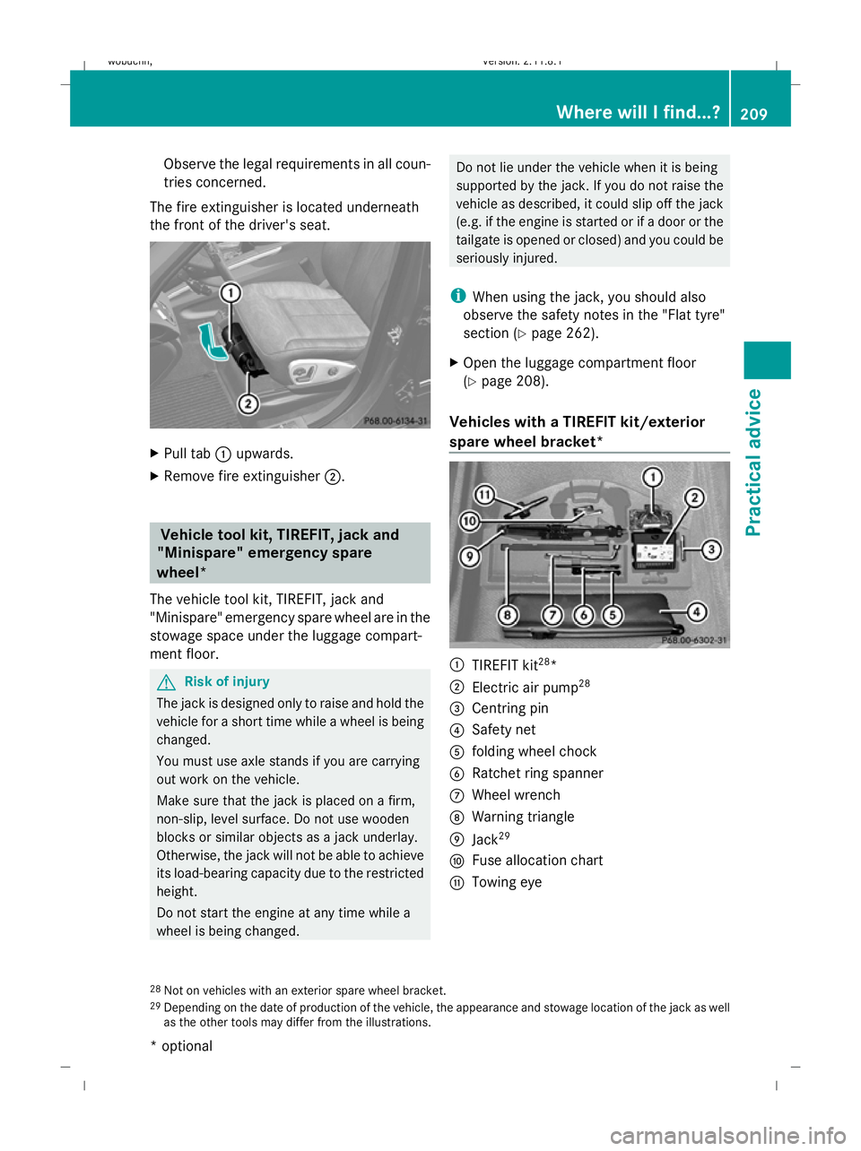
spare wheel bracket* :
TIREFIT kit 28
*
; Electric air pump 28
= Centring pin
? Safety net
A folding wheel chock
B Ratchet ring spanner
C Wheel wrench
D Warning triangle
E Jack 29
F Fuse allocation chart
G Towing eye
28 Not on vehicles with an exterior spare wheel bracket.
29 Depending on the date of production of the vehicle, the appearance and stowage location of the jack as well
as the other tools may differ from the illustrations. Where will I find...?
209Practical advice
* optional
X164_AKB; 2; 3, en-GB
wobuchh,
Version: 2.11.8.1 2009-03-31T14:14:58+02:00 - Seite 209 Z
Dateiname: 6515431202_buchblock.pdf; erzeugt am 01. Apr 2009 00:17:56; WK
Page 214 of 309

A
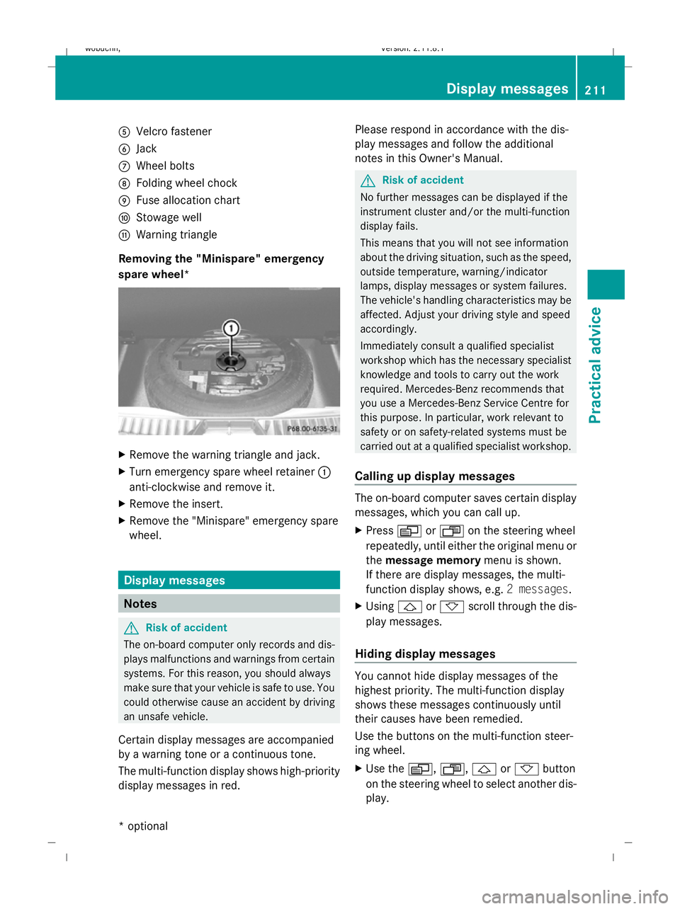
Velcro fastener
B Jack
C Wheel bolts
D Folding wheel chock
E Fuse allocation chart
F Stowage well
G Warning triangle
Removing the "Minispare" emergency
spare wheel* X
Remove the warning triangle and jack.
X Turn emergency spare wheel retainer :
anti-clockwise and remove it.
X Remove the insert.
X Remove the "Minispare" emergency spare
wheel. Display messages
Notes
G
Risk of accident
The on-board computer only records and dis-
plays malfunctions and warnings from certain
systems. For this reason, you should always
make sure that your vehicle is safe to use. You
could otherwise cause an accident by driving
an unsafe vehicle.
Certain display messages are accompanied
by a warning tone or a continuous tone.
The multi-function display shows high-priority
display messages in red. Please respond in accordance with the dis-
play messages and follow the additional
notes in this Owner's Manual. G
Risk of accident
No further messages can be displayed if the
instrument cluster and/or the multi-function
display fails.
This means that you will not see information
about the driving situation, such as the speed,
outside temperature, warning/indicator
lamps, display messages or system failures.
The vehicle's handling characteristics may be
affected. Adjust your driving style and speed
accordingly.
Immediately consult a qualified specialist
workshop which has the necessary specialist
knowledge and tools to carry out the work
required. Mercedes-Benz recommends that
you use a Mercedes-Benz Service Centre for
this purpose. In particular, work relevant to
safety or on safety-related systems must be
carried out at a qualified specialist workshop.
Calling up display messages The on-board computer saves certain display
messages, which you can call up.
X
Press VorU on the steering wheel
repeatedly, until either the original menu or
the message memory menu is shown.
If there are display messages, the multi-
function display shows, e.g. 2 messages.
X Using &or* scroll through the dis-
play messages.
Hiding display messages You cannot hide display messages of the
highest priority. The multi-function display
shows these messages continuously until
their causes have been remedied.
Use the buttons on the multi-function steer-
ing wheel.
X
Use the V,U,&or* button
on the steering wheel to select another dis-
play. Display messages
211Practical advice
* optional
X164_AKB; 2; 3, en-GB
wobuchh,
Version: 2.11.8.1 2009-03-31T14:14:58+02:00 - Seite 211 Z
Dateiname: 6515431202_buchblock.pdf; erzeugt am 01. Apr 2009 00:17:58; WK
Page 283 of 309

Towing in the event of malfunctions
In the event of damage to the transfer
case Have the propeller shafts between the axles
and the transfer case removed.
Have the vehicle towed with the front axle
raised.
In the event of damage to the front axle
Have the propeller shaft between the rear
axle and the transfer case removed.
Have the vehicle towed with the front axle
raised.
In the event of damage to the rear axle Have the propeller shaft between the front
axle and the transfer case removed.
Have the vehicle towed with the rear axle
raised.
! New bolts must always be used when the
propeller shafts are refitted. The specified
tightening torques must be observed.
i Consult a Mercedes-Benz Service Centre.
In the event of damage to the electrical
system If the battery is defective, the automatic
transmission will be locked in position P. To
shift the automatic transmission to neutral,
you must supply power to the vehicle’s elec-
trical system in the same way as jump-start-
ing (Y page 276).
Have the vehicle transported on a transporter
or trailer. Fuses
Notes on changing fuses
The fuses in your vehicle serve to close down
faulty circuits. If a fuse blows, all the compo- nents on the circuit and their functions will
fail.
Blown fuses must be replaced with fuses of
the same rating, which you can recognise by
the colour and value. The fuse ratings are lis-
ted in the fuse allocation chart. A Mercedes-
Benz Service Centre will be happy to advise
you. G
Risk of fire
Only use fuses that have been approved for
Mercedes-Benz vehicles and which have the
required fuse rating for the systems con-
cerned. Do not attempt to repair or bridge
faulty fuses. A circuit overload could other-
wise cause a fire. Have the cause traced and
rectified at a qualified specialist workshop,
e.g. a Mercedes-Benz Service Centre.
If the newly inserted fuse also blows, have the
cause traced and rectified at a qualified spe-
cialist workshop, e.g. a Mercedes-Benz
Service Centre.
! Only use fuses that have been approved
for Mercedes-Benz vehicles and which
have the correct fuse rating for the system
concerned. Otherwise, components or sys-
tems could be damaged.
The fuses are located in various fuse boxes:
R dashboard fuse box on the front-passenger
side
R fuse box in the engine compartment on the
right-hand side of the vehicle
R fuse box in the luggage compartment on
the right-hand side of the vehicle
Fuse allocation chart The fuse allocation chart is located with the
vehicle tool kit (Y
page 209) in the stowage
compartment under the luggage compart-
ment floor. 280
FusesPractical advice
X164_AKB; 2; 3, en-GB
wobuchh
,V ersion: 2.11.8.1
2009-03-31T14:14:58+02:00 - Seite 280
Dateiname: 6515431202_buchblock.pdf; erzeugt am 01. Apr 2009 00:18:20; WK