Page 62 of 309

Individual settings
You can change the setting of the locking
system in such a way that only the driver's
door and the fuel filler flap are unlocked. This
could be useful if you frequently travel on your
own.
X To change the setting: press the%
and & buttons simultaneously for
approximately six seconds until the battery
check lamp flashes twice.
The key now functions as follows:
X To unlock the driver's door: press the
% button once.
X To unlock centrally: press the%but-
ton twice.
X To lock centrally: press the&button.
The KEYLESS GO* function is changed as fol-
lows:
X To unlock the driver's door: touch the
inner surface of the door handle on the
driver's door.
X To unlock centrally: touch the inner sur-
face of the door handle on the front-
passenger door or the rear door.
X To lock centrally: press locking but-
ton :on one of the door handles.
Restoring the factory settings X
Press the %and& buttons simulta-
neously for approximately six seconds until
the battery check lamp flashes twice.
Additional information R
Convenience opening (Y page 87)
R Convenience closing (Y page 87)
R Opening and closing in an emergency
(Y page 250) Opening the doors from the inside
You can open a door from the inside even if it
has been locked, unless the child-proof locks
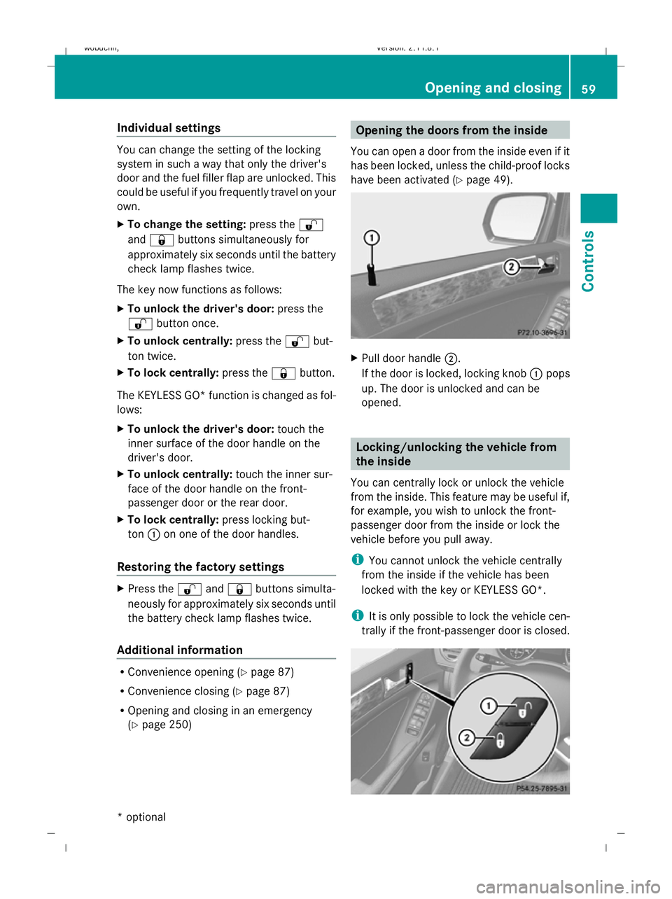
have been activated ( Ypage 49). X
Pull door handle ;.
If the door is locked, locking knob :pops
up. The door is unlocked and can be
opened. Locking/unlocking the vehicle from
the inside
You can centrally lock or unlock the vehicle
from the inside. This feature may be useful if,
for example, you wish to unlock the front-
passenger door from the inside or lock the
vehicle before you pull away.
i You cannot unlock the vehicle centrally
from the inside if the vehicle has been
locked with the key or KEYLESS GO*.
i It is only possible to lock the vehicle cen-
trally if the front-passenger door is closed. Opening and closing
59Controls
* optional
X164_AKB; 2; 3, en-GB
wobuchh,
Version: 2.11.8.1 2009-03-31T14:14:58+02:00 - Seite 59 Z
Dateiname: 6515431202_buchblock.pdf; erzeugt am 01. Apr 2009 00:16:52; WK
Page 202 of 309

G
Risk of accident
Do not carry the ball coupling in the vehicle
interior if it is not secured.
Otherwise, you and others could be injured by
the ball coupling being thrown around if you:
R brake sharply
R change direction suddenly
R are involved in an accident
Information on cleaning and care of the trailer
coupling can be found at (Y page 203).Trailer power supply
When it leaves the factory, your vehicle's
trailer socket outlet is equipped with a per-
manent power supply and a power supply that
is switched on via the ignition lock.
The permanent power supply is supplied via
trailer socket pin 9.
The power supply that is switched on via the
ignition lock is supplied via trailer socket
pin 10.
! You can connect consumers with a power
rating of up to 240 W to the permanent
power supply and up to 180 W to the power
supply that is switched on via the ignition
lock.
You must not charge a trailer battery using
the power supply.
The trailer's turn signal lamps are only guar-
anteed to function when bulbs are used.
You can obtain further information about
installing the trailer electrics from a qualified
specialist workshop, e.g. a Mercedes-Benz
Service Centre.
X To switch the connected power supply
on or off: turn the key in the ignition lock
to position 2or 0, respectively. Trailer with 7-pin connector
If your trailer has a 7-pin connector, you can
connect it to the 13-pin socket on the ball
coupling using an adapter or, if necessary, an
adapter cable. Both of these can be obtained
at a qualified specialist workshop, e.g. at a
Mercedes-Benz Service Centre.
Fitting the adapter X
Open the socket cover.
X Insert connector with lug :into
groove ;on the socket and turn the con-
nector clockwise to the stop.
X Make the cover engage.
X If you are using an adapter cable, secure
the cable to the trailer with cable ties.
! Make sure that there is sufficient cable
play so that the cable cannot become
detached when cornering. Service
ASSYST PLUS service interval display
The ASSYST PLUS service interval display
informs you of the next service due date.
The service due date is shown in the multi-
function display, for example:
Service A in .. days
Service A in .. km
Service A due now
The letter indicates how much time the work-
shop will require to carry out the service work. Service
199Operation
X164_AKB; 2; 3, en-GB
wobuchh, Version: 2.11.8.1 2009-03-31T14:14:58+02:00 - Seite 199 Z
Dateiname: 6515431202_buchblock.pdf; erzeugt am 01. Apr 2009 00:17:52; WK
Page 234 of 309

Display messages
Possible causes/consequences and
X
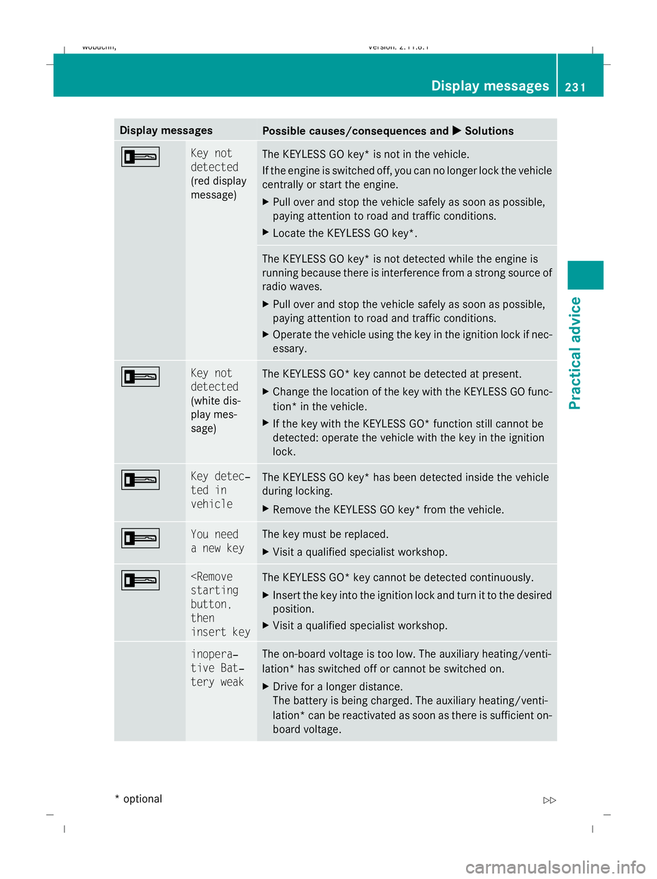
X Solutions + Key not
detected
(red display
message)
The KEYLESS GO key* is not in the vehicle.
If the engine is switched off, you can no longer lock the vehicle
centrally or start the engine.
X
Pull over and stop the vehicle safely as soon as possible,
paying attention to road and traffic conditions.
X Locate the KEYLESS GO key*. The KEYLESS GO key* is not detected while the engine is
running because there is interference from a strong source of
radio waves.
X Pull over and stop the vehicle safely as soon as possible,
paying attention to road and traffic conditions.
X Operate the vehicle using the key in the ignition lock if nec-
essary. + Key not
detected
(white dis-
play mes-
sage)
The KEYLESS GO* key cannot be detected at present.
X
Change the location of the key with the KEYLESS GO func-
tion* in the vehicle.
X If the key with the KEYLESS GO* function still cannot be
detected: operate the vehicle with the key in the ignition
lock. + Key detec‐
ted in
vehicle
The KEYLESS GO key* has been detected inside the vehicle
during locking.
X
Remove the KEYLESS GO key* from the vehicle. + You need
a new key The key must be replaced.
X
Visit a qualified specialist workshop. +
starting
button,
then
insert key
The KEYLESS GO* key cannot be detected continuously.
X
Insert the key into the ignition lock and turn it to the desired
position.
X Visit a qualified specialist workshop. & inopera‐
tive Bat‐
tery weak The on-board voltage is too low. The auxiliary heating/venti-
lation* has switched off or cannot be switched on.
X
Drive for a longer distance.
The battery is being charged. The auxiliary heating/venti-
lation *can be reactivated as soon as there is sufficient on-
board voltage. Display messages
231Practical advice
* optional
X164_AKB; 2; 3, en-GB
wobuchh,
Version: 2.11.8.1 2009-03-31T14:14:58+02:00 - Seite 231 Z
Dateiname: 6515431202_buchblock.pdf; erzeugt am 01. Apr 2009 00:18:01; WK