2009 MERCEDES-BENZ E-CLASS SALOON service indicator
[x] Cancel search: service indicatorPage 215 of 373
i
The garage door opener is only available
for certain countries. Observe the legal
requirements in all countries concerned.
The HomeLink ®
garage door opener is
compatible with most European garage and
gate opener drives. More information on
HomeLink ®
and/or compatible products is
available from:
R any Mercedes-Benz Service Centre
R the HomeLink ®
hotline
(0) 08000 466 354 65 (free of charge) or
+49 (0) 6838 907-277 (charges apply)
R the Internet: www.homelink.com G
Risk of accident
Only press the transmitter button on the inte-
grated remote control if there are no persons
or objects present within the sweep of the
garage door. Persons could otherwise be
injured as the door moves.
Programming the remote control i
You will achieve the best results by insert-
ing new batteries in the garage door's
remote control before programming it.
X Erase the memory of the integrated remote
control (Y page 213) before programming
it for the first time.
X Turn the key to position 2in the ignition
lock. X
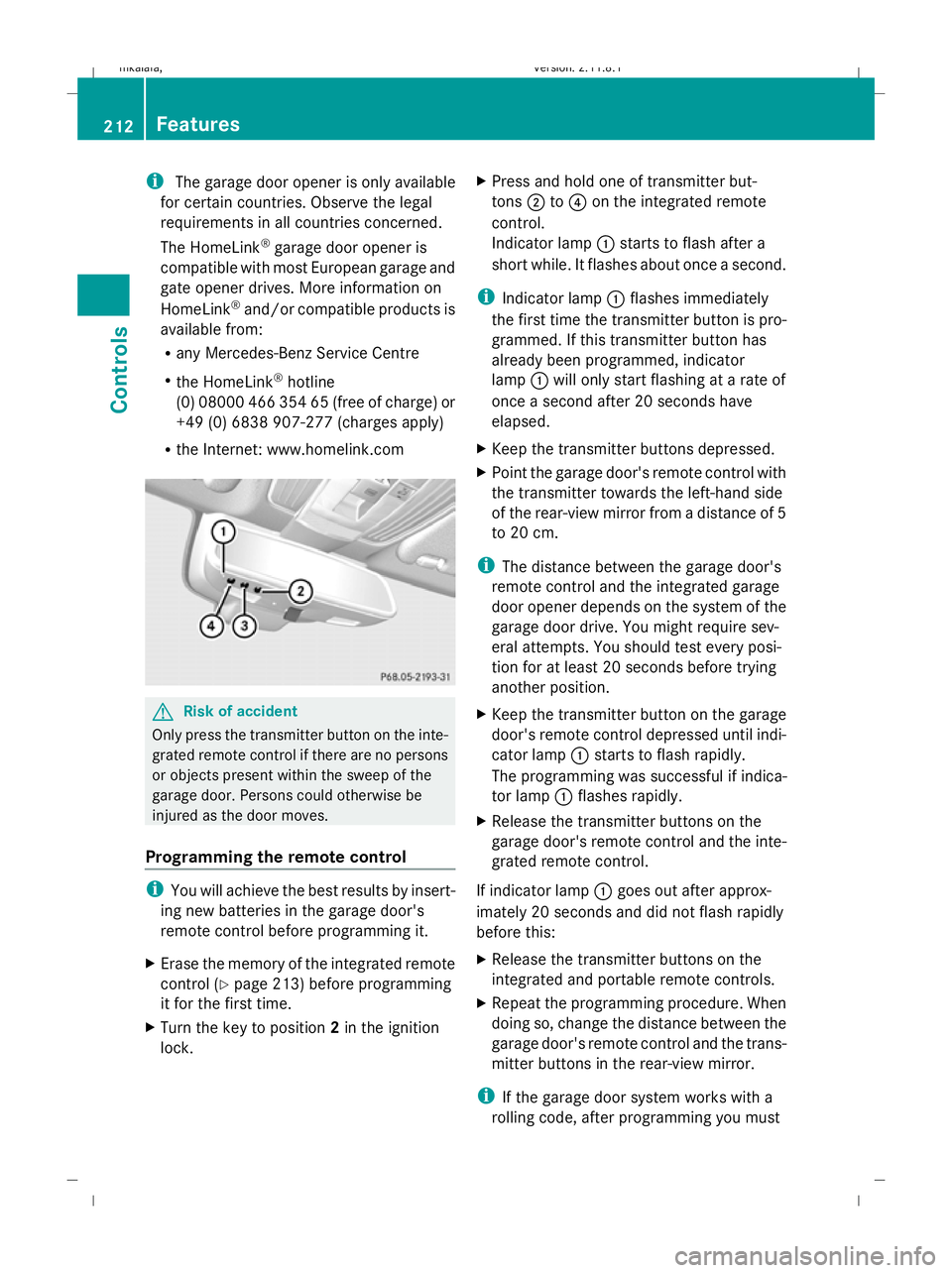
Press and hold one of transmitter but-
tons ;to? on the integrated remote
control.
Indicator lamp :starts to flash after a
short while. It flashes about once a second.
i Indicator lamp :flashes immediately
the first time the transmitter button is pro-
grammed. If this transmitter button has
already been programmed, indicator
lamp :will only start flashing at a rate of
once a second after 20 seconds have
elapsed.
X Keep the transmitter buttons depressed.
X Point the garage door's remote control with
the transmitter towards the left-hand side
of the rear-view mirror from a distance of 5
to 20 cm.
i The distance between the garage door's
remote control and the integrated garage
door opener depends on the system of the
garage door drive. You might require sev-
eral attempts. You should test every posi-
tion for at least 20 seconds before trying
another position.
X Keep the transmitter button on the garage
door's remote control depressed until indi-
cator lamp :starts to flash rapidly.
The programming was successful if indica-
tor lamp :flashes rapidly.
X Release the transmitter buttons on the
garage door's remote control and the inte-
grated remote control.
If indicator lamp :goes out after approx-
imately 20 seconds and did not flash rapidly
before this:
X Release the transmitter buttons on the
integrated and portable remote controls.
X Repeat the programming procedure. When
doing so, change the distance between the
garage door's remote control and the trans-
mitter buttons in the rear-view mirror.
i If the garage door system works with a
rolling code, after programming you must 212
FeaturesControls
212_AKB; 2; 4, en-GB
mkalafa,
Version: 2.11.8.1 2009-05-05T14:17:16+02:00 - Seite 212
Dateiname: 6515346702_buchblock.pdf; erzeugt am 07. May 2009 14:16:52; WK
Page 230 of 373

The tyre pressure loss warning system does
not replace the need to regularly check your
vehicle's tyre pressures, since an even loss of
pressure on several tyres at the same time
cannot be detected by the tyre pressure loss
warning system.
The tyre pressure monitor is not able to warn
you of a sudden loss of pressure, e.g. if the
tyre is penetrated by a foreign object.
In the event of a sudden loss of pressure, bring
the vehicle to a halt by braking carefully. Do
not make any sudden steering movements
when doing so.
The function of the tyre pressure loss warning
system is limited or delayed if:
R snow chains are fitted to your vehicle's
tyres.
R road conditions are wintry.
R you are driving on sand or gravel.
R you adopt a very sporty driving style (cor-
nering at high speeds or driving with high
rates of acceleration).
R you are towing a very heavy or large trailer.
R you are driving with a heavy load (in the
vehicle or on the roof).
Restarting the tyre pressure loss warn-
ing system Restart the tyre pressure loss warning system
if you have:
R
changed the tyre pressure
R changed the wheels or tyres
R fitted new wheels or tyres
X Before restarting, consult the table of tyre
pressures on the inside of the fuel filler flap
to ensure that the tyre pressure in all four
tyres is set correctly for the respective
operating conditions.
X Observe the notes in the section on tyre
pressures (Y page 225). G
Risk of accident
The tyre pressure loss warning system can
only give reliable warnings if you have set the
correct tyre pressure.
If an incorrect tyre pressure is set, these
incorrect values will be monitored.
A tyre with insufficient pressure results in
vehicle instability when driving, thus increas-
ing the risk of an accident.
X Make sure that the key is in position 2in
the ignition lock.
In the multi-function display you will see the
standard display (Y page 119).
X Press the =or; button to select the
Service menu.
X Press the 9or: button to select
Tyre pressure.
X Press the abutton.
The multi-function display shows the mes-
sage:
Run Flat Indicator active Restart
with OK
If you wish to confirm the restart:
X Press the abutton.
The multi-function display shows the mes-
sage:
Tyre press. now OK?
X Press the 9or: button to select
Yes.
X Press the abutton.
You will see the following message in the
multi-function display:
Run Flat Indicator restarted
After a teach-in period, the tyre pressure
loss warning system will monitor the set
tyre pressures of all four tyres.
If you wish to cancel the restart:
X Press the %button.
or
X When the Tyre press. now OK? message
appears, press 9or: to select
Cancel. Tyres and wheels
227Operation
212_AKB; 2; 4, en-GB
mkalafa, Version: 2.11.8.1 2009-05-05T14:17:16+02:00 - Seite 227 Z
Dateiname: 6515346702_buchblock.pdf; erzeugt am 07. May 2009 14:16:57; WK
Page 241 of 373
X
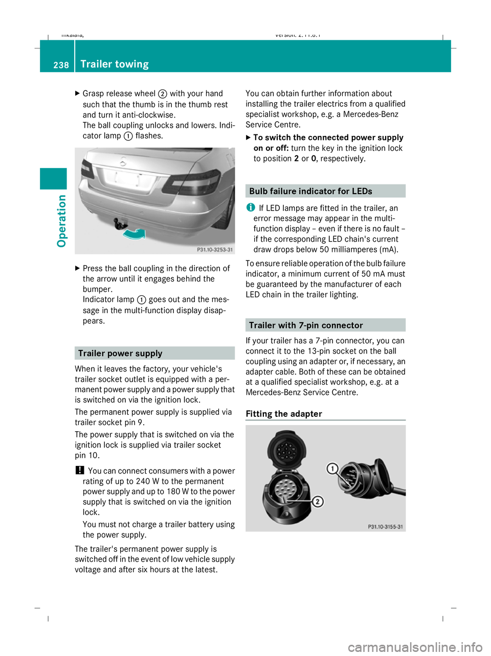
Grasp release wheel ;with your hand
such that the thumb is in the thumb rest
and turn it anti-clockwise.
The ball coupling unlocks and lowers. Indi-
cator lamp :flashes. X
Press the ball coupling in the direction of
the arrow until it engages behind the
bumper.
Indicator lamp :goes out and the mes-
sage in the multi-function display disap-
pears. Trailer power supply
When it leaves the factory, your vehicle's
trailer socket outlet is equipped with a per-
manent power supply and a power supply that
is switched on via the ignition lock.
The permanent power supply is supplied via
trailer socket pin 9.
The power supply that is switched on via the
ignition lock is supplied via trailer socket
pin 10.
! You can connect consumers with a power
rating of up to 240 W to the permanent
power supply and up to 180 W to the power
supply that is switched on via the ignition
lock.
You must not charge a trailer battery using
the power supply.
The trailer's permanent power supply is
switched off in the event of low vehicle supply
voltage and after six hours at the latest. You can obtain further information about
installing the trailer electrics from a qualified
specialist workshop, e.g. a Mercedes-Benz
Service Centre.
X
To switch the connected power supply
on or off: turn the key in the ignition lock
to position 2or 0, respectively. Bulb failure indicator for LEDs
i If LED lamps are fitted in the trailer, an
error message may appear in the multi-
function display – even if there is no fault –
if the corresponding LED chain's current
draw drops below 50 milliamperes (mA).
To ensure reliable operation of the bulb failure
indicator, a minimum current of 50 mA must
be guaranteed by the manufacturer of each
LED chain in the trailer lighting. Trailer with 7-pin connector
If your trailer has a 7-pin connector, you can
connect it to the 13-pin socket on the ball
coupling using an adapter or, if necessary, an
adapter cable. Both of these can be obtained
at a qualified specialist workshop, e.g. at a
Mercedes-Benz Service Centre.
Fitting the adapter 238
Trailer towingOperation
212_AKB; 2; 4, en-GB
mkalafa
,V ersion: 2.11.8.1
2009-05-05T14:17:16+02:00 - Seite 238
Dateiname: 6515346702_buchblock.pdf; erzeugt am 07. May 2009 14:17:01; WK
Page 242 of 373
X
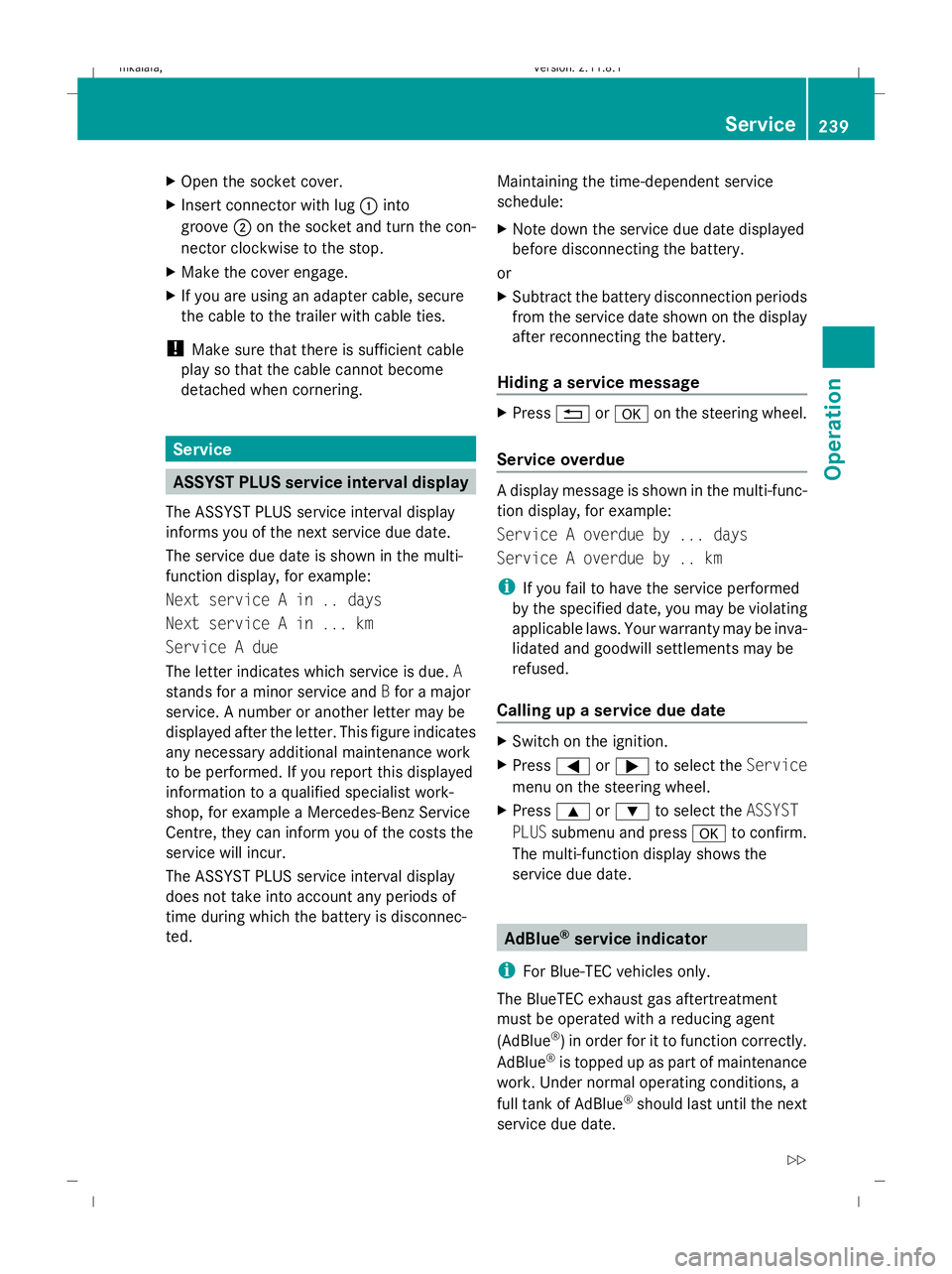
Open the socket cover.
X Insert connector with lug :into
groove ;on the socket and turn the con-
nector clockwise to the stop.
X Make the cover engage.
X If you are using an adapter cable, secure
the cable to the trailer with cable ties.
! Make sure that there is sufficient cable
play so that the cable cannot become
detached when cornering. Service
ASSYST PLUS service interval display
The ASSYST PLUS service interval display
informs you of the next service due date.
The service due date is shown in the multi-
function display, for example:
Next service A in .. days
Next service A in ... km
Service A due
The letter indicates which service is due. A
stands for a minor service and Bfor a major
service. A number or another letter may be
displayed after the letter. This figure indicates
any necessary additional maintenance work
to be performed. If you report this displayed
information to a qualified specialist work-
shop, for example a Mercedes-Benz Service
Centre, they can inform you of the costs the
service will incur.
The ASSYST PLUS service interval display
does not take into account any periods of
time during which the battery is disconnec-
ted. Maintaining the time-dependent service
schedule:
X
Note down the service due date displayed
before disconnecting the battery.
or
X Subtract the battery disconnection periods
from the service date shown on the display
after reconnecting the battery.
Hiding a service message X
Press %ora on the steering wheel.
Service overdue A display message is shown in the multi-func-
tion display, for example:
Service A overdue by ... days
Service A overdue by .. km
i
If you fail to have the service performed
by the specified date, you may be violating
applicable laws. Your warranty may be inva-
lidated and goodwill settlements may be
refused.
Calling up a service due date X
Switch on the ignition.
X Press =or; to select the Service
menu on the steering wheel.
X Press 9or: to select the ASSYST
PLUS submenu and press ato confirm.
The multi-function display shows the
service due date. AdBlue
®
service indicator
i For Blue-TEC vehicles only.
The BlueTEC exhaust gas aftertreatment
must be operated with a reducing agent
(AdBlue ®
) in order for it to function correctly.
AdBlue ®
is topped up as part of maintenance
work. Under normal operating conditions, a
full tank of AdBlue ®
should last until the next
service due date. Service
239Operation
212_AKB; 2; 4, en-GB
mkalafa, Version: 2.11.8.1 2009-05-05T14:17:16+02:00 - Seite 239 Z
Dateiname: 6515346702_buchblock.pdf; erzeugt am 07. May 2009 14:17:01; WK
Page 245 of 373

products, or gloss preservers such as wax.
These products are only suitable for high-
gloss finishes. Using them on a vehicle with
a matt finish results in serious damage to
the surface (gleaming, spotted areas).
Always have paintwork repairs carried out
at a qualified specialist workshop, e.g. a
Mercedes-Benz Service Centre.
i From the range of available Mercedes-
Benz care products, use only the insect
remover and the car shampoo.
Cleaning the paintwork Scratches, corrosive deposits, areas affected
by corrosion and damage caused by inade-
quate care cannot always be completely
repaired. In such cases, visit a qualified spe-
cialist workshop immediately, e.g. a
Mercedes-Benz Service Centre.
X Remove the following types of dirt immedi-
ately, whilst avoiding rubbing too hard.
Soak:
R insect remains with insect remover
R bird droppings with water
and rinse off the treated surface after-
wards.
Remove:
R tree resin, oils, fuels and greases by rub-
bing gently with a cloth soaked in petro-
leum ether or lighter fluid.
R tar stain with tar remover
R wax with silicone remover
! Do not affix:
R stickers
R films
R magnetic plates or similar items
to painted surfaces. Otherwise, you could
damage the paintwork. Cleaning the wheels !
Do not use acidic wheel cleaners to
remove brake dust. This could damage
wheel bolts and brake components.
Cleaning the windows X
Clean the inside and outside of the win-
dows with a damp cloth and a cleaning
product approved and recommended by
Mercedes-Benz.
! Clean the water drainage channels of the
windscreen and the rear window at regular
intervals. Under certain circumstances,
deposits such as leaves, petals and pollen
may prevent water from draining away
leading to corrosion damage.
Cleaning the wiper blades G
Risk of injury
Before cleaning the windscreen or wiper
blades, turn the key to position 0in the igni-
tion lock or press the Start/Stop button* until
all indicator lamps have gone out in the instru-
ment cluster. The windscreen wipers could
otherwise move and cause injury.
! Do not clean the wiper blades too often
and do not rub them too hard, as this will
result in damage to the graphite coating.
This could cause wiper noise.
X Fold the wiper arms away from the wind-
screen.
X Clean the wiper blades carefully with a
damp cloth.
X Fold the wiper arms back again before
switching on the ignition.
Cleaning the headlamps X
Clean the plastic lenses of the headlamps
with a wet sponge and windscreen washer
fluid or cleaning cloths. 242
CareOperation
* optional
212_AKB; 2; 4, en-GB
mkalafa,
Version: 2.11.8.1 2009-05-05T14:17:16+02:00 - Seite 242
Dateiname: 6515346702_buchblock.pdf; erzeugt am 07. May 2009 14:17:01; WK
Page 255 of 373
outside temperature, warning and indicator
lamps, display messages or the failure of sys-
tems. The vehicle’s handling characteristics
may be affected. Adapt your driving style and
speed accordingly.
Immediately consult a qualified specialist
workshop which has the necessary specialist
knowledge and tools to carry out the work
required. Mercedes-Benz recommends that
you use a Mercedes-Benz Service Centre for
this purpose. In particular, work relevant to
safety or on safety-related systems must be
carried out at a qualified specialist workshop.
When you stop and park the vehicle, please
observe the instructions provided for HOLD
(Y page 151)and parking (Y page 107).
Calling up display messages The on-board computer saves certain display
messages, which you can call up.
X Press =or; on the steering wheel
to select the Servicemenu.
If there are display messages, the multi-
function display shows, e.g. 2 messages.
X Using 9or: select the entry, e.g.
2 messages. X
Confirm with a.
X Using :or9 scroll through the dis-
play messages.
Hiding display messages You cannot hide display messages of the
highest priority. The multi-function display
shows these messages continuously until
their causes have been remedied.
Use the buttons on the multi-function steer-
ing wheel.
X
Use the aor% button on the steer-
ing wheel to hide the display message.
The following tables contain all the display
messages. Text messages
G
Risk of accident and injury
The operating safety of the vehicle can be compromised if maintenance work is carried out
incorrectly. This could cause you to lose control of the vehicle and cause an accident. The safety
systems may also not be able to protect you or others as they are designed to do.
Always have maintenance work carried out at a qualified specialist workshop. The qualified spe-
cialist workshop must have the necessary specialist knowledge and tools to carry out the work
required. Mercedes-Benz recommends that you use a Mercedes-Benz Service Centre for this
purpose. In particular, work relevant to safety or on safety-related systems must be carried out
at a qualified specialist workshop. 252
Display messagesPractical advice
212_AKB; 2; 4, en-GB
mkalafa,
Version: 2.11.8.1 2009-05-05T14:17:16+02:00 - Seite 252
Dateiname: 6515346702_buchblock.pdf; erzeugt am 07. May 2009 14:17:07; WK
Page 266 of 373
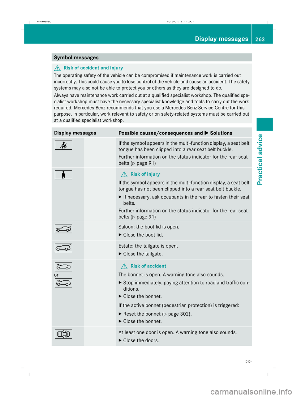
Symbol messages
G
Risk of accident and injury
The operating safety of the vehicle can be compromised if maintenance work is carried out
incorrectly. This could cause you to lose control of the vehicle and cause an accident. The safety
systems may also not be able to protect you or others as they are designed to do.
Always have maintenance work carried out at a qualified specialist workshop. The qualified spe-
cialist workshop must have the necessary specialist knowledge and tools to carry out the work
required. Mercedes-Benz recommends that you use a Mercedes-Benz Service Centre for this
purpose. In particular, work relevant to safety or on safety-related systems must be carried out
at a qualified specialist workshop. Display messages
Possible causes/consequences and
X
X Solutions 7 If the symbol appears in the multi-function display, a seat belt
tongue has been clipped into a rear seat belt buckle.
Further information on the status indicator for the rear seat
belts (Y
page 91) a G
Risk of injury
If the symbol appears in the multi-function display, a seat belt
tongue has not been clipped into a rear seat belt buckle.
X If necessary, ask occupants in the rear to fasten their seat
belts.
Further information on the status indicator for the rear seat
belts (Y page 91) N Saloon: the boot lid is open.
X
Close the boot lid. A Estate: the tailgate is open.
X
Close the tailgate. M
or
? G
Risk of accident
The bonnet is open. A warning tone also sounds.
X Stop immediately, paying attention to road and traffic con-
ditions.
X Close the bonnet.
If the active bonnet (pedestrian protection) is triggered:
X Reset the bonnet (Y page 302).
X Close the bonnet. ; At least one door is open. A warning tone also sounds.
X
Close the doors. Display messages
263Practical advice
212_AKB; 2; 4, en-GB
mkalafa, Version: 2.11.8.1 2009-05-05T14:17:16+02:00 - Seite 263 Z
Dateiname: 6515346702_buchblock.pdf; erzeugt am 07. May 2009 14:17:09; WK
Page 307 of 373
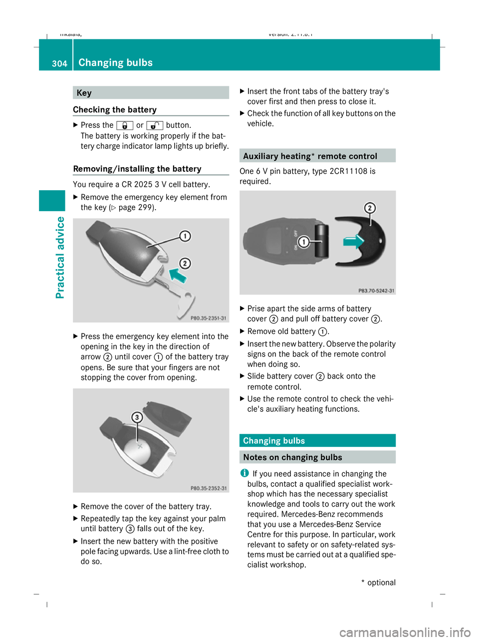
Key
Checking the battery X
Press the &or% button.
The battery is working properly if the bat-
tery charge indicator lamp lights up briefly.
Removing/installing the battery You require a CR 2025 3 V cell battery.
X Remove the emergency key element from
the key (Y page 299). X
Press the emergency key element into the
opening in the key in the direction of
arrow ;until cover :of the battery tray
opens. Be sure that your fingers are not
stopping the cover from opening. X
Remove the cover of the battery tray.
X Repeatedly tap the key against your palm
until battery =falls out of the key.
X Insert the new battery with the positive
pole facing upwards. Use a lint-free cloth to
do so. X
Insert the front tabs of the battery tray's
cover first and then press to close it.
X Check the function of all key buttons on the
vehicle. Auxiliary heating* remote control
One 6 V pin battery, type 2CR11108 is
required. X
Prise apart the side arms of battery
cover ;and pull off battery cover ;.
X Remove old battery :.
X Insert the new battery. Observe the polarity
signs on the back of the remote control
when doing so.
X Slide battery cover ;back onto the
remote control.
X Use the remote control to check the vehi-
cle's auxiliary heating functions. Changing bulbs
Notes on changing bulbs
i If you need assistance in changing the
bulbs, contact a qualified specialist work-
shop which has the necessary specialist
knowledge and tools to carry out the work
required. Mercedes-Benz recommends
that you use a Mercedes-Benz Service
Centre for this purpose. In particular, work
relevant to safety or on safety-related sys-
tems must be carried out at a qualified spe-
cialist workshop. 304
Changing bulbsPractical advice
* optional
212_AKB; 2; 4, en-GB
mkalafa,
Version: 2.11.8.1 2009-05-05T14:17:16+02:00 - Seite 304
Dateiname: 6515346702_buchblock.pdf; erzeugt am 07. May 2009 14:17:18; WK