2009 MERCEDES-BENZ E-CLASS SALOON remote control
[x] Cancel search: remote controlPage 214 of 373
When you take the key out of the ignition lock,
the mobile phone stays on but you can no
longer use the hands-free system.
If you are making a call and you would like to
take the key out of the ignition lock, first
remove the mobile phone from the bracket.
Otherwise, the call will be ended.
Sliding adapter for the mobile phone
bracket (automatic vehicles with
DIRECT SELECT selector lever*) Certain mobile phone brackets require a slid-
ing adapter so the bracket can be installed
correctly.
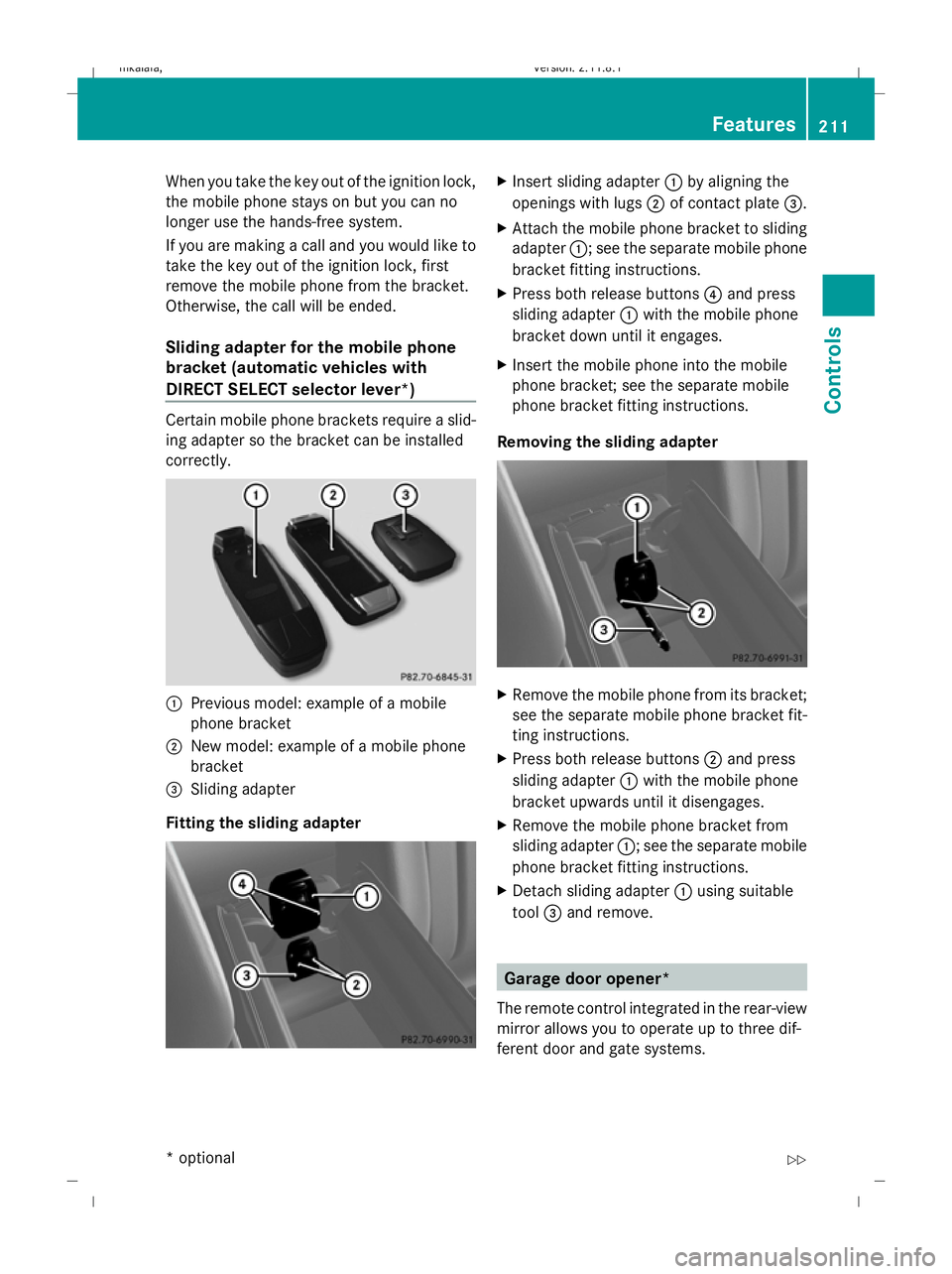
:
Previous model: example of a mobile
phone bracket
; New model: example of a mobile phone
bracket
= Sliding adapter
Fitting the sliding adapter X
Insert sliding adapter :by aligning the
openings with lugs ;of contact plate =.
X Attach the mobile phone bracket to sliding
adapter :; see the separate mobile phone
bracket fitting instructions.
X Press both release buttons 4and press
sliding adapter :with the mobile phone
bracket down until it engages.
X Insert the mobile phone into the mobile
phone bracket; see the separate mobile
phone bracket fitting instructions.
Removing the sliding adapter X
Remove the mobile phone from its bracket;
see the separate mobile phone bracket fit-
ting instructions.
X Press both release buttons ;and press
sliding adapter :with the mobile phone
bracket upwards until it disengages.
X Remove the mobile phone bracket from
sliding adapter :; see the separate mobile
phone bracket fitting instructions.
X Detach sliding adapter :using suitable
tool =and remove. Garage door opener*
The remote control integrated in the rear-view
mirror allows you to operate up to three dif-
ferent door and gate systems. Features
211Controls
* optional
212_AKB; 2; 4, en-GB
mkalafa,
Version: 2.11.8.1 2009-05-05T14:17:16+02:00 - Seite 211 Z
Dateiname: 6515346702_buchblock.pdf; erzeugt am 07. May 2009 14:16:52; WK
Page 215 of 373
i
The garage door opener is only available
for certain countries. Observe the legal
requirements in all countries concerned.
The HomeLink ®
garage door opener is
compatible with most European garage and
gate opener drives. More information on
HomeLink ®
and/or compatible products is
available from:
R any Mercedes-Benz Service Centre
R the HomeLink ®
hotline
(0) 08000 466 354 65 (free of charge) or
+49 (0) 6838 907-277 (charges apply)
R the Internet: www.homelink.com G
Risk of accident
Only press the transmitter button on the inte-
grated remote control if there are no persons
or objects present within the sweep of the
garage door. Persons could otherwise be
injured as the door moves.
Programming the remote control i
You will achieve the best results by insert-
ing new batteries in the garage door's
remote control before programming it.
X Erase the memory of the integrated remote
control (Y page 213) before programming
it for the first time.
X Turn the key to position 2in the ignition
lock. X
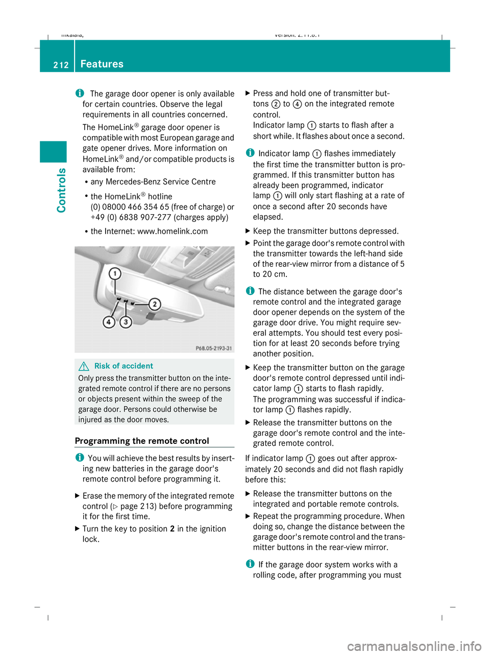
Press and hold one of transmitter but-
tons ;to? on the integrated remote
control.
Indicator lamp :starts to flash after a
short while. It flashes about once a second.
i Indicator lamp :flashes immediately
the first time the transmitter button is pro-
grammed. If this transmitter button has
already been programmed, indicator
lamp :will only start flashing at a rate of
once a second after 20 seconds have
elapsed.
X Keep the transmitter buttons depressed.
X Point the garage door's remote control with
the transmitter towards the left-hand side
of the rear-view mirror from a distance of 5
to 20 cm.
i The distance between the garage door's
remote control and the integrated garage
door opener depends on the system of the
garage door drive. You might require sev-
eral attempts. You should test every posi-
tion for at least 20 seconds before trying
another position.
X Keep the transmitter button on the garage
door's remote control depressed until indi-
cator lamp :starts to flash rapidly.
The programming was successful if indica-
tor lamp :flashes rapidly.
X Release the transmitter buttons on the
garage door's remote control and the inte-
grated remote control.
If indicator lamp :goes out after approx-
imately 20 seconds and did not flash rapidly
before this:
X Release the transmitter buttons on the
integrated and portable remote controls.
X Repeat the programming procedure. When
doing so, change the distance between the
garage door's remote control and the trans-
mitter buttons in the rear-view mirror.
i If the garage door system works with a
rolling code, after programming you must 212
FeaturesControls
212_AKB; 2; 4, en-GB
mkalafa,
Version: 2.11.8.1 2009-05-05T14:17:16+02:00 - Seite 212
Dateiname: 6515346702_buchblock.pdf; erzeugt am 07. May 2009 14:16:52; WK
Page 216 of 373
synchronise the remote control integrated
in the rear-view mirror with the garage door
system receiver.
You will find further information in the
garage door opening system's operating
instructions, e.g. the sections on "Synchro-
nising the transmitter" or "Registering a
new transmitter". You can also call the hot-
line mentioned above.
Opening or closing the garage door Once programmed, the integrated remote
control will assume the function of the garage
door system's remote control. Please read
the operating instructions for the garage door
system.
X Turn the key to position 2in the ignition
lock.
X Press the transmitter button on the rear-
view mirror that you have programmed to
operate the garage door.
Garage door system with fixed code: indi-
cator lamp :lights up continuously.
Garage door system with rolling code: indi-
cator lamp :flashes briefly and then lights
up for approximately two seconds. This is
repeated for up to 20 seconds.
i The transmitter will transmit a signal for
as long as the transmitter button is being
pressed. The transmission will be halted
after a maximum of 20 seconds and indi-
cator lamp :will flash. Press the trans-
mitter button again, if necessary.
Clearing the remote control memory X
Turn the key to position 2in the ignition
lock.
X Press and hold transmitter buttons ;
and ?for approximately 20 seconds until
indicator lamp :flashes rapidly.
The memory is cleared.
i You should clear the remote control mem-
ory before selling the vehicle. Floormat* on the driver's side
G
Risk of accident
Make sure that there is sufficient clearance
around the pedals when floormats are used,
and that the floormats are properly secured.
The floormats must be correctly secured at all
times using retainers and press-studs.
Before you drive off, check the floormats and
secure if necessary. A floormat which is not
properly secured can slip and, thereby, inter-
fere with the movement of the pedals.
Do not place floormats on top of one another. X
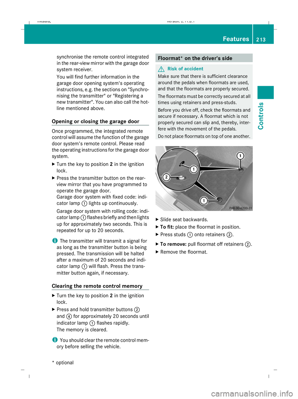
Slide seat backwards.
X To fit: place the floormat in position.
X Press studs :onto retainers ;.
X To remove: pull floormat off retainers ;.
X Remove the floormat. Features
213Controls
* optional
212_AKB; 2; 4, en-GB
mkalafa,
Version: 2.11.8.1 2009-05-05T14:17:16+02:00 - Seite 213 Z
Dateiname: 6515346702_buchblock.pdf; erzeugt am 07. May 2009 14:16:52; WK
Page 250 of 373
Where will I find...?
...........................248
Display messages ............................. 251
Troubleshooting ................................ 278
Locking/unlocking in an emer-
gency ................................................. 299
Resetting the active bonnet
(pedestrian protection) after trig-
gering ................................................. 302
Resetting triggered NECK-PRO
head restraints .................................. 303
Replacing batteries (key and
remote control) ................................. 303
Changing bulbs ................................. 304
Replacing the wiper blades ..............308
Flat tyre ............................................. 309
Battery ............................................... 319
Jump-starting .................................... 323
Towing and tow-starting ..................324
Fuses .................................................. 327 247Practical advice
212_AKB; 2; 4, en-GB
mkalafa,
Version: 2.11.8.1 2009-05-05T14:17:16+02:00 - Seite 247
Dateiname: 6515346702_buchblock.pdf; erzeugt am 07. May 2009 14:17:04; WK
Page 299 of 373

Exterior mirrors
Problem
Possible causes/consequences and
X
X Solutions An exterior mirror has
been pushed out of
position.
Vehicles with exterior mirrors that cannot be folded in/out elec-
trically:
X
Move the exterior mirror into the correct position manually.
Vehicles with electrically folding exterior mirrors*:
X Press the mirror-folding button* (Y page 86) repeatedly until
you hear a distinct click.
The mirror housing is engaged again and you can adjust the
mirror as usual ( Ypage 86). Key
Problem
Possible causes/consequences and
X
X Solutions You cannot lock or
unlock the vehicle
using the key. The key batteries are discharged or nearly discharged.
X
Point the tip of the key at the driver's door handle from close
range and try to unlock or lock the vehicle again.
If this does not work:
X Lock or unlock the vehicle using the emergency key element
(Y page 299). The key is faulty.
X
Lock/unlock the vehicle as described in the "Opening and clos-
ing in an emergency" section (Y page 299).
X Have the key checked at a qualified specialist workshop. You can no longer lock
or unlock the vehicle
using KEYLESS GO*.
KEYLESS GO* is in standby mode because the vehicle has not
been unlocked for an extended period.
X
Pull the door handle and then turn the key to position 2in the
ignition lock. KEYLESS-GO* is malfunctioning.
X
Lock/unlock the vehicle using the remote control function of
the key. Point the tip of the key at the driver's door handle from
close range and press the %/&button.
X Have the key checked at a qualified specialist workshop. There is interference from a powerful source of radio waves.
X
Lock/unlock the vehicle as described in the "Opening and clos-
ing in an emergency" section (Y page 299).296
TroubleshootingPractical advice
* optional
212_AKB; 2; 4, en-GB
mkalafa,
Version: 2.11.8.1 2009-05-05T14:17:16+02:00 - Seite 296
Dateiname: 6515346702_buchblock.pdf; erzeugt am 07. May 2009 14:17:14; WK
Page 301 of 373
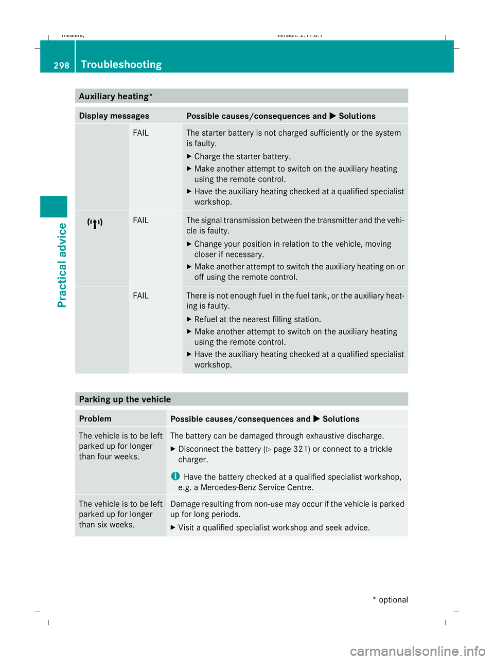
Auxiliary heating*
Display messages
Possible causes/consequences and
X
X Solutions FAIL The starter battery is not charged sufficiently or the system
is faulty.
X
Charge the starter battery.
X Make another attempt to switch on the auxiliary heating
using the remote control.
X Have the auxiliary heating checked at a qualified specialist
workshop. $ FAIL The signal transmission between the transmitter and the vehi-
cle is faulty.
X
Change your position in relation to the vehicle, moving
closer if necessary.
X Make another attempt to switch the auxiliary heating on or
off using the remote control. © FAIL There is not enough fuel in the fuel tank, or the auxiliary heat-
ing is faulty.
X
Refuel at the nearest filling station.
X Make another attempt to switch on the auxiliary heating
using the remote control.
X Have the auxiliary heating checked at a qualified specialist
workshop. Parking up the vehicle
Problem
Possible causes/consequences and
X XSolutions The vehicle is to be left
parked up for longer
than four weeks. The battery can be damaged through exhaustive discharge.
X
Disconnect the battery (Y page 321) or connect to a trickle
charger.
i Have the battery checked at a qualified specialist workshop,
e.g. a Mercedes-Benz Service Centre. The vehicle is to be left
parked up for longer
than six weeks. Damage resulting from non-use may occur if the vehicle is parked
up for long periods.
X
Visit a qualified specialist workshop and seek advice. 298
TroubleshootingPractical advice
* optional
212_AKB; 2; 4, en-GB
mkalafa,
Version: 2.11.8.1 2009-05-05T14:17:16+02:00 - Seite 298
Dateiname: 6515346702_buchblock.pdf; erzeugt am 07. May 2009 14:17:14; WK
Page 306 of 373
bonnet
:upwards until the relevant bon-
net actuator cover ;no longer moves.
Bonnet actuator covers ;should now lie
flat against housing =(arrow).
X Close bonnet :(Ypage 219).
If bonnet :cannot be closed or the L
symbol appears in the multi-function display,
repeat the steps again. G
Risk of accident
If the bonnet can still not be engaged properly
or the Lsymbol appears in the multi-func-
tion display, do not continue driving. Other-
wise, the bonnet may open when driving and
block your view. Consult a qualified specialist
workshop. Otherwise, you may cause an acci-
dent and injure yourself and others. Resetting triggered NECK-PRO head
restraints
If the NECK-PRO head restraints are triggered
in an accident, you must reset the head
restraints on the driver's and the front-pas-
senger's seats. Otherwise, the additional pro-
tection will not be available in the event of
another rear-end collision. You can recognise
when head restraints have been triggered by
the fact that they have moved forwards and
can no longer be adjusted.
Mercedes-Benz recommends that you have
NECK-PRO head restraints checked at a quali-
fied specialist workshop, e.g. a Mercedes-
Benz Service Centre, following a rear-end col-
lision.
i This work requires a lot of strength. If you
have difficulty resetting the head
restraints, have this work carried out at a
qualified specialist workshop, e.g. a
Mercedes-Benz Service Centre. Example: Saloon
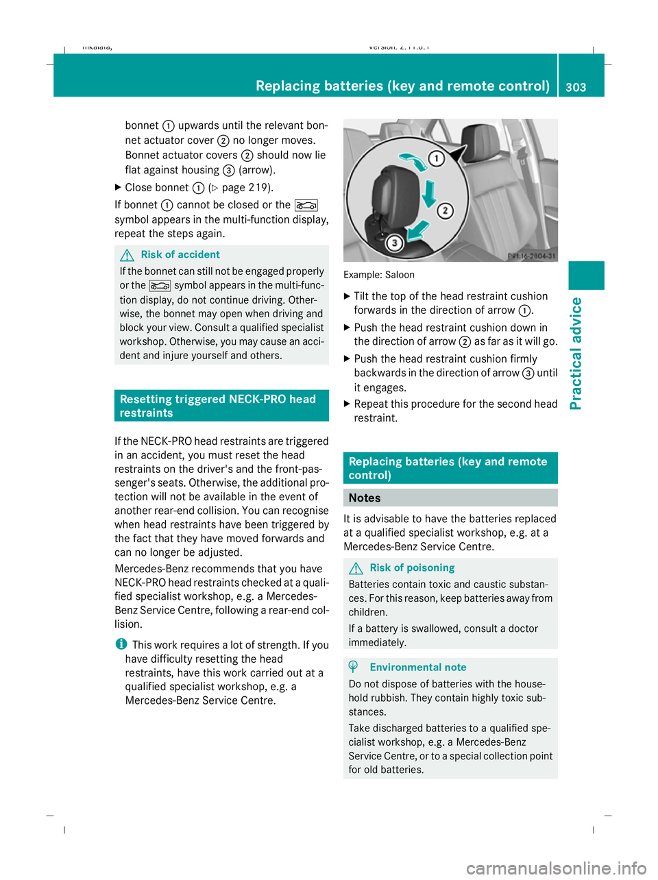
X
Tilt the top of the head restraint cushion
forwards in the direction of arrow :.
X Push the head restraint cushion down in
the direction of arrow ;as far as it will go.
X Push the head restraint cushion firmly
backwards in the direction of arrow =until
it engages.
X Repeat this procedure for the second head
restraint. Replacing batteries (key and remote
control)
Notes
It is advisable to have the batteries replaced
at a qualified specialist workshop, e.g. at a
Mercedes-Benz Service Centre. G
Risk of poisoning
Batteries contain toxic and caustic substan-
ces. For this reason, keep batteries away from
children.
If a battery is swallowed, consult a doctor
immediately. H
Environmental note
Do not dispose of batteries with the house-
hold rubbish. They contain highly toxic sub-
stances.
Take discharged batteries to a qualified spe-
cialist workshop, e.g. a Mercedes-Benz
Service Centre, or to a special collection point
for old batteries. Replacing batteries (key and remote control)
303Practical advice
212_AKB; 2; 4, en-GB
mkalafa,Version: 2.11.8.1 2009-05-05T14:17:16+02:00 - Seite 303 Z
Dateiname: 6515346702_buchblock.pdf; erzeugt am 07. May 2009 14:17:17; WK
Page 307 of 373
Key
Checking the battery X
Press the &or% button.
The battery is working properly if the bat-
tery charge indicator lamp lights up briefly.
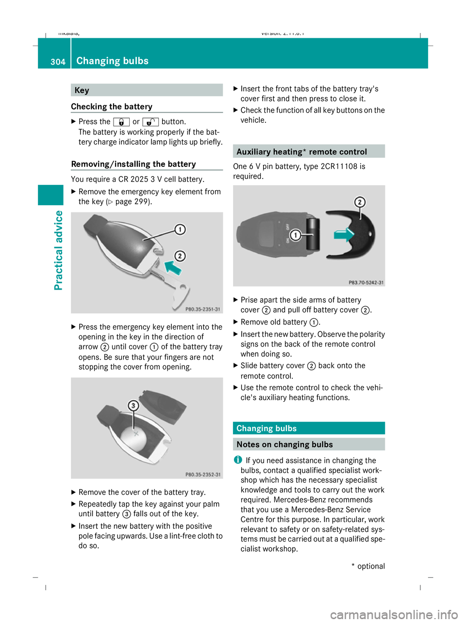
Removing/installing the battery You require a CR 2025 3 V cell battery.
X Remove the emergency key element from
the key (Y page 299). X
Press the emergency key element into the
opening in the key in the direction of
arrow ;until cover :of the battery tray
opens. Be sure that your fingers are not
stopping the cover from opening. X
Remove the cover of the battery tray.
X Repeatedly tap the key against your palm
until battery =falls out of the key.
X Insert the new battery with the positive
pole facing upwards. Use a lint-free cloth to
do so. X
Insert the front tabs of the battery tray's
cover first and then press to close it.
X Check the function of all key buttons on the
vehicle. Auxiliary heating* remote control
One 6 V pin battery, type 2CR11108 is
required. X
Prise apart the side arms of battery
cover ;and pull off battery cover ;.
X Remove old battery :.
X Insert the new battery. Observe the polarity
signs on the back of the remote control
when doing so.
X Slide battery cover ;back onto the
remote control.
X Use the remote control to check the vehi-
cle's auxiliary heating functions. Changing bulbs
Notes on changing bulbs
i If you need assistance in changing the
bulbs, contact a qualified specialist work-
shop which has the necessary specialist
knowledge and tools to carry out the work
required. Mercedes-Benz recommends
that you use a Mercedes-Benz Service
Centre for this purpose. In particular, work
relevant to safety or on safety-related sys-
tems must be carried out at a qualified spe-
cialist workshop. 304
Changing bulbsPractical advice
* optional
212_AKB; 2; 4, en-GB
mkalafa,
Version: 2.11.8.1 2009-05-05T14:17:16+02:00 - Seite 304
Dateiname: 6515346702_buchblock.pdf; erzeugt am 07. May 2009 14:17:18; WK