2009 MERCEDES-BENZ E-CLASS SALOON clock
[x] Cancel search: clockPage 220 of 373

require draining of the fuel tank and fuel
lines. Notify a qualified specialist workshop
and have the fuel tank and fuel lines
drained completely.
When you open or close the vehicle with the
key or KEYLESS GO*, the fuel filler flap is
automatically unlocked or locked.
The position of the fuel filler cap is to the rear
on the right. The position of the fuel filler cap
is displayed in the instrument cluster 8.
The arrow next to the filling pump indicates
the side of the vehicle. Saloon (example)
:
To open the fuel filler flap
; To insert the fuel filler cap
= Tyre pressure table
? Fuel type
X To open: press the fuel filler flap in the
direction of arrow :.
The fuel filler flap opens slightly.
X Open the fuel filler flap.
X Turn the fuel filler cap anti-clockwise and
remove it.
X Insert the fuel filler cap into the holder
bracket on the inside of filler flap ;.
X Only fill the tank until the pump nozzle
switches off.
! Overfilling the fuel tank could damage the
fuel system. X
To close: replace the fuel filler cap and turn
it clockwise. The fuel filler cap audibly
engages.
X Press the fuel filler flap closed until it
engages audibly. Petrol (EN 228)
! Refuel using only unleaded, sulphur-free
premium grade petrol with a minimum
octane number of 95 RON/85 MON con-
forming to European standard EN 228.
Otherwise, you could impair engine output
or damage the engine.
i As a temporary measure, only when the
recommended fuel is not available, you
may also use regular unleaded petrol,
91 RON/82.5 MON. This may reduce
engine performance and increase fuel con-
sumption. Avoid driving at full throttle.
In some countries, the fuel grade available
may not be adequate and could cause cok-
ing around the inlet valve. In such cases,
and in consultation with a Mercedes-Benz
Service Centre, the petrol may be mixed
with the additive recommended by
Mercedes-Benz (part no.
A000989254510). You must observe the
notes and mixing ratios specified on the
container.
Further information on "Fuel" (Y page 334).
E 350 CGI BlueEFFICIENCY !
Refuel using only unleaded, sulphur-free
premium grade petrol with a minimum
octane number of 95 RON/85 MON con-
forming to European standard EN 228.
Otherwise, you could impair engine output
or damage the engine.
i In some countries, the available petrol
may not be sufficiently low in sulphur. This
fuel can temporarily produce unpleasant
odours, especially on short journeys. As Refuelling
217Operation
* optional
212_AKB; 2; 4, en-GB
mkalafa,
Version: 2.11.8.1 2009-05-05T14:17:16+02:00 - Seite 217 Z
Dateiname: 6515346702_buchblock.pdf; erzeugt am 07. May 2009 14:16:54; WK
Page 224 of 373

E 300 (example)
X
Pull oil dipstick :out of the oil dipstick
tube.
X Wipe off oil dipstick :.
X Insert oil dipstick :into the oil dipstick
tube to the stop, and take it out again.
The oil level is correct if the level is between
the minimum mark =and maximum
mark ;.
X Top up the oil if necessary.
Topping up the engine oil H
Environmental note
When topping up the oil, take care not to spill
any. Oil must not be allowed to escape into
the soil or waterways. You would otherwise be
damaging the environment. Cap (example)
X
Turn cap :anti-clockwise and remove.
X Top up with the amount of oil required
(Y page 336). i
The difference in quantity between the
minimum mark and maximum mark is
approximately 2 litres.
i On vehicles with a 4-cylinder petrol
engine and vehicles with an 8-cylinder pet-
rol engine, the difference between the MIN
mark and the MAX mark is approximately
1.5 litres.
! Do not add too much oil. If too much oil
is added and the oil level is above the max-
imum mark on the dipstick, the engine or
catalytic converter could be damaged.
Have excess oil siphoned off.
X Replace cap :on the filler neck and
tighten clockwise.
Ensure that the cap locks into place
securely.
For further information on engine oil, see
(Y page 336). Coolant
Only check the coolant level when the vehicle
is on a level surface and the engine has cooled
down.
X Turn the key to position 2(Y page 75) in
the ignition lock.
X Check the coolant temperature gauge in
the instrument cluster. G
Risk of injury
The cooling system is pressurised. Therefore,
only unscrew the cap once the engine has
cooled down. The coolant temperature gauge
must display less than 70 †. Otherwise, you
could be scalded if hot coolant escapes. Engine compartment
221Operation
212_AKB; 2; 4, en-GB
mkalafa, Version: 2.11.8.1 2009-05-05T14:17:16+02:00 - Seite 221 Z
Dateiname: 6515346702_buchblock.pdf; erzeugt am 07. May 2009 14:16:56; WK
Page 225 of 373

The coolant expansion tank is located in the
engine compartment on the right when
viewed in the direction of travel. X
Slowly turn cap :half a turn anti-clock-
wise and allow excess pressure to escape.
X Turn cap :further anti-clockwise and
remove it.
There is sufficient coolant in expansion
tank ;if the coolant is level with marker
bar =in the filler neck when cold or
approximately 1.5 cm higher when hot.
X If necessary, top up with coolant which has
been tested and approved by Mercedes-
Benz.
X Replace cap :and tighten all the way to
the stop.
For further information on coolant, see
(Y page 338). Windscreen washer system/head-
lamp cleaning system*
The washer fluid reservoir for the windscreen
washer system and headlamp cleaning sys-
tem* is located in the engine compartment on the left-hand side when viewed in the
direction of travel. i
Add windscreen washer concentrate to
the washer fluid all year round. G
Risk of fire
Washer fluid concentrate is highly flammable.
Fire, naked flames and smoking are prohibi-
ted when washer fluid concentrate is being
handled.
! Only use washer fluid concentrate which
is suitable for plastic lenses. Unsuitable
washer fluid concentrate could damage the
plastic lenses of the headlamps.
X Mix the windscreen washer fluid in a con-
tainer beforehand.
X At temperatures above freezing:
Fill the washer fluid reservoir with a mix of
water and windscreen washer concentrate
(e.g. MB SummerFit).
X At temperatures below freezing:
Fill the washer fluid reservoir with a mix of
water, antifreeze additive and windscreen
washer concentrate (e.g. MB WinterFit).
Adapt the mixing ratio to the outside tem-
peratures.
X To open: pull cap:upwards by the tab.
X Top up with the premixed washer fluid.
X To close: press cap :onto the filler neck
until it engages. 222
Engine compartmentOperation
* optional
212_AKB; 2; 4, en-GB
mkalafa,
Version: 2.11.8.1 2009-05-05T14:17:16+02:00 - Seite 222
Dateiname: 6515346702_buchblock.pdf; erzeugt am 07. May 2009 14:16:56; WK
Page 237 of 373

Converting dipped-beam headlamps on
vehicles with halogen headlamps :
Protective cap
; Switchover lever
X Turn protective cap :anti-clockwise and
remove it.
X Push switchover lever ;down.
X Insert protective cap :and turn it clock-
wise.
When you are driving back on the same side
of the road as the country where the vehicle
is registered, have the headlamps changed
back to asymmetrical dipped beam as soon
as possible after crossing the border. Trailer towing
Folding out the ball coupling
Before you can tow a trailer with your vehicle,
you must fold out the ball coupling.
The release wheel is located behind the left-
hand side trim panel in the boot/luggage
compartment. G
Risk of accident
Make sure that the ball coupling is engaged,
either in its folded-out or folded-in position,
and that the indicator lamp is off.
Do not turn the release wheel when a trailer
is coupled up. Otherwise, the trailer might
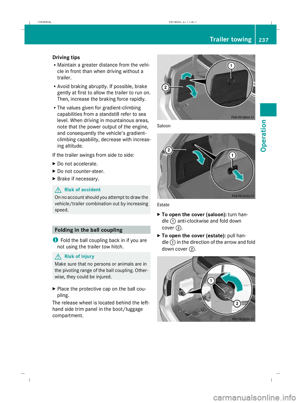
detach. Saloon
Estate
X
To open the cover (saloon): turn han-
dle :anti-clockwise and fold down
cover ;.
X To open the cover (estate): pull han-
dle :in the direction of the arrow and fold
down cover ;. 234
Trailer towingOperation
212_AKB; 2; 4, en-GB
mkalafa
,V ersion: 2.11.8.1
2009-05-05T14:17:16+02:00 - Seite 234
Dateiname: 6515346702_buchblock.pdf; erzeugt am 07. May 2009 14:16:59; WK
Page 238 of 373

X
Grasp release wheel ;with your hand
such that the thumb is in the thumb rest
and turn it anti-clockwise.
The ball coupling disengages and folds out
from under the rear bumper. Indicator
lamp :flashes. X
Pull the ball coupling in the direction of the
arrow until it engages in a vertical position.
Indicator lamp :goes out.
The multi-function display shows the
Trailer hitch Check lock mech. mes-
sage until the ball coupling is engaged.
X Remove the protective cap from the ball
coupling and store it in a safe place.
X Make sure that the ball of the ball coupling
is clean and that, depending on the trailer
specification, it is greased or dry (without
grease) when used.
The power socket is integrated in the ball
coupling. Notes on towing a trailer
G
Risk of accident
When reversing the vehicle towards the
trailer, make sure there is nobody between
the trailer and the vehicle.
Couple and uncouple the trailer carefully. If
you do not couple the trailer to the towing
vehicle correctly, the trailer could become
detached. Make sure that the following values are not
exceeded:
R
the permissible trailer drawbar noseweight
R the permissible trailer load
R the permissible rear axle load of the towing
vehicle
R the maximum permissible gross vehicle
weight of both the towing vehicle and the
trailer
You will find the applicable permissible val-
ues, which must not be exceeded, in the vehi-
cle documents.
You will find the values approved by the man-
ufacturer on the vehicle identification plates
and those for the towing vehicle in the "Tech-
nical data" section.
i When towing a trailer, set the tyre pres-
sure on the rear axle of the towing vehicle
for a maximum load; see the tyre pressure
table in the fuel filler flap.
You will find installation dimensions and loads
in the "Technical data" section
(Y page 356).
The maximum drawbar load of the trailer
drawbar on the ball coupling is 84 kg. How-
ever, the actual noseweight must not exceed
the value given on the trailer coupling or
trailer identification plates. The lowest weight
applies.
! Use a noseweight as close as possible to
the maximum permissible noseweight. Do
not use a noseweight of less than 50 kg,
otherwise the trailer may come loose.
Bear in mind that the payload and the rear
axle load are reduced by the actual nose-
weight.
Please note that when towing a trailer, PARK-
TRONIC* ( Ypage 159), parking guid-
ance* (Y page 162) and Blind Spot
Assist* (Y page 261) are only available with
limitations, or not at all. Trailer towing
235Operation
* optional
212_AKB; 2; 4, en-GB
mkalafa
,V ersion: 2.11.8.1
2009-05-05T14:17:16+02:00 - Seite 235 Z
Dateiname: 6515346702_buchblock.pdf; erzeugt am 07. May 2009 14:16:59; WK
Page 240 of 373

Driving tips
R
Maintain a greater distance from the vehi-
cle in front than when driving without a
trailer.
R Avoid braking abruptly. If possible, brake
gently at first to allow the trailer to run on.
Then, increase the braking force rapidly.
R The values given for gradient-climbing
capabilities from a standstill refer to sea
level. When driving in mountainous areas,
note that the power output of the engine,
and consequently the vehicle's gradient-
climbing capability, decrease with increas-
ing altitude.
If the trailer swings from side to side:
X Do not accelerate.
X Do not counter-steer.
X Brake if necessary. G
Risk of accident
On no account should you attempt to draw the
vehicle/trailer combination out by increasing
speed. Folding in the ball coupling
i Fold the ball coupling back in if you are
not using the trailer tow hitch. G
Risk of injury
Make sure that no persons or animals are in
the pivoting range of the ball coupling. Other-
wise, they could be injured.
X Place the protective cap on the ball cou-
pling.
The release wheel is located behind the left-
hand side trim panel in the boot/luggage
compartment. Saloon
Estate
X
To open the cover (saloon): turn han-
dle :anti-clockwise and fold down
cover ;.
X To open the cover (estate): pull han-
dle :in the direction of the arrow and fold
down cover ;. Trailer towing
237Operation
212_AKB; 2; 4, en-GB
mkalafa, Version: 2.11.8.1 2009-05-05T14:17:16+02:00 - Seite 237 Z
Dateiname: 6515346702_buchblock.pdf; erzeugt am 07. May 2009 14:17:00; WK
Page 241 of 373

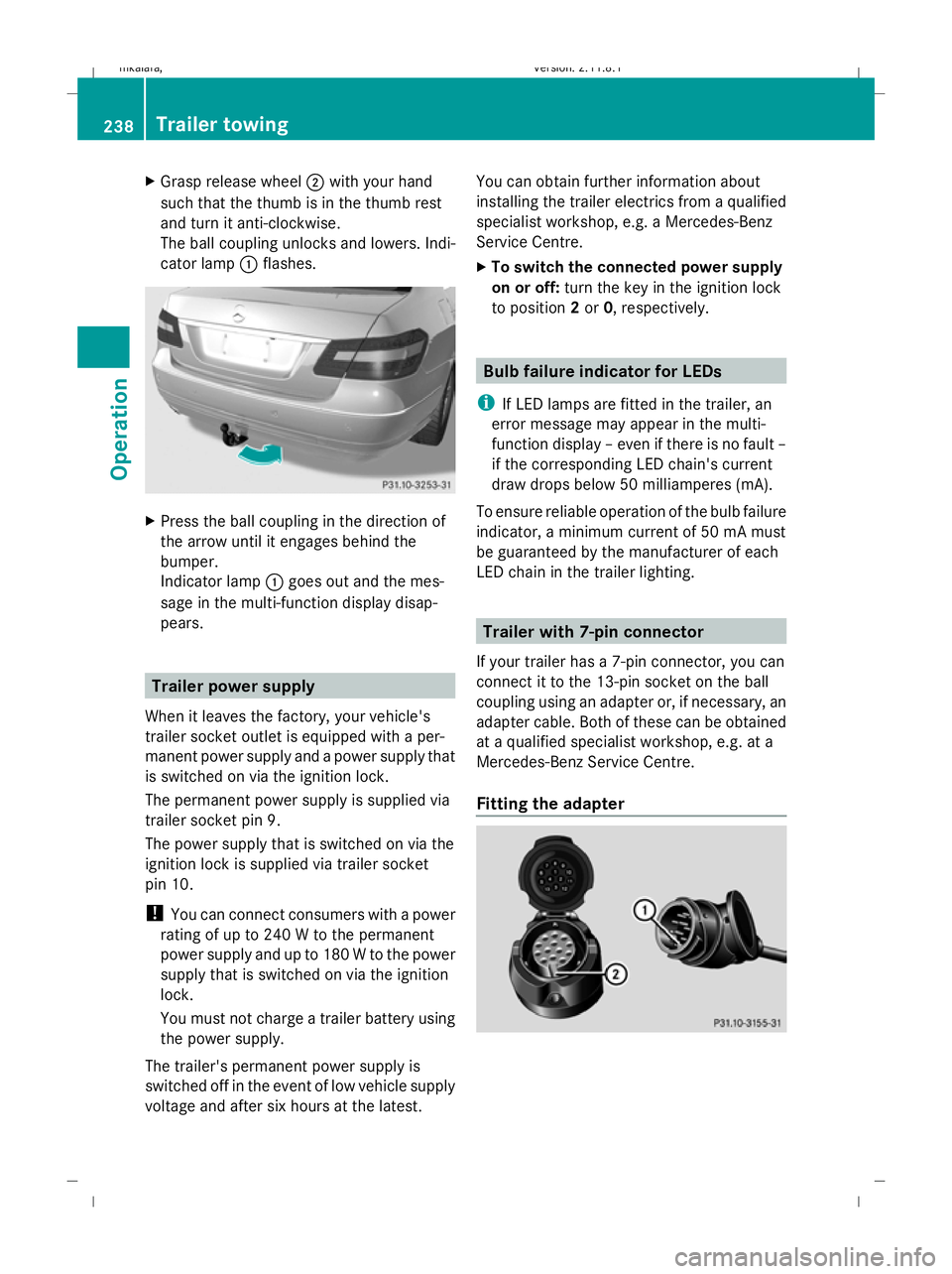
X
Grasp release wheel ;with your hand
such that the thumb is in the thumb rest
and turn it anti-clockwise.
The ball coupling unlocks and lowers. Indi-
cator lamp :flashes. X
Press the ball coupling in the direction of
the arrow until it engages behind the
bumper.
Indicator lamp :goes out and the mes-
sage in the multi-function display disap-
pears. Trailer power supply
When it leaves the factory, your vehicle's
trailer socket outlet is equipped with a per-
manent power supply and a power supply that
is switched on via the ignition lock.
The permanent power supply is supplied via
trailer socket pin 9.
The power supply that is switched on via the
ignition lock is supplied via trailer socket
pin 10.
! You can connect consumers with a power
rating of up to 240 W to the permanent
power supply and up to 180 W to the power
supply that is switched on via the ignition
lock.
You must not charge a trailer battery using
the power supply.
The trailer's permanent power supply is
switched off in the event of low vehicle supply
voltage and after six hours at the latest. You can obtain further information about
installing the trailer electrics from a qualified
specialist workshop, e.g. a Mercedes-Benz
Service Centre.
X
To switch the connected power supply
on or off: turn the key in the ignition lock
to position 2or 0, respectively. Bulb failure indicator for LEDs
i If LED lamps are fitted in the trailer, an
error message may appear in the multi-
function display – even if there is no fault –
if the corresponding LED chain's current
draw drops below 50 milliamperes (mA).
To ensure reliable operation of the bulb failure
indicator, a minimum current of 50 mA must
be guaranteed by the manufacturer of each
LED chain in the trailer lighting. Trailer with 7-pin connector
If your trailer has a 7-pin connector, you can
connect it to the 13-pin socket on the ball
coupling using an adapter or, if necessary, an
adapter cable. Both of these can be obtained
at a qualified specialist workshop, e.g. at a
Mercedes-Benz Service Centre.
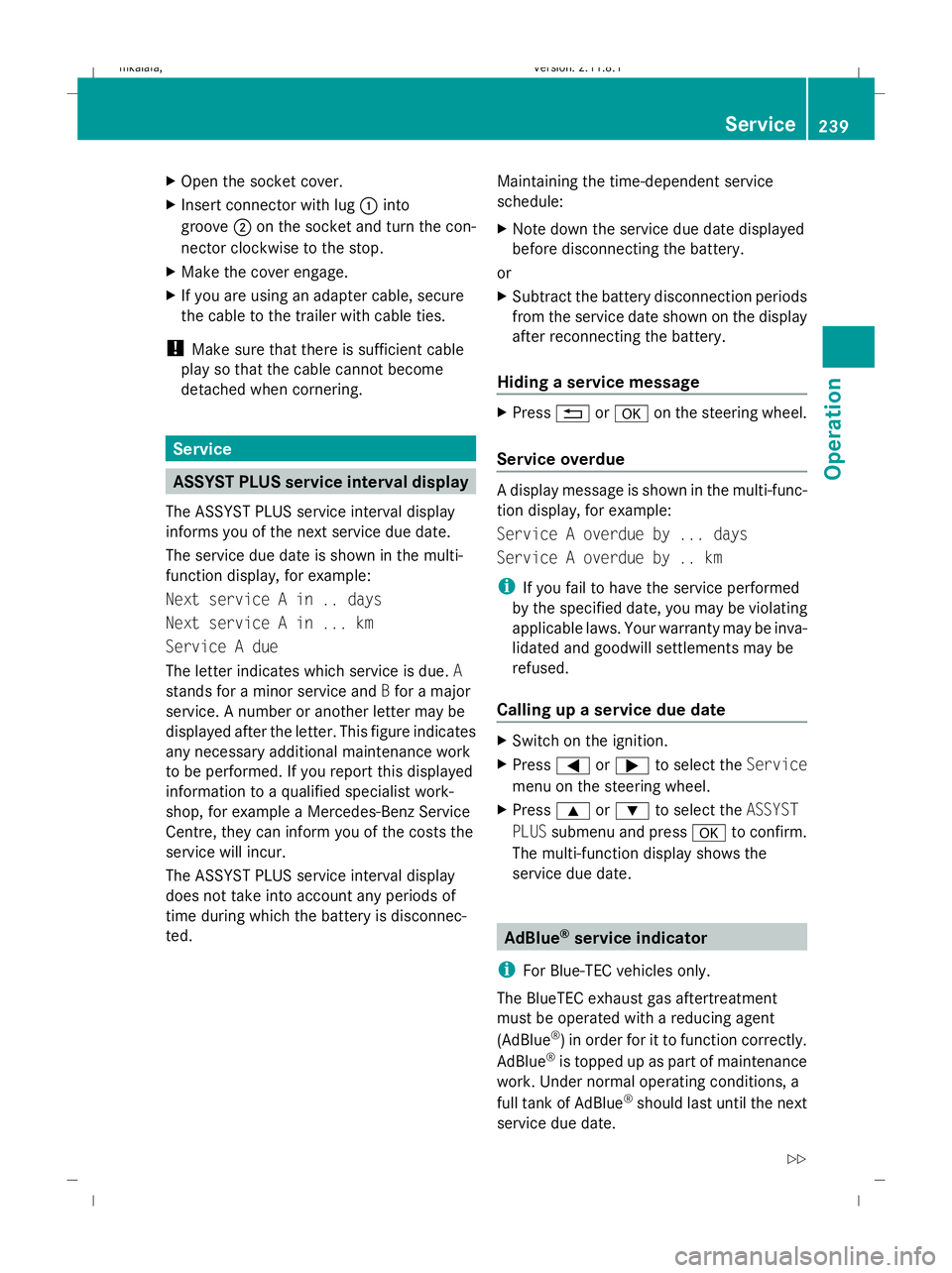
Fitting the adapter 238
Trailer towingOperation
212_AKB; 2; 4, en-GB
mkalafa
,V ersion: 2.11.8.1
2009-05-05T14:17:16+02:00 - Seite 238
Dateiname: 6515346702_buchblock.pdf; erzeugt am 07. May 2009 14:17:01; WK
Page 242 of 373

X
Open the socket cover.
X Insert connector with lug :into
groove ;on the socket and turn the con-
nector clockwise to the stop.
X Make the cover engage.
X If you are using an adapter cable, secure
the cable to the trailer with cable ties.
! Make sure that there is sufficient cable
play so that the cable cannot become
detached when cornering. Service
ASSYST PLUS service interval display
The ASSYST PLUS service interval display
informs you of the next service due date.
The service due date is shown in the multi-
function display, for example:
Next service A in .. days
Next service A in ... km
Service A due
The letter indicates which service is due. A
stands for a minor service and Bfor a major
service. A number or another letter may be
displayed after the letter. This figure indicates
any necessary additional maintenance work
to be performed. If you report this displayed
information to a qualified specialist work-
shop, for example a Mercedes-Benz Service
Centre, they can inform you of the costs the
service will incur.
The ASSYST PLUS service interval display
does not take into account any periods of
time during which the battery is disconnec-
ted. Maintaining the time-dependent service
schedule:
X
Note down the service due date displayed
before disconnecting the battery.
or
X Subtract the battery disconnection periods
from the service date shown on the display
after reconnecting the battery.
Hiding a service message X
Press %ora on the steering wheel.
Service overdue A display message is shown in the multi-func-
tion display, for example:
Service A overdue by ... days
Service A overdue by .. km
i
If you fail to have the service performed
by the specified date, you may be violating
applicable laws. Your warranty may be inva-
lidated and goodwill settlements may be
refused.
Calling up a service due date X
Switch on the ignition.
X Press =or; to select the Service
menu on the steering wheel.
X Press 9or: to select the ASSYST
PLUS submenu and press ato confirm.
The multi-function display shows the
service due date. AdBlue
®
service indicator
i For Blue-TEC vehicles only.
The BlueTEC exhaust gas aftertreatment
must be operated with a reducing agent
(AdBlue ®
) in order for it to function correctly.
AdBlue ®
is topped up as part of maintenance
work. Under normal operating conditions, a
full tank of AdBlue ®
should last until the next
service due date. Service
239Operation
212_AKB; 2; 4, en-GB
mkalafa, Version: 2.11.8.1 2009-05-05T14:17:16+02:00 - Seite 239 Z
Dateiname: 6515346702_buchblock.pdf; erzeugt am 07. May 2009 14:17:01; WK