2009 MERCEDES-BENZ E-CLASS SALOON key
[x] Cancel search: keyPage 324 of 373

right-hand side when viewed in the direction
of travel.
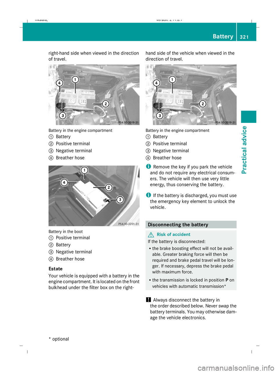
Battery in the engine compartment
:
Battery
; Positive terminal
= Negative terminal
? Breather hose Battery in the boot
:
Positive terminal
; Battery
= Negative terminal
? Breather hose
Estate
Your vehicle is equipped with a battery in the
engine compartment. It is located on the front
bulkhead under the filter box on the right- hand side of the vehicle when viewed in the
direction of travel. Battery in the engine compartment
:
Battery
; Positive terminal
= Negative terminal
? Breather hose
i Remove the key if you park the vehicle
and do not require any electrical consum-
ers. The vehicle will then use very little
energy, thus conserving the battery.
i If the battery is discharged, you must use
the emergency key element to unlock the
vehicle. Disconnecting the battery
G
Risk of accident
If the battery is disconnected:
R the brake boosting effect will not be avail-
able. Greater braking force will then be
required and brake pedal travel will be lon-
ger. If necessary, depress the brake pedal
with maximum force.
R the transmission is locked in position Pon
vehicles with automatic transmission*
! Always disconnect the battery in
the order described below. Never swap the
battery terminals. You may otherwise dam-
age the vehicle electronics. Battery
321Practical advice
* optional
212_AKB; 2; 4, en-GB
mkalafa,
Version: 2.11.8.1 2009-05-05T14:17:16+02:00 - Seite 321 Z
Dateiname: 6515346702_buchblock.pdf; erzeugt am 07. May 2009 14:17:25; WK
Page 325 of 373

X
Firmly depress the parking brake and on
vehicles with automatic transmission*,
shift the transmission to position P.
X Switch off all electrical consumers (e.g.
radio, blower, etc.).
X Turn the key to 0(Y page 75) in the ignition
lock and remove it or make sure that no
ignition position has been selected with
KEYLESS GO*. In the instrument cluster, all
of the indicator lamps must be out.
X Vehicles with the battery in the engine
compartment: open the bonnet.
X Vehicles with the battery in the boot:
open the boot. X
Vehicles with a battery in the engine
compartment: release and remove
clamps ;on filter box :.
X Remove the negative terminal clamp from
the battery.
X Remove the cover from the positive termi-
nal clamp.
X Remove the positive terminal clamp from
the battery.
X Disconnect the breather hose. Removing the battery
X Disconnect the battery ( Ypage 321).
X Loosen the bolt which holds the battery in
place.
X Remove the battery. Charging and fitting the battery
G
Risk of injury
Battery acid is caustic. Avoid contact with the
skin, eyes or clothing.
Charging the battery G
Risk of injury
Only charge the battery in a well-ventilated
area. As the battery is being charged, gases
can escape and generate minor explosions.
This could injure you and other persons or
cause damage to the paintwork or acid cor-
rosion on the vehicle.
You can obtain information about battery
chargers which allow the battery to be
charged while still installed from a qualified
specialist workshop, e.g. a Mercedes-Benz
Service Centre. G
Risk of injury
There is a risk of acid burns during the charg-
ing process due to the gases which escape
from the battery. Do not lean over the battery
during the charging process.
! Only charge the installed battery with a
battery charger which has been tested and
approved by Mercedes-Benz. These battery
chargers allow the battery to be charged
while still installed.
! Only use battery chargers with a maxi-
mum charging voltage of 14.8 V.
! Only charge the battery using the jump-
start connection point.
X Vehicles with the battery in the engine
compartment: open the bonnet.
X Vehicles with the battery in the boot:
open the boot.
X Connect the battery charger by its positive
terminal and earth point in the same order
as when connecting the donor battery in 322
BatteryPractical advice
* optional
212_AKB; 2; 4, en-GB
mkalafa
,V ersion: 2.11.8.1
2009-05-05T14:17:16+02:00 - Seite 322
Dateiname: 6515346702_buchblock.pdf; erzeugt am 07. May 2009 14:17:26; WK
Page 328 of 373

deactivate HOLD and Distronic Plus if the
vehicle is to be towed.
It is better to have the vehicle transported
than to have it towed.
When towing, observe the legal requirements
in all countries concerned.
! When towing, pull away slowly and
smoothly. If the tractive power is too high,
the vehicles could be damaged.
! Do not use the towing eye for recovery,
as this could damage the vehicle. If in
doubt, recover the vehicle with a crane.
! You may tow the vehicle for a maximum
of 50 km. A towing speed of 50 km/ hmust
not be exceeded.
For towing distances over 50 km, the entire
vehicle must be lifted up and transported.
! On vehicles with KEYLESS GO*, use the
key instead of the Start/Stop button. Turn
the key to position 2in the ignition lock and
shift the automatic transmission to N. Then
turn the key back to 0and leave it in the
ignition lock.
! Only secure the tow cable or towing bar
to the towing eyes. You could otherwise
damage the vehicle.
R Vehicles with an automatic transmission*
must not be tow-started.
R Vehicles with 4MATIC* must not be towed
with the front or rear axle raised.
R If you are towing the vehicle over a longer
distance, this must be done with the rear
axle raised.
R The ignition must be switched off if you are
towing the vehicle with the rear axle raised.
Otherwise, intervention by ESP ®
could
damage the brake system.
R If the vehicle has suffered transmission
damage, only tow it with the propeller shaft
disconnected. R
If the engine does not start, try jump-start-
ing it (Y page 323).
R If it is not possible to jump-start the vehicle,
have it towed to the nearest qualified spe-
cialist workshop, e.g. a Mercedes-Benz
Service Centre.
R The automatic transmission must be in
position Nwhen the vehicle is being towed.
R Before towing the vehicle, make sure that
the battery is connected and charged. Oth-
erwise:
-you cannot switch on the ignition.
- you cannot shift the transmission to posi-
tion Non vehicles with automatic trans-
mission*.
- you have no support when braking.
i Switch off the automatic locking feature
before the vehicle is towed (Y page 134).
Otherwise, you could be locked out when
pushing or towing the vehicle. Fitting the towing eye
Vehicles with a trailer tow hitch*: if you
intend to use the vehicle for towing, fold out
the ball coupling and connect the towbar
(Y page 234) to this. Towing and tow-starting
325Practical advice
* optional
212_AKB; 2; 4, en-GB
mkalafa,
Version: 2.11.8.1 2009-05-05T14:17:16+02:00 - Seite 325 Z
Dateiname: 6515346702_buchblock.pdf; erzeugt am 07. May 2009 14:17:27; WK
Page 329 of 373

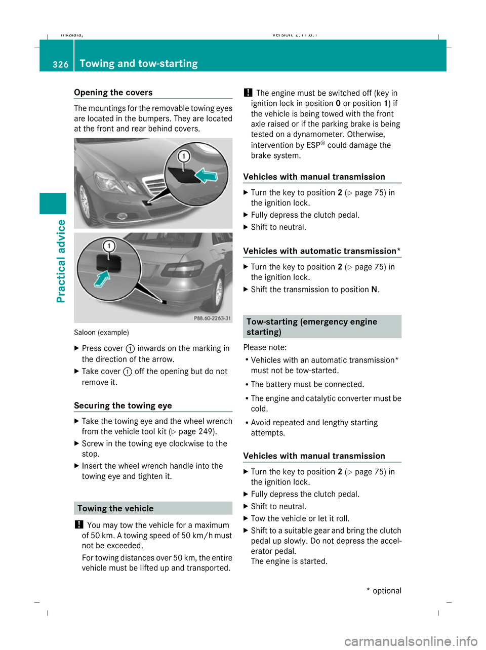
Opening the covers
The mountings for the removable towing eyes
are located in the bumpers. They are located
at the front and rear behind covers. Saloon (example)
X
Press cover :inwards on the marking in
the direction of the arrow.
X Take cover :off the opening but do not
remove it.
Securing the towing eye X
Take the towing eye and the wheel wrench
from the vehicle tool kit (Y page 249).
X Screw in the towing eye clockwise to the
stop.
X Insert the wheel wrench handle into the
towing eye and tighten it. Towing the vehicle
! You may tow the vehicle for a maximum
of 50 km. A towing speed of 50 km/hm ust
not be exceeded.
For towing distances over 50 km, the entire
vehicle must be lifted up and transported. !
The engine must be switched off (key in
ignition lock in position 0or position 1) if
the vehicle is being towed with the front
axle raised or if the parking brake is being
tested on a dynamometer. Otherwise,
intervention by ESP ®
could damage the
brake system.
Vehicles with manual transmission X
Turn the key to position 2(Y page 75) in
the ignition lock.
X Fully depress the clutch pedal.
X Shift to neutral.
Vehicles with automatic transmission* X
Turn the key to position 2(Y page 75) in
the ignition lock.
X Shift the transmission to position N. Tow-starting (emergency engine
starting)
Please note:
R Vehicles with an automatic transmission*
must not be tow-started.
R The battery must be connected.
R The engine and catalytic converter must be
cold.
R Avoid repeated and lengthy starting
attempts.
Vehicles with manual transmission X
Turn the key to position 2(Y page 75) in
the ignition lock.
X Fully depress the clutch pedal.
X Shift to neutral.
X Tow the vehicle or let it roll.
X Shift to a suitable gear and bring the clutch
pedal up slowly. Do not depress the accel-
erator pedal.
The engine is started. 326
Towing and tow-startingPractical advice
* optional
212_AKB; 2; 4, en-GB
mkalafa,
Version: 2.11.8.1 2009-05-05T14:17:16+02:00 - Seite 326
Dateiname: 6515346702_buchblock.pdf; erzeugt am 07. May 2009 14:17:28; WK
Page 330 of 373

Removing the towing eye
X Take the wheel wrench from the vehicle
tool kit (Y page 249).
X Insert the wheel wrench handle into the
towing eye and turn it anti-clockwise.
X Unscrew the towing eye.
X Replace the cover and press it until it
engages.
X Return the towing eye and the wheel
wrench to the vehicle tool kit. Transporting the vehicle
The towing eyes or trailer coupling* can be
used to pull the vehicle onto a trailer or trans-
porter if you wish to transport it.
! Only secure the vehicle by the wheels or
wheel rims, not by parts of the vehicle such
as axle or steering components. Otherwise,
the vehicle could be damaged.
Vehicles with manual transmission X
Shift to neutral.
Vehicles with automatic transmission* X
Turn the key to position 2(Y page 75) in
the ignition lock.
X Move the transmission to position N.Fuses
Notes on changing fuses
The fuses in your vehicle serve to close down
faulty circuits. If a fuse blows, all the compo-
nents on the circuit and their functions will
fail.
Blown fuses must be replaced with fuses of
the same rating, which you can recognise by
the colour and value. The fuse ratings are lis-
ted in the fuse allocation chart. A Mercedes- Benz Service Centre will be happy to advise
you. G
Risk of fire
Only use fuses that have been approved for
Mercedes-Benz vehicles and which have the
required fuse rating for the systems con-
cerned. Do not attempt to repair or bridge
faulty fuses. A circuit overload could other-
wise cause a fire. Have the cause traced and
rectified at a qualified specialist workshop,
e.g. a Mercedes-Benz Service Centre.
If the newly inserted fuse also blows, have the
cause traced and rectified at a qualified spe-
cialist workshop, e.g. a Mercedes-Benz
Service Centre.
! Only use fuses that have been approved
for Mercedes-Benz vehicles and which
have the correct fuse rating for the system
concerned. Otherwise, components or sys-
tems could be damaged.
The fuses are located in various fuse boxes:
R fuse box in the engine compartment on the
driver's side
R fuse box in the boot/luggage compartment
on the right-hand side of the vehicle
Fuse allocation chart The fuse allocation chart is located with the
vehicle tool kit (Y
page 249) in the stowage
compartment under the boot/luggage com-
partment floor. Before changing a fuse
X Park the vehicle.
X Switch off all electrical consumers.
X Remove the key from the ignition lock. Fuse box in the engine compartment
X Make sure that the windscreen wipers are
turned off. Fuses
327Practical advice
* optional
212_AKB; 2; 4, en-GB
mkalafa
,V ersion: 2.11.8.1
2009-05-05T14:17:16+02:00 - Seite 327 Z
Dateiname: 6515346702_buchblock.pdf; erzeugt am 07. May 2009 14:17:28; WK
Page 331 of 373

G
Risk of injury
Make sure that the windscreen wipers are
turned off and the key is pulled out of the igni-
tion lock before you open the cover of the fuse
box. Otherwise, the windscreen wipers and
the wiper rods above the cover could be set
in motion. This could lead to you or others
being injured by the wiper rods.
X To open: open the bonnet (Y page 219). X
Remove moisture from the fuse box using
a dry cloth.
X Unclip lines ;from the lid.
X Move aside lines ;. Route the lines behind
connection =to do this.
X Open clamps :and unhook the corre-
sponding wire straps at the bottom.
X Lift off the fuse box cover towards the front
of the vehicle.
X To close: check whether the rubber seal is
positioned correctly in the lid.
X Insert the lid into the bracket at the rear of
the fuse box.
X Press the lid down and secure with
clamps :.
X Clip lines ;onto the lid.
X Close the bonnet (Y page 219). Fuse box in the boot (Saloon)
X To open: open the boot lid. X
Push down the top of cover :in the boot
and fold down the cover. Fuse box in the luggage compartment
(Estate)
X To open: open the tailgate. X
Pull handle :.
X Open the cover downwards.
X Fold trim ;forwards. 328
FusesPractical advice
212_AKB; 2; 4, en-GB
mkalafa
,V ersion: 2.11.8.1
2009-05-05T14:17:16+02:00 - Seite 328
Dateiname: 6515346702_buchblock.pdf; erzeugt am 07. May 2009 14:17:29; WK
Page 365 of 373

Country Radio type approval number MHz frequency
range
Slovenia Article 6 of Directive 1999/5/EC R&TTE
500-1/2005-437 9 May 05 27, 40, 433, 868
Spain 000438/2005, 000439/2005, 000440/2005
000441/2005, 000445/2005, 000446/2005
000447/2005 27, 40, 433, 868
South Africa 11 October 2005 27, 40, 433
Syria 279/4/14 / 05 March 06
Czech Republic General Licence GL-30/R/2000 Reg. No. 844 13
May 05 27, 40, 433
Turkey National Certification 23 July 07 433
Hungary Article 6 of Directive 1999/5/EC R&TTE18 May
05 27, 40, 433, 868
United Arab
Emirates 1623/5/10-2/26/76 433
Cyprus Article 6 of Directive 1999/5/EC R&TTE5 May 05 27, 40, 433, 868
24-GHz radar sensor system (country
overview)*
The 24 GHz radar sensor system requires
separate approval for each country. When
you are driving in a country in which the radar
sensor system is not approved, you must
deactivate the system using the on-board
computer (Y page 134). The current country
overview can be obtained from a Mercedes-
Benz Service Centre. The radar sensor system is automatically
deactivated near radio telescope facilities. If
Distronic Plus*, Blind Spot Assist* or PRE-
SAFE
®
Brake* are activated at this point, a
corresponding warning will appear in the
multi-function display to tell you that the
radar sensor system is being switched off.
BAS PLUS* is also no longer available. If the
deactivation does not occur automatically,
you must deactivate the radar sensor system
using the on-board computer (Y page 134).Country Radio telescope
facilities Geographic coordinates
(latitude/longitude) Distance to be
maintained from the facility Egypt – – –
Andorra – – –
Australia Parkes 32°59'59"S, 148°15'44" E 10 km
Narrabri 30°18'52"S, 149°32'56" E 10 km362
24-GHz radar sensor system (country overview)*Technical data
* optional
212_AKB; 2; 4, en-GB
mkalafa,
Version: 2.11.8.1 2009-05-05T14:17:16+02:00 - Seite 362
Dateiname: 6515346702_buchblock.pdf; erzeugt am 07. May 2009 14:17:38; WK
Page 368 of 373

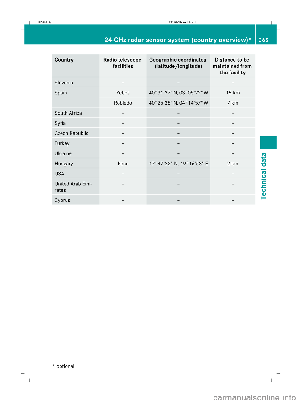
Country Radio telescope
facilities Geographic coordinates
(latitude/longitude) Distance to be
maintained from the facility Slovenia – – –
Spain Yebes 40°31'27" N, 03°05'22" W 15 km
Robledo 40°25'38" N, 04°14'57" W 7 km
South Africa – – –
Syria – – –
Czech Republic – – –
Turkey – – –
Ukraine – – –
Hungary Penc 47°47'22" N, 19°16'53" E 2 km
USA – – –
United Arab Emi-
rates – – –
Cyprus – – –24-GHz radar sensor system (country overview)*
365Technical data
* optional
212_AKB; 2; 4, en-GB
mkalafa,
Version: 2.11.8.1
2009-05-05T14:17:16+02:00 - Seite 365 Z
Dateiname: 6515346702_buchblock.pdf; erzeugt am 07. May 2009 14:17:39; WK