2009 LINCOLN TOWN CAR sensor
[x] Cancel search: sensorPage 119 of 280
The SRS consists of the following items:
•Driver and passenger airbag modules (which include the inflators and
airbags)
•safety belt pretensioners
•Front passenger sensing system
•“Passenger airbag off” or “pass airbag off” indicator lamp. Refer to
Front passenger sensing systemlater in this chapter.
•Driver and passenger side airbags
•One or more impact and safing sensors
•A readiness light and tone
•A diagnostic module
•The electrical wiring which connects the components
The diagnostic module monitors its own internal circuits as well as the
supplemental airbag electrical system wiring (including the impact
sensors), the system wiring, the airbag system readiness light, the airbag
back up power and the airbag ignitors.
WARNING:Several air bag system components get hot after
inflation. Do not touch them after inflation.
WARNING:If the air bag has deployed,the air bag will not
function again and must be replaced immediately.If the air
bag is not replaced, the unrepaired area will increase the risk of injury
in a collision.
WARNING:If the safety belt pretensioners deploy in an
accident, they will not function again ( belt will not extract or
retract) and must be replaced immediately. Failure to replace the
retractor assemblies will increase the risk of injury.
Front passenger sensing system
The front passenger sensing system is designed to meet the regulatory
requirements of Federal Motor Vehicle Safety Standard (FMVSS) 208
and is designed to disable (will not inflate) the front passenger’s frontal
airbag under certain conditions.
The front passenger sensing system works with sensors that are part of
the front passenger’s seat and safety belt. The sensors are designed to
2009 Town Car(tow)
Owners Guide, 1st Printing
USA(fus)
Seating and Safety Restraints
119
Page 125 of 280
WARNING:Do not use accessory seat covers. The use of
accessory seat covers may prevent the deployment of the side
airbags and increase the risk of injury in an accident.
WARNING:Do not lean your head on the door. The side airbag
could injure you as it deploys from the side of the seatback.
WARNING:Do not attempt to service, repair, or modify the
airbag SRS, its fuses or the seat cover on a seat containing an
airbag. See your authorized dealer.
WARNING:All occupants of the vehicle should always wear
their safety belts even when an airbag SRS is provided.
How does the side airbag system work?
The design and development of the
side airbag system included
recommended testing procedures
that were developed by a group of
automotive safety experts known as
the Side Airbag Technical Working
Group. These recommended testing
procedures help reduce the risk of
injuries related to the deployment of
side airbags.
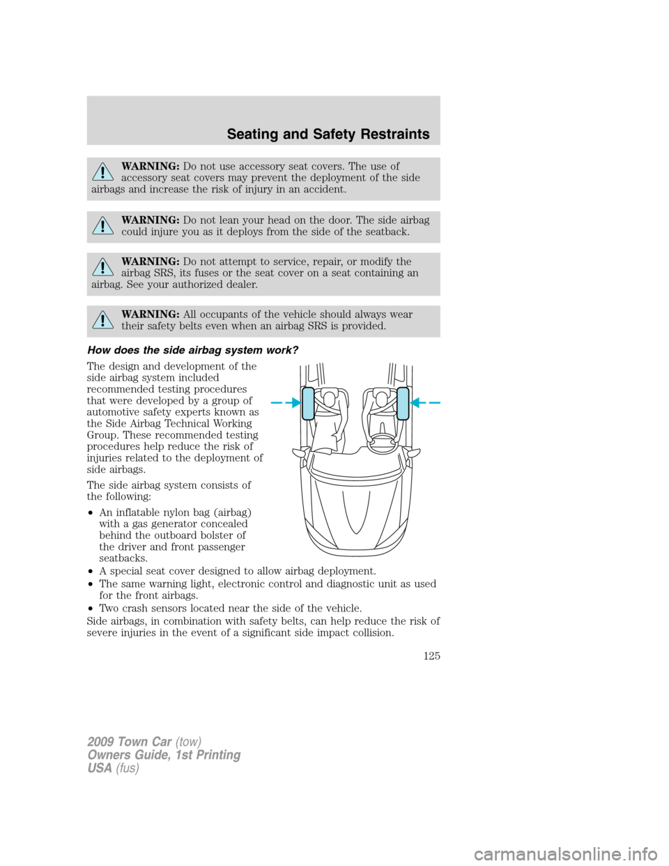
The side airbag system consists of
the following:
•An inflatable nylon bag (airbag)
with a gas generator concealed
behind the outboard bolster of
the driver and front passenger
seatbacks.
•A special seat cover designed to allow airbag deployment.
•The same warning light, electronic control and diagnostic unit as used
for the front airbags.
•Two crash sensors located near the side of the vehicle.
Side airbags, in combination with safety belts, can help reduce the risk of
severe injuries in the event of a significant side impact collision.
2009 Town Car(tow)
Owners Guide, 1st Printing
USA(fus)
Seating and Safety Restraints
125
Page 126 of 280
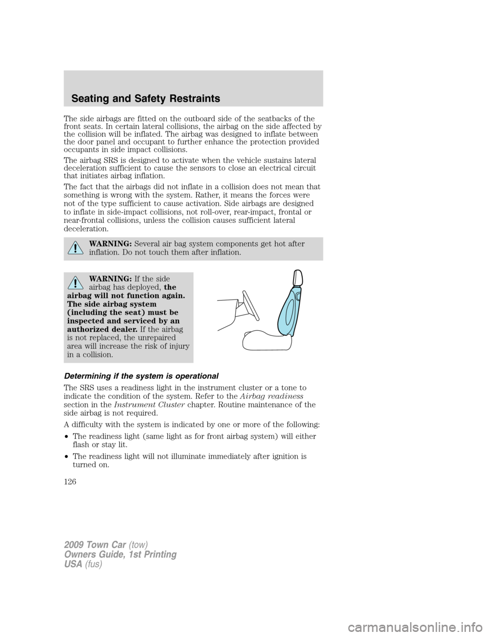
The side airbags are fitted on the outboard side of the seatbacks of the
front seats. In certain lateral collisions, the airbag on the side affected by
the collision will be inflated. The airbag was designed to inflate between
the door panel and occupant to further enhance the protection provided
occupants in side impact collisions.
The airbag SRS is designed to activate when the vehicle sustains lateral
deceleration sufficient to cause the sensors to close an electrical circuit
that initiates airbag inflation.
The fact that the airbags did not inflate in a collision does not mean that
something is wrong with the system. Rather, it means the forces were
not of the type sufficient to cause activation. Side airbags are designed
to inflate in side-impact collisions, not roll-over, rear-impact, frontal or
near-frontal collisions, unless the collision causes sufficient lateral
deceleration.
WARNING:Several air bag system components get hot after
inflation. Do not touch them after inflation.
WARNING:If the side
airbag has deployed,the
airbag will not function again.
The side airbag system
(including the seat) must be
inspected and serviced by an
authorized dealer.If the airbag
is not replaced, the unrepaired
area will increase the risk of injury
in a collision.
Determining if the system is operational
The SRS uses a readiness light in the instrument cluster or a tone to
indicate the condition of the system. Refer to theAirbag readiness
section in theInstrument Clusterchapter. Routine maintenance of the
side airbag is not required.
A difficulty with the system is indicated by one or more of the following:
•The readiness light (same light as for front airbag system) will either
flash or stay lit.
•The readiness light will not illuminate immediately after ignition is
turned on.
2009 Town Car(tow)
Owners Guide, 1st Printing
USA(fus)
Seating and Safety Restraints
126
Page 152 of 280
WARNING:When mounting replacement tires and wheels, you
should not exceed the maximum pressure indicated on the
sidewall of the tire to set the beads without additional precautions
listed below. If the beads do not seat at the maximum pressure
indicated, re-lubricate and try again.
When inflating the tire for mounting pressures up to 20 psi greater
than the maximum pressure on the tire sidewall, the following
precautions must be taken to protect the person mounting the tire:
1. Make sure that you have the correct tire and wheel size.
2. Lubricate the tire bead and wheel bead seat area again.
3. Stand at a minimum of 12 ft. (3.66 m) away from the tire wheel
assembly.
4. Use both eye and ear protection.
For a mounting pressure more than 20 psi greater than the maximum
pressure, a Ford Dealer or other tire service professional should do the
mounting.
Always inflate steel carcass tires with a remote air fill with the person
inflating standing at a minimum of 12 ft. (3.66 m) away from the tire
wheel assembly.
Important:Remember to replace the wheel valve stems when the road
tires are replaced on your vehicle.
It is recommended that the two front tires or two rear tires generally be
replaced as a pair.
The tire pressure sensors mounted in the wheels (if equipped) are not
designed to be used in aftermarket wheels.
The use of wheels or tires not recommended by Ford Motor Company
may affect the operation of your Tire Pressure Monitoring System (if
equipped).
If the TPMS indicator is flashing, your TPMS is malfunctioning. Your
replacement tire might be incompatible with your TPMS, or some
component of the TPMS may be damaged (if equipped).
Safety practices
Driving habits have a great deal to do with your tire mileage and safety.
•Observe posted speed limits
•Avoid fast starts, stops and turns
•Avoid potholes and objects on the road
2009 Town Car(tow)
Owners Guide, 1st Printing
USA(fus)
Tires, Wheels and Loading
152
Page 161 of 280
following two conditions: (1) This device may not cause harmful
interference, and (2) This device must accept any interference received,
including interference that may cause undesired operation.
WARNING:The Tire Pressure Monitoring System is NOT a
substitute for manually checking tire pressure. The tire pressure
should be checked periodically (at least monthly) using a tire gauge,
seeInflating your tiresin this chapter. Failure to properly maintain
your tire pressure could increase the risk of tire failure, loss of control,
vehicle rollover and personal injury.
Changing tires with TPMS
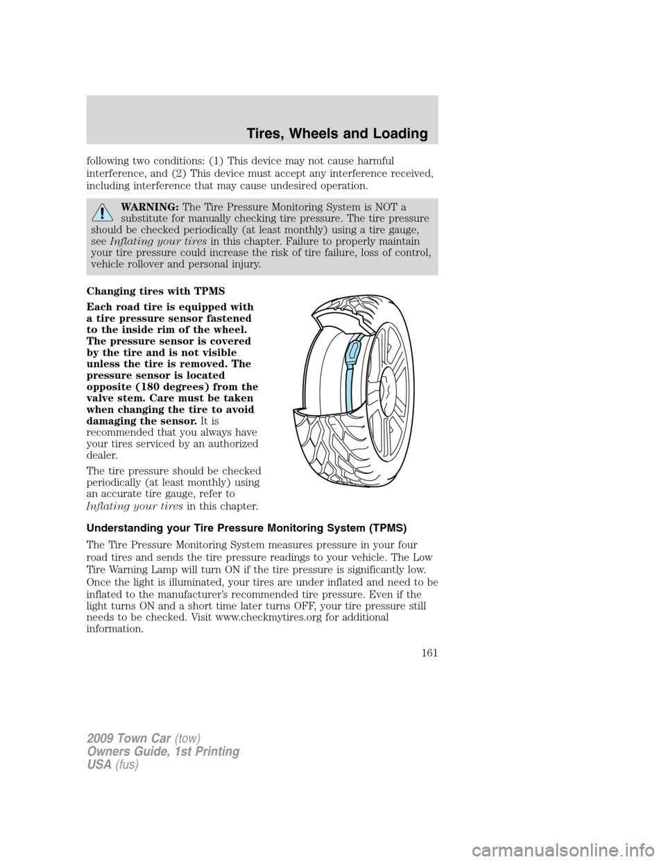
Each road tire is equipped with
a tire pressure sensor fastened
to the inside rim of the wheel.
The pressure sensor is covered
by the tire and is not visible
unless the tire is removed. The
pressure sensor is located
opposite (180 degrees) from the
valve stem. Care must be taken
when changing the tire to avoid
damaging the sensor.It is
recommended that you always have
your tires serviced by an authorized
dealer.
The tire pressure should be checked
periodically (at least monthly) using
an accurate tire gauge, refer to
Inflating your tiresin this chapter.
Understanding your Tire Pressure Monitoring System (TPMS)
The Tire Pressure Monitoring System measures pressure in your four
road tires and sends the tire pressure readings to your vehicle. The Low
Tire Warning Lamp will turn ON if the tire pressure is significantly low.
Once the light is illuminated, your tires are under inflated and need to be
inflated to the manufacturer’s recommended tire pressure. Even if the
light turns ON and a short time later turns OFF, your tire pressure still
needs to be checked. Visit www.checkmytires.org for additional
information.
2009 Town Car(tow)
Owners Guide, 1st Printing
USA(fus)
Tires, Wheels and Loading
161
Page 192 of 280
The radar sensor is located behind the rear bumper/fascia. Always
keep the rear bumper/fascia free from snow, ice and large
accumulations of dirt. These elements may cause the system to
operate inaccurately.
If the vehicle sustains damage to the rear bumper/fascia, leaving
it misaligned or bent, the sensing zone may be altered causing
inaccurate measurement of obstacles or false alarms.
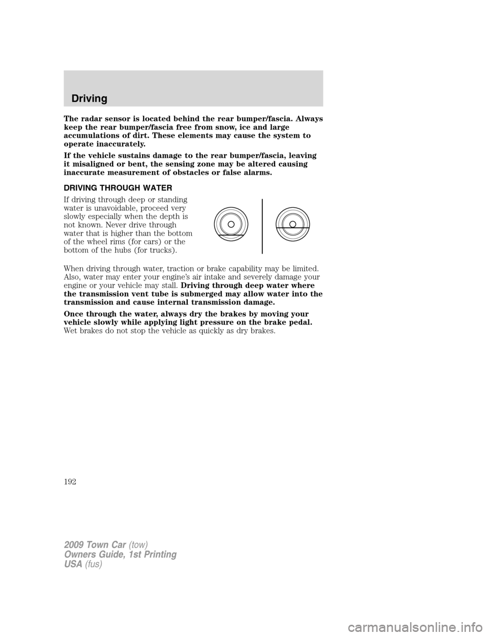
DRIVING THROUGH WATER
If driving through deep or standing
water is unavoidable, proceed very
slowly especially when the depth is
not known. Never drive through
water that is higher than the bottom
of the wheel rims (for cars) or the
bottom of the hubs (for trucks).
When driving through water, traction or brake capability may be limited.
Also, water may enter your engine’s air intake and severely damage your
engine or your vehicle may stall.Driving through deep water where
the transmission vent tube is submerged may allow water into the
transmission and cause internal transmission damage.
Once through the water, always dry the brakes by moving your
vehicle slowly while applying light pressure on the brake pedal.
Wet brakes do not stop the vehicle as quickly as dry brakes.
2009 Town Car(tow)
Owners Guide, 1st Printing
USA(fus)
Driving
192
Page 197 of 280
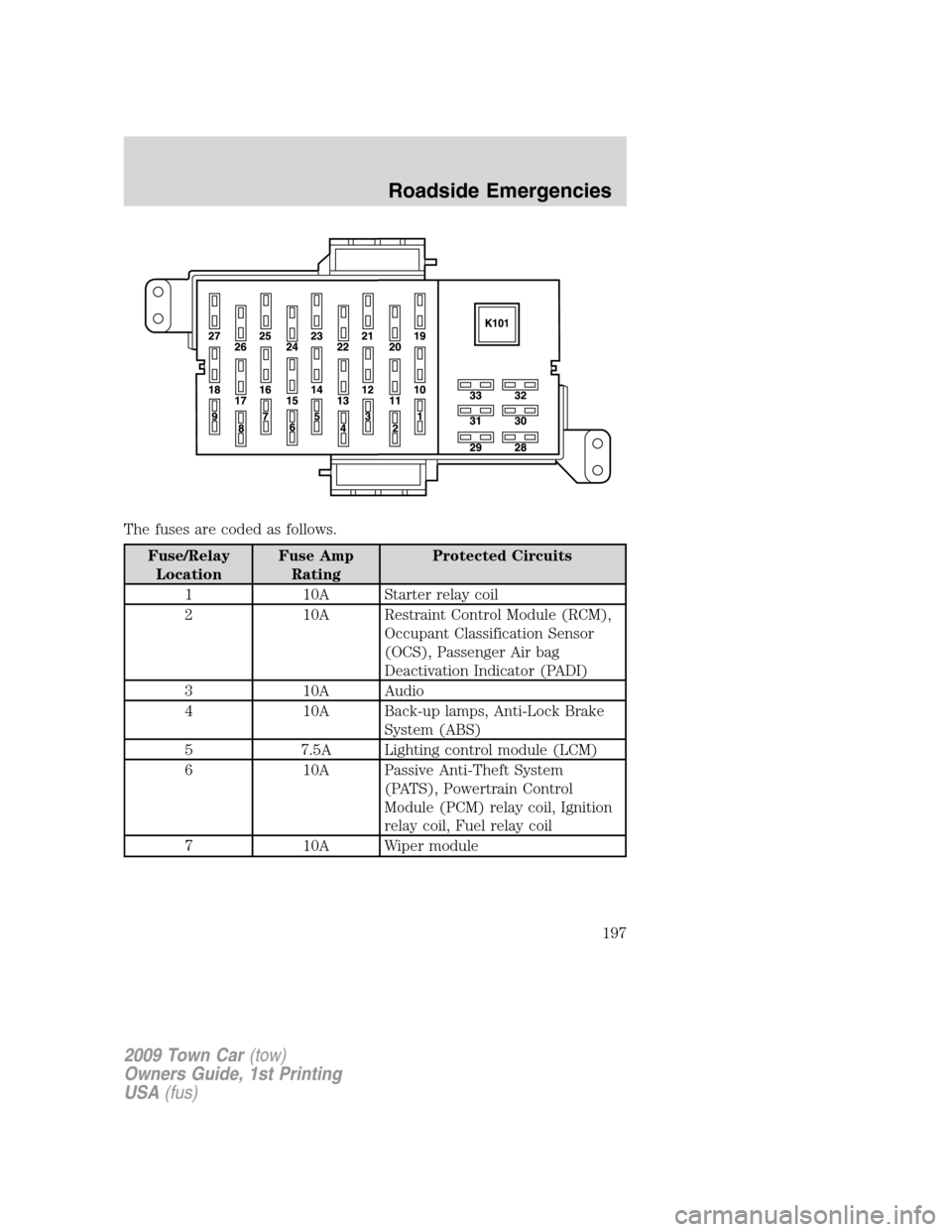
The fuses are coded as follows.
Fuse/Relay
LocationFuse Amp
RatingProtected Circuits
1 10A Starter relay coil
2 10A Restraint Control Module (RCM),
Occupant Classification Sensor
(OCS), Passenger Air bag
Deactivation Indicator (PADI)
3 10A Audio
4 10A Back-up lamps, Anti-Lock Brake
System (ABS)
5 7.5A Lighting control module (LCM)
6 10A Passive Anti-Theft System
(PATS), Powertrain Control
Module (PCM) relay coil, Ignition
relay coil, Fuel relay coil
7 10A Wiper module
2009 Town Car(tow)
Owners Guide, 1st Printing
USA(fus)
Roadside Emergencies
197
Page 201 of 280
Fuse/Relay
LocationFuse Amp
RatingProtected Circuits
13 10A* Rear air suspension module
(RASM)
14 20A* Stop lamp switch
15 15A* Lumbar, Fuel door
16 20A* Heated seats
17 – Not used
18 – Not used
19 15A* Injectors
20 15A* PCM
21 15A* Powertrain loads and sensors
22 — Not used
23 10A* Heated mirrors
24 – Not used
101 40A** Blower relay feed
102 50A** Cooling fan
103 50A** Instrument panel fuse box feed #1
104 50A** Instrument panel fuse box feed #2
105 30A** Starter relay feed
106 40A** ABS module (Pump)
107 40A** Rear defroster relay feed
108 40A** Power Decklid Module (PDM)
109 20A** ABS module (Valves)
110 30A** Wiper module
111 20A** Left rear power point
112 30A** RASM (Air compressor)
113 20A** Rear power point #2
114 20A** Instrument panel fuse box feed #3
115 20A** Rear cigar lighters
116 30A** Decklid pulldown module
117 20A** Cigar lighter
118 — Not used
2009 Town Car(tow)
Owners Guide, 1st Printing
USA(fus)
Roadside Emergencies
201