Page 156 of 506

Windshield Washers
To use the washer, pull the windshield wiper/washer
control lever toward you and hold it for as long as
washer spray is desired.
If you activate the washer while the wiper control is in
the delay range, the wipers will operate in low-speed for
two wipe cycles after releasing the lever and then resume
the intermittent interval previously selected.
If you activate the washer while the wiper control is in
the off position, the wipers will operate for two wipe
cycles and then turn off.
TILT STEERING COLUMN
This feature allows you to tilt the steering column
upward or downward. The tilt control handle is located
below the steering wheel at the end of the steering
column.To unlock the steering column, push the control handle
downward. To tilt the steering column, move the steering
wheel upward or downward as desired. To lock the
steering column in position, pull the control handle
upward until it is fully engaged.
Tilt Steering Control Handle
154 UNDERSTANDING THE FEATURES OF YOUR VEHICLE
Page 157 of 506
WARNING!
Do not adjust the steering wheel while driving. The
tilt adjustment must be locked while driving. Adjust-
ing the steering wheel while driving or driving
without the tilt adjustment locked could cause the
driver to lose control of the vehicle.
ELECTRONIC SPEED CONTROL — IF EQUIPPED
When engaged, the Electronic Speed Control takes over
the accelerator operation at speeds greater than 25 mph
(40 km/h).
The Electronic Speed Control lever is located on the right
side of the steering wheel.NOTE:
In order to ensure proper operation, the Elec-
tronic Speed Control System has been designed to shut
down if multiple Speed Control functions are operated
Electronic Speed Control Lever
UNDERSTANDING THE FEATURES OF YOUR VEHICLE 155
3
Page 205 of 506

maintain correct tire pressure, even if under-inflation has
not reached the level to trigger illumination of the TPMS
low tire pressure telltale.
Your vehicle has also been equipped with a TPMS
malfunction indicator to indicate when the system is not
operating properly. The TPMS malfunction indicator is
combined with the low tire pressure telltale. When the
system detects a malfunction, the telltale will flash for
approximately one minute and then remain continuously
illuminated. This sequence will continue upon subse-
quent vehicle start-ups as long as the malfunction exists.
When the malfunction indicator is illuminated, the sys-
tem may not be able to detect or signal low tire pressure
as intended. TPMS malfunctions may occur for a variety
of reasons, including the installation of replacement or
alternate tires or wheels on the vehicle that prevent the
TPMS from functioning properly. Always check the
TPMS malfunction telltale after replacing one or moretires or wheels on your vehicle, to ensure that the
replacement or alternate tires and wheels allow the TPMS
to continue to function properly.
CAUTION!
The TPMS has been optimized for the original
equipment tires and wheels. TPMS pressures and
warning have been established for the tire size
equipped on your vehicle. Undesirable system opera-
tion or sensor damage may result when using re-
placement equipment that is not of the same size,
type, and/or style. Aftermarket wheels can cause
sensor damage. Do not use tire sealant from a can, or
balance beads if your vehicle is equipped with a
TPMS, as damage to the sensors may result.
UNDERSTANDING YOUR INSTRUMENT PANEL 203
4
Page 209 of 506
. Before the pointer reaches the red area,
ease up on the accelerator to prevent engine damage.
16. 4WD LOW Indicator — I")
15. Tachometer
This gauge measures engine revolutions-per-minute
(RPM x 1000). Before the pointer reaches the red area,
ease up on the accelerator to prevent engine damage.
16. 4WD LOW Indicator — If EquippedThis light alerts the driver that the vehicle is in
the 4WD LOW mode. In this mode, the front
driveshaft and rear driveshaft are mechanically
locked together forcing the front and rear
wheels to rotate at the same speed.
17. Hill Descent Control Indicator — If Equipped The symbol indicates the status of the Hill
Descent Control (HDC) feature. The lamp will
be on solid when HDC is armed. HDC can only
be armed when the transfer case is in the “4WD
LOW” position and the vehicle speed is less then 30 mph (48 km/h). If these conditions are not met while attempt-
ing to use the HDC feature, the HDC indicator light will
flash on/off.
18. TOW/HAUL Indicator — If Equipped
This light will illuminate when selecting
TOW/HAUL. The TOW/HAUL button is lo-
cated on the gearshift bezel.
19. 4WD Indicator — Vehicles Equipped with
Command-Trac� This light alerts the driver that the vehicle is in
the four-wheel drive mode. In this mode, the
front driveshaft and rear driveshaft are me-
chanically locked together forcing the front and
rear wheels to rotate at the same speed.
UNDERSTANDING YOUR INSTRUMENT PANEL 207
4
Page 213 of 506

26. 4WD Indicator — Vehicles Equipped with
Selec-Trac�II
This light alerts the driver that the vehicle is in
the full-time four-wheel drive auto mode. In
this mode, the system operates with a normal
torque split of 42% front axle and 58% rear axle.
It can redirect up to 100% of torque to the front or rear
axle, if necessary.
27. Odometer/Trip Odometer
The odometer shows the total distance the vehicle has
been driven. The trip odometer shows individual trip
mileage. Refer to “Trip Odometer button” for additional
information.
NOTE: U.S. Federal regulations require upon transfer of
vehicle ownership, the seller certify the mileage the
vehicle has been driven. Therefore, if the odometer
reading is changed because of repair or replacement, be sure to keep a record of the reading before and after the
service so that the correct mileage can be determined.
Vehicle Warning Messages
When the appropriate conditions exist, messages such as
“door” (door ajar), “gATE” (liftgate ajar), “gLASS”
(flip-up glass ajar), “gASCAP” (fuel cap fault), “LoW
tirE” (low tire pressure), or “CHANgE OIL” will display
in the odometer.
LoW tirE
When the appropriate condition exists, the odometer
display will toggle between LoW and tirE for three
cycles.
NOTE:
If the instrument cluster is equipped with the
optional Electronic Vehicle Information Center (EVIC),
then most warnings will display in the EVIC.
UNDERSTANDING YOUR INSTRUMENT PANEL 211
4
Page 218 of 506

This system conveniently allows the driver to select a
variety of useful information by pressing the switches
mounted on the steering wheel. The EVIC consists of the
following:
•System Status
•Vehicle information warning message displays
•Tire Pressure Monitor System (if equipped)
•Personal Settings (Customer-Programmable Features)
•Compass display
•Outside temperature display
•Trip computer functions
•Navigation system screens (if equipped)
•Audio mode displayThe system allows the driver to select information by
pressing the following buttons mounted on the steering
wheel:
Press and release the MENU button and the
mode displayed will change between Trip
Functions, Navigation (if equipped), System
Status, Personal Settings.
Press the SCROLL button to scroll through Trip
Functions, Navigation (if equipped), System
Status Messages, and Personal Settings
(Customer-Programmable Features).
Press and release the COMPASS/TEMPERA-
TURE button to display one of eight compass
readings and the outside temperature.
MENUButton
SCROLL Button
216 UNDERSTANDING YOUR INSTRUMENT PANEL
Page 273 of 506
Operating Instructions — uconnect�phone (If
Equipped)
Refer to “uconnect� phone” in Section 3.
Operating Instructions — Video Entertainment
System (VES)™ (If Equipped)
Refer to separate “Video Entertainment System (VES)™
Guide.”
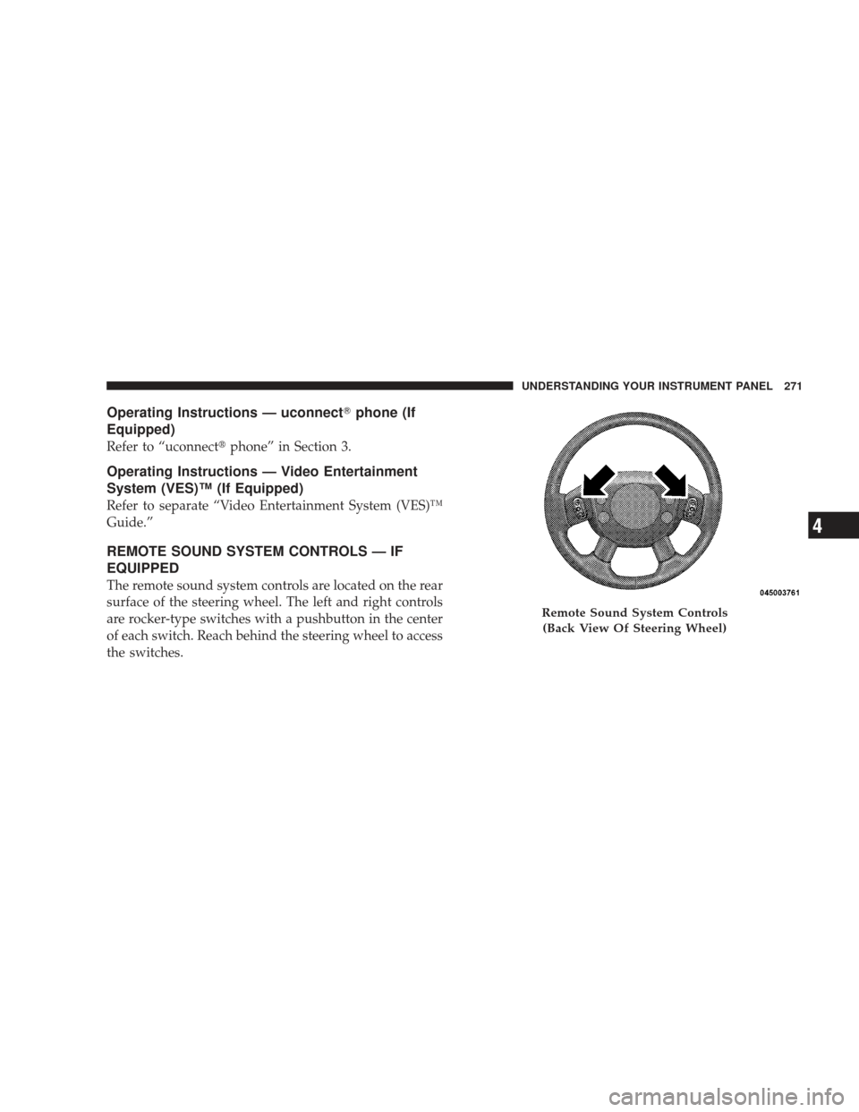
REMOTE SOUND SYSTEM CONTROLS — IF
EQUIPPED
The remote sound system controls are located on the rear
surface of the steering wheel. The left and right controls
are rocker-type switches with a pushbutton in the center
of each switch. Reach behind the steering wheel to access
the switches.
Remote Sound System Controls
(Back View Of Steering Wheel)
UNDERSTANDING YOUR INSTRUMENT PANEL 271
4
Page 289 of 506
STARTING AND OPERATING
CONTENTS
�Starting Procedures .................... 291
▫ Normal Starting ..................... 291
▫ Extreme Cold Weather (Below –20°F Or
–29°C) ............................ 291
▫ If Engine Fails To Start ................ 292
▫ After Starting ....................... 293
� Engine Block Heater — If Equipped ........ 293
� Automatic Transmission ................. 294
▫ Brake/Transmission Shift
Interlock System ..................... 295 ▫
Brake/Transmission Interlock Manual
Override .......................... 295
▫ 4–Speed Automatic Transmission ......... 296
� Four-Wheel Drive Operation ............. 302
▫ MP1522 Command-Trac� Transfer Case — If
Equipped .......................... 302
▫ MP3022 Selec-Trac II� Transfer Case — If
Equipped .......................... 308
� On-Road Driving Tips .................. 313
5