Page 76 of 521
▫General Information.................. 110
�Voice Recognition System (VR) —
If Equipped.......................... 110
▫Voice Recognition System (VR) Operation . . . 110
▫Commands........................ 112
▫Voice Training...................... 115
�Seats.............................. 115
▫Front Manual Seat Adjustment........... 115
▫Front Seat Adjustment — Recline......... 116
▫Manual Lumbar Support Adjustment...... 116
▫Eight-Way Driver’s Power Seat........... 117
▫Four-Way Passenger’s Power Seat — If
Equipped.......................... 117
▫Head Restraints..................... 118▫Front Heated Seats — If Equipped........ 118
▫Rear Heated Seats — If Equipped......... 120
▫60/40 Split Rear Seat.................. 122
�Driver Memory Seat — If Equipped........ 124
▫Setting Memory Positions And Linking
Remote Keyless Entry (RKE) Transmitter To
Memory........................... 125
▫Memory Position Recall................ 126
▫To Disable A RKE Transmitter Linked To
Memory........................... 127
▫Easy Entry/Exit Seat.................. 128
�To Open And Close The Hood............ 129
�Lights............................. 130
▫Multifunction Lever.................. 130
74 UNDERSTANDING THE FEATURES OF YOUR VEHICLE
Page 118 of 521
Front Seat Adjustment — Recline
To adjust the seatback, lift the lever located on the
outboard side of the seat, lean back, and release the lever
at the desired position. To return the seatback, lift the
lever, lean forward, and release the lever.
WARNING!
•Do not ride with the seatback reclined so that the
seat belt is no longer resting against your chest. In
a collision, you could slide under the seat belt and
be seriously or even fatally injured. Use the re-
cliner only when the vehicle is parked.
•It is extremely dangerous to ride in a cargo area,
inside or outside of a vehicle. In a collision, people
riding in these areas are more likely to be seri-
ously injured or killed.
(Continued)
WARNING! (Continued)
•Do not allow people to ride in any area of your
vehicle that is not equipped with seats and seat
belts.
•Be sure everyone in your vehicle is in a seat and
using a seat belt properly.
Manual Lumbar Support Adjustment
The manual lumbar support adjustment lever is located
on the right side of the driver’s seat (all models) and on
the left side of the passenger’s seat (if equipped). Moving
the lumbar control lever forward and rearward will
increase or decrease the lumbar support.
116 UNDERSTANDING THE FEATURES OF YOUR VEHICLE
Page 119 of 521
Eight-Way Driver’s Power Seat
The driver’s power seat switches are located on the
outboard side of the driver’s seat lower side trim. The
bottom switch controls up/down, forward/rearward,
and tilt adjustment. The top switch controls the seatback
recline adjustment.
Four-Way Passenger’s Power Seat — If Equipped
The front passenger’s power seat switches are located on
the outboard side of the passenger seat lower side trim.
The bottom switch controls forward/rearward adjust-
ment. The top switch controls the seatback recline adjust-
ment.
Manual Lumbar ControlPower Seat Switches
UNDERSTANDING THE FEATURES OF YOUR VEHICLE 117
3
Page 120 of 521
NOTE:The four-way seat does not have an up/down
adjustment.
Head Restraints
Head restraints can reduce the risk of whiplash injury in
the event of impact from the rear. Adjustable head
restraints should be adjusted so that the upper edge is as
High as practical. The head restraints have a locking
button which must be pushed in to lower the head
restraint to all positions. The restraints may be raised
without pushing in the button.
Front Heated Seats — If Equipped
The front driver and passenger seats are heated. The
controls for each heater are located near the bottom
center of the instrument panel (below the heater/air
conditioning controls). The heaters provide the same
average heat level for both the cushion and the seatback.
Adjustable Head Restraints
118 UNDERSTANDING THE FEATURES OF YOUR VEHICLE
Page 130 of 521
Easy Entry/Exit Seat
This feature provides automatic driver’s seat positioning
which will enhance driver mobility out of and into the
vehicle.
There are two possible Easy Entry/Exit adjustments
available:
•The seat cushion will move rearward approximately
2.5 in (60 mm), if the starting position of the seat is
greater than or equal to 2.67 in (68 mm) forward of the
rear seat stop when the key is removed from the
ignition switch. The seat will then move forward
approximately 2.5 in (60 mm) when the key is placed
into the ignition and turned out of the LOCK position.
•The seat will move to the position located 0.3 in
(8 mm) forward of the rear stop if the starting position
is between 0.9 to 2.67 in (23 to 68 mm) forward of the
rear stop when the key is removed from the ignition
switch. The seat will move forward to the memory/driving position when the key is placed into the
ignition, and turned out of the LOCK position toward
the ACC/ON position.
The Easy Entry/Exit feature will be automatically dis-
abled if the seat is already positioned closer than 0.9 in
(23 mm) forward of the rear stop. At this position, there
is no benefit to the driver by moving the seat for Easy
Exit/Entry.
Each stored memory setting will have an associated Easy
Entry/Exit position.
NOTE:The Easy Entry/Exit feature is not enabled
when the vehicle is delivered from the factory. The Easy
Entry/Exit feature is enabled (or later disabled) through
the programmable features in the Electronic Vehicle
Information Center (EVIC). Refer to�Electronic Vehicle
Information Center (EVIC) — Customer-Programmable
Features�in Section 4 for more information.
128 UNDERSTANDING THE FEATURES OF YOUR VEHICLE
Page 145 of 521
the steering wheel outward or push it inward as desired.
To lock the steering column in position, push the control
handle upward until fully engaged.
WARNING!
Do not adjust the steering wheel while driving. The
telescoping adjustment must be locked while driv-
ing. Adjusting the steering wheel while driving or
driving without the telescoping adjustment locked
could cause the driver to lose control of the vehicle.
ADJUSTABLE PEDALS — IF EQUIPPED
This feature allows both the brake and accelerator pedals
to move toward or away from the driver to provide
improved position with the steering wheel. The adjust-
able pedal system is designed to allow a greater range of
driver comfort for steering wheel tilt and seat position.
The position of the brake and accelerator pedals can beadjusted without compromising safety or comfort in
actuating the pedals.
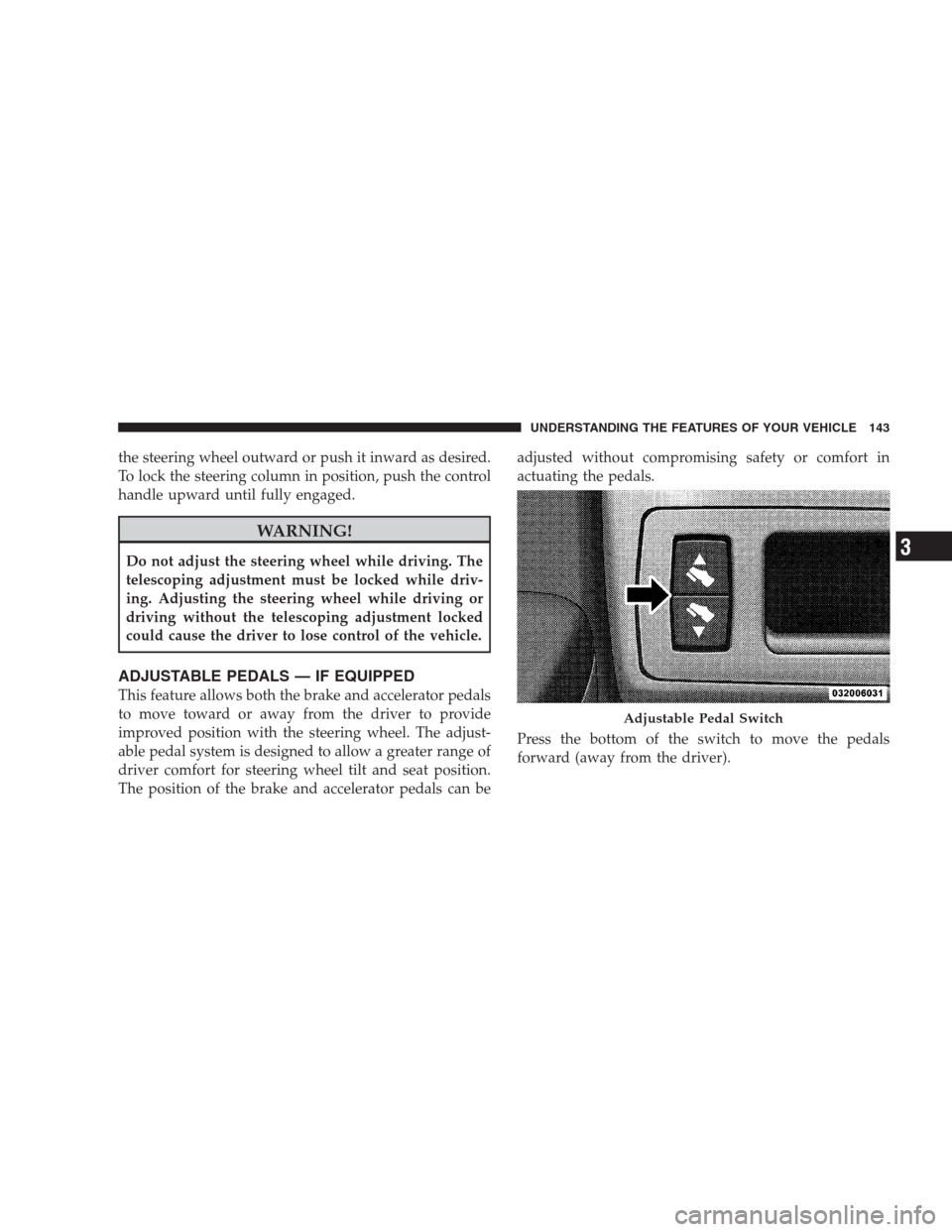
Press the bottom of the switch to move the pedals
forward (away from the driver).
Adjustable Pedal Switch
UNDERSTANDING THE FEATURES OF YOUR VEHICLE 143
3
Page 267 of 521
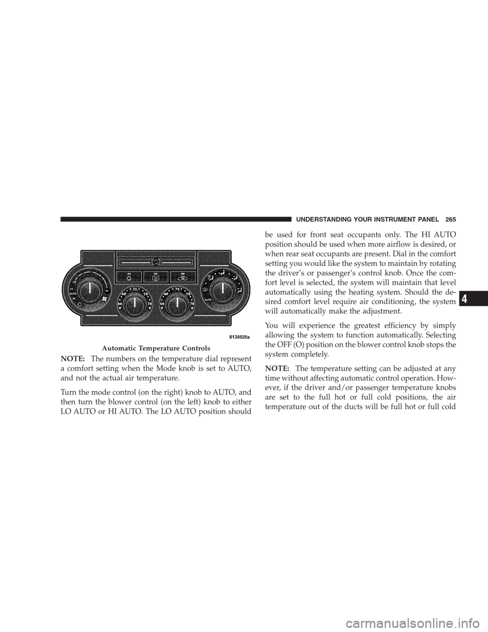
NOTE:The numbers on the temperature dial represent
a comfort setting when the Mode knob is set to AUTO,
and not the actual air temperature.
Turn the mode control (on the right) knob to AUTO, and
then turn the blower control (on the left) knob to either
LO AUTO or HI AUTO. The LO AUTO position shouldbe used for front seat occupants only. The HI AUTO
position should be used when more airflow is desired, or
when rear seat occupants are present. Dial in the comfort
setting you would like the system to maintain by rotating
the driver’s or passenger’s control knob. Once the com-
fort level is selected, the system will maintain that level
automatically using the heating system. Should the de-
sired comfort level require air conditioning, the system
will automatically make the adjustment.
You will experience the greatest efficiency by simply
allowing the system to function automatically. Selecting
the OFF (O) position on the blower control knob stops the
system completely.
NOTE:The temperature setting can be adjusted at any
time without affecting automatic control operation. How-
ever, if the driver and/or passenger temperature knobs
are set to the full hot or full cold positions, the air
temperature out of the ducts will be full hot or full cold
Automatic Temperature Controls
UNDERSTANDING YOUR INSTRUMENT PANEL 265
4