Page 25 of 36

Technical TrainingNP10-V8JLR: AJ133 5.0-Liter DFI V8 Engine04/14/20093-23
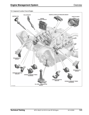
Engine Management SystemHeated Oxygen Sensors
Upstream Universal Heated Exhaust Gas Oxygen Sensors
In order to improve the control of the air : fuel ratio
(AFR) under varying engine conditions, a linear or ‘uni-
versal’ heated exhaust gas oxygen (UHEGO) sensor is
used in the upstream location. The UHEGO has a vary-
ing current response to changes in the exhaust gas oxy-
gen content.
The AFR can be maintained more precisely within a
range from approximately 12:1 to 18:1, not just stoichio-
metric. Voltage is maintained at approximately 450 mV
by applying a current.
The current required to maintain the constant voltage is
directly proportional to the AFR. A higher current indi-
cates a leaner condition; a lower current indicates a
richer condition. The current varies with the temperature
of the sensor and is therefore difficult to measure for
technician diagnostic purposes.
The upstream UHEGO sensors need to operate at high
temperatures – 750°C (1,382°F) – in order to function
correctly. To achieve this, the sensors are fitted with
heater elements that are controlled by a PWM signal
from the ECM.
The heater elements are operated immediately following
engine start and also during low load conditions when
the temperature of the exhaust gases is insufficient to
maintain the required sensor temperatures.A non-functioning heater delays the sensor’s readiness
for closed loop control and influences emissions. The
PWM duty cycle is carefully controlled to reduce ther-
mal shock risk to cold sensors.
The upstream UHEGO sensors are mounted to the
engine on the exhaust manifolds, in the mating flange to
the exhaust pipes. There is one sensor per bank. The sen-
sors are fitted during engine assembly.
Upstream UHEGO Output
NP10V8108
+10 mA
NOMINAL APPLIED CURRENT
-10 mA
AFR 12:1
APPLIED CURRENT(APPROXIMATE)
AFR 18:1λ = 1
Page 26 of 36

3-2404/14/2009NP10-V8JLR: AJ133 5.0-Liter DFI V8 EngineTechnical Training
Heated Oxygen SensorsEngine Management System
Downstream Heated Oxygen Sensors
The latest switching downstream exhaust sensors are
precise-control heated oxygen sensors (HO2S). These
sensors have a tighter lean/rich tolerance compared to
previous HO2S. The only visible distinction between the
current and previous HO2S is the part number.
The downstream HO2S uses smaller elements in its con-
struction to enable quicker heat-up times to control fuel
metering at lower temperatures (emissions).
The primary function of the downstream HO2S is to
ensure correct operation of the three way catalyst.
The downstream HO2S uses Zirconium technology that
produces an output voltage dependant upon the ratio of
exhaust gas oxygen to the ambient oxygen. The device
contains a Galvanic cell surrounded by gas-permeable
ceramic, the voltage of which depends upon the level of
O2 diffusing through.
Nominal output voltage of the device for lambda = 1 is
300 – 500mV. As the fuel mixture becomes richer (<1)
the voltage tends towards 900mV and as it becomes
leaner (lambda > 1) the voltage tends towards 0 volts. The downstream HO2S are mounted in the exhaust sys-
tem part way in the rear of the catalyst.
Downstream HO2S Output
NP10V8115
V
λ = 1
4.5V
Page 27 of 36

Technical TrainingNP10-V8JLR: AJ133 5.0-Liter DFI V8 Engine04/14/20093-25
Engine Management SystemHeated Oxygen Sensors
Safety Precautions
WARNINGS:
• Anti-seize compound used on service sensor threads may be a health hazard. Avoid skin
contact.
• Exhaust system components, catalysts in particular, operate at high temperatures and
remain hot for a long time after operation.
CAUTIONS:
• Oxygen sensors must be treated with the utmost care before and during the fitting
process. The sensors have ceramic material
within them that can easily crack if
dropped or over-torqued. They must be
tightened to the specified torque figure with
a calibrated torque wrench. Care should be
taken not to contaminate the sensor tip
when the anti-seize compound is used on
the thread.
• To prevent damage to the sensors, a special tool (box spanner) should be used when
removing.
• If the sensor sticks in the exhaust, apply de- seize product and use a repeating tighten
and loosen strategy.
• Ensure that the sensor harness is robustly secured away from moving or hot parts. Failure Modes
• Mechanical fitting and integrity of the sensor (i.e.
cracked)
• Sensor open circuit/disconnected
• Short circuit to battery voltage or ground.
• Lambda ratio outside operating band
• Crossed sensors (RH bank fitted to LH bank and vice-versa)
• Contamination from leaded fuel or other sources
• Harness damage
• Air leak into exhaust system (cracked pipe/weld or loose fixings)
Failure Symptoms
• Default to open loop fuel metering
• High CO reading
• Strong smell of sulfur (rotten eggs) until default condition
• Excess emissions
• Unstable operation
• Reduced performance
Page 28 of 36
 senso")
3-2604/14/2009NP10-V8JLR: AJ133 5.0-Liter DFI V8 EngineTechnical Training
Ambient Air Temperature SensorEngine Management System
AMBIENT AIR TEMPERATURE SENSOR
The ambient air temperature (AAT) sensor is located in
the underside of the LH exterior door mirror. The sensor
is an NTC thermistor – the element resistance decreases
as the sensor temperature increases, which produces a
low signal voltage.
The ECM supplies the sensor with a 5V reference volt-
age and ground, and measures the returned signal volt-
age as an outside temperature.
The AAT signal is used by the ECM for a number of
functions including engine cooling fan control and A/C
compressor displacement control.
The ECM also transmits an ambient temperature mes-
sage on the high speed CAN bus for use by other control
modules.
NOTE: If there is a fault with the AAT sensor, the ECM
calculates the AAT from the temperature inputs of the
IAT sensors. If the AAT sensor and the temperature
inputs of the IAT sensors are all faulty, the ECM adopts a
default ambient temperature value of 20°C (68°F).
Failure Mode
• Default value of 20°C (68°F)
PinFunction
Pin 1 5V supply
Pin 2 Ground
Page 29 of 36

Technical TrainingNP10-V8JLR: AJ133 5.0-Liter DFI V8 Engine04/14/20093-27
Engine Management SystemIgnition Coils
IGNITION COILS
The ignition coil operates according to the laws of induc-
tion. The unit consists of two magnetically-coupled cop-
per coils (primary and secondary windings).The coil has
a 3-pin connector and incorporates an internal switching
module.
Energy is stored in the primary winding’s magnetic field
by allowing a current to flow through the primary circuit
switched by the switching module.
At the firing point the current flow is interrupted by the
ECM, which induces secondary voltage in the coil’s sec-
ondary winding.
The secondary circuit has a diode on the ground side in
order to reduce any undesired switch-on voltage, which
could lead to misfiring into the intake manifold to an
uncritical value.
The switching module will limit the primary current to a
maximum value. It also limits the maximum primary
voltage by voltage clamping. This protects the switching
module and (along with other parameters) determines
the maximum possible secondary voltage. Safety Precautions
WARNING:
• Ignition coils generate high voltages that can cause personal injury. Appropriate
safety instructions on handling high volt-
ages must be observed.
CAUTIONS:
• The spark plugs fitted are critical to the performance of the ignition and misfire
detection systems. No attempt should be
made to ‘clean’ or ‘gap’ these spark plugs.
They are very reliable and unlikely to cause
problems. If a faulty spark plug is sus-
pected, try substituting it before condemn-
ing it. It is essential that only factory-
approved spark plugs be used in service.
DO NOT attempt to use ‘equivalent’ spark
plugs, even if they are of a similar design.
Use of unapproved spark plugs will cause
the misfire detection system to malfunction
and erroneously store misfire faults.
• To avoid damage to the insulator, always use the correct specified spark plugs and correct
plug removal/refit plug socket.
NOTE: A single capacitor is used in the engine harness to
suppress interference from the ignition coil power supply.
Radio Frequency Interference Suppressor
The radio frequency interference (RFI) suppressor is
mounted on the harness carrier bracket on at the upper
rear of the engine.
NP10V8109
NP10V8110
Page 30 of 36

3-2804/14/2009NP10-V8JLR: AJ133 5.0-Liter DFI V8 EngineTechnical Training
Fuel Tank Canister Purge ValveEngine Management System
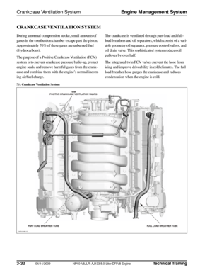
FUEL TANK CANISTER PURGE VALVE
To comply with legislation in fuel evaporative loss, the evaporative emissions loss control system is used on all vehicles.
Its purpose is to minimize the evaporative loss of fuel vapor from the fuel system to the atmosphere. This is achieved by
venting the fuel system through a vapor trap – a canister filled with vapor-absorbing charcoal. The charcoal acts like a
sponge and stores the vapor until the canister is purged under the control of the ECM into the engine for combustion. The
carry-over system uses the DMTL system to check for fuel tank integrity.
The canister is connected with the intake manifold, after the throttle body, via a purge valve. This valve is opened and
closed according to a PWM signal from the ECM. The system does not work properly in the case of leakage or clog-
ging within the system or if the purge valve cannot be controlled.
The canister is purged by drawing clean air through the
charcoal, which carries the hydrocarbons into the engine
where they are combusted. To maintain driveability and
emission control, purging must be closely controlled as a
1% concentration of fuel vapor from the canister in the
air intake may shift the air/fuel ratio by as much as 20%.
Purging must be carried out at regular intervals to regen-
erate the charcoal, since the storage capacity is limited.
The purge function is alternated with the fuel metering
adaptation, as both cannot be active at the same time.
The ECM alters the PWM signal to the purge valve to con-
trol the rate of purging of the canister. The purging of the
canister is done in a controlled manner in order to maintain
the correct stoichiometric air/fuel mixture for the engine.
The ECM also ensures that the canister itself is purged
frequently enough to prevent fuel saturation of the char-
coal, which could lead to an excessive buildup of fuel
vapor (and vapor pressure) in the system, increasing the
likelihood of vapor leaks. Failure Modes
• Valve drive open circuit
• Short circuit to battery voltage or ground
• Valve/pipe work blocked
• Valve stuck open
• Pipe work leaking/disconnected
• Noisy valve
Failure Symptoms
• Engine may possibly stall on return to idle (if valve
stuck open)
• Poor idling quality (if valve stuck open)
• Fuel metering adaptations forced excessively rich if canister is clear with valve stuck open
• Fuel metering adaptations forced excessively lean if canister is saturated with valve stuck open
• Saturation of canister (if valve stuck closed)
PURGE VALVE
AIR FLOWS ENS OR
THROTTLE
FUEL TANK CARBON FILTER
INTAKE
MANIFOLD
NP10V8111
Page 31 of 36
Technical TrainingNP10-V8JLR: AJ133 5.0-Liter DFI V8 Engine04/14/20093-29
Engine Management SystemViscous Fan Control
VISCOUS FAN CONTROL (LAND ROVER ONLY)
On Land Rover vehicles, the ECM uses an electroni-
cally-controlled viscous-coupled fan to provide engine
cooling. The ECM supplies the fan with a PWM signal
that controls the amount of slippage of the fan, thus pro-
viding the correct amount of cooling fan speed and air-
flow. The EMS uses a Hall-effect sensor to determine the
fan speed.
Failure Modes
• Solenoid drive open circuit
• Short circuit to battery voltage or ground
• Fan speed monitor open circuit
• Physically damaged fan or viscous coupling
Page 32 of 36
 is a high-speed")
3-3004/14/2009NP10-V8JLR: AJ133 5.0-Liter DFI V8 EngineTechnical Training
Controller Area Network Engine Management System
CONTROLLER AREA NETWORK
The Controller Area Network (CAN) is a high-speed
serial interface for sharing dynamic signals between elec-
tronic control modules. CAN communications are ‘self-
checked’ for errors, and if an error is detected the message
is ignored by the receiving electronic control module.
Due to the high rate of information exchange, the system
has a high degree of latency. This allows for a high num-
ber of errors to be present without reducing the data
transfer rate. In practice, this is a very reliable system.
Each CAN message is transmitted by one electronic con-
trol module and received by all other electronic control
modules on the CAN bus. Each message contains a fixed
structure of signals. The data exchanged is used so that
each electronic control module does not need to have a
hardwired sensor for each input. The CAN message iden-
tifiers are arranged by a network tool, which can guarantee
that all messages meet their specified timing needs.
Signal Overview
The CAN communication system is a differential bus
using a twisted pair that is normally very reliable. If either
or both of the wires of the twisted pair CAN bus is open-
or short-circuited, a CAN time-out fault will occur.
Below is a list of additional electronic control modules that
the ECM will communicate with on the CAN network:
• Instrument cluster
• Steering angle sensor
•TCM
• Active rear locking differential, if equipped
• Adaptive cruise control
• Electronic parking brake
Failure Modes
• CAN bus wiring short circuit or open circuit
• Incompatible software and message versions


On Land Rover vehicles, the ECM uses an elec")