Page 1 of 36
Technical Training
Technical Introduction
NP10
-
V8JLR: AJ133 5.0
-
Liter DFI V8 Engine
Engine Management System
NP10-V8JLR 04/2009Printed in USA
NP10V8COV
Page 2 of 36
This publication is intended for instructional purposes only. Always refer to the appropriate service publication for
specific details and procedures.
All rights reserved. All material contained herein is based on the latest information available at the time of publication.
The right is reserved to make changes at any time without notice.
© 2009 Jaguar Land Rover North America LLC
Page 3 of 36

Technical Training
NP10-V8JLR: AJ133 5.0-Liter DFI V8 Engine 04/14/2009
3-1
Engine Management System
Table of Contents
Overview . . . . . . . . . . . . . . . . . . . . . . . . . . . . . . . . . 2
Engine Control Module . . . . . . . . . . . . . . . . . . . . . . 8
Relays . . . . . . . . . . . . . . . . . . . . . . . . . . . . . . . . . . . 10
Crankshaft Position Sensor . . . . . . . . . . . . . . . . . . 11
Camshaft Position Sensor . . . . . . . . . . . . . . . . . . . 13
Engine Coolant Temperature Sensor . . . . . . . . . . 14
Knock Sensors . . . . . . . . . . . . . . . . . . . . . . . . . . . . 15
Manifold Absolute Pressure Sensor . . . . . . . . . . . 16
Mass Air Flow Sensor . . . . . . . . . . . . . . . . . . . . . . 17
Temp. / Manifold Absolute Pressure Sensor . . . . 18
Throttle Position Sensor . . . . . . . . . . . . . . . . . . . . 19
Accelerator Pedal Position Sensor . . . . . . . . . . . . 21
Heated Oxygen Sensors . . . . . . . . . . . . . . . . . . . . 22
Ambient Air Temperature Sensor. . . . . . . . . . . . . 26
Ignition Coils . . . . . . . . . . . . . . . . . . . . . . . . . . . . . 27
Fuel Tank Canister Purge Valve . . . . . . . . . . . . . . 28
Viscous Fan Control (Land Rover only) . . . . . . . 29
Controller Area Network. . . . . . . . . . . . . . . . . . . . 30
On-Board Diagnostic Monitoring . . . . . . . . . . . . . 31
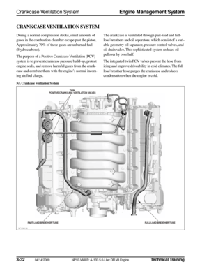
Crankcase Ventilation System . . . . . . . . . . . . . . . 32
Page 4 of 36
 and super-
charged (SC) engine")
3-2
04/14/2009 NP10-V8JLR: AJ133 5.0-Liter DFI V8 Engine
Technical Training
Overview
Engine Management System
OVERVIEW
The 5.0-Liter V8 normally aspirated (NA) and super-
charged (SC) engines are managed by the engine control
module (ECM), which controls the following:
• Engine fuel metering
• Ignition timing
• Camshaft timing
• Camshaft Profile Switching (CPS)
• Closed loop fuel metering
• Knock control
• Idle speed control
• Emission control
• On-Board Diagnostics (OBD)
• Interface with the immobilization system
• Speed control
The ECM controls the engine fuel metering by provid-
ing sequential fuel injection to all cylinders. Ignition is
controlled by a direct ignition system, provided by eight
coil-on-plug (COP) units. The ECM is able to detect and
correct for ignition knock on each cylinder and adjust the
ignition timing for each cylinder to achieve optimum
performance.
The ECM uses a torque-based strategy to generate the
torque required by driver demand and the other vehicle
control modules, using input from various sensors to cal-
culate the required torque. The ECM also interfaces with
other vehicle electronic control modules to obtain addi-
tional information (road speed from the ABS control
module, for example). The ECM processes these signals
and determines how much torque to generate, using vari-
ous actuators to supply air, fuel, and spark to the engine
(electronic throttle, injectors, coils, etc.).
Page 5 of 36
Technical Training
NP10-V8JLR: AJ133 5.0-Liter DFI V8 Engine 04/14/2009
3-3
Engine Management System
Overview
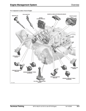
NA Component Location: Front of Engine
NP10V8089
THROTTLE BODY
MANIFOLD ABS
OLUTE PRESSURE S ENSOR
ENGINE
CONTROL MODULE
FUEL INJECTOR
IGNITION COIL
MASS AIR FLOW SENS OR
CAMS HAFT POS ITION
S ENS ORS
VARIABLE CAMS HAFT TIMING
S OLENOIDS
OIL LEVEL / TEMPERATURESENS OR CAMS
HAFT POS ITION
S ENS ORS
VARIABLE CAMSHAFT TIMING
S OLENOIDS MASS AIR FLOW
SENS OR
Page 6 of 36
3-4
04/14/2009 NP10-V8JLR: AJ133 5.0-Liter DFI V8 Engine
Technical Training
Overview
Engine Management System
NA Component Location: Rear of Engine
NP10V8090
FUEL RAIL
PRESSURE S ENSOR
CAMS HAFT
PROFILE S WITCHING
S OLENOID
ENGINE
COOLANT TEMP. SENS OR
UPS TREAM
UHEGO
DOWNS TREAM
HO2S (2)
CRANKS
HAFT
POS ITION S ENSOR
UPS
TREAM
UHEGO
CAMS
HAFT
PROFILE S WITCHING
S OLENOID
KNOCK
S ENS ORS (4) INTAKE RUNNER
CONTROL
Page 7 of 36
Technical Training
NP10-V8JLR: AJ133 5.0-Liter DFI V8 Engine 04/14/2009
3-5
Engine Management System
Overview
SC Component Location: Front of Engine
NP10V8091
THROTTLE BODY
MANIFOLD ABS
OLUTE PRESSURE S ENSOR
ENGINE
ENGINECONTROL MODULECONTROL MODULEENGINE
CONTROL MODULE
FUEL INJECTOR
IGNITION COIL
MASS AIR FLOW SENS OR
CAMS HAFT POS ITION
S ENS ORS
VARIABLE CAMS HAFT TIMING
S OLENOIDS
OIL LEVEL / TEMPERATURESENS OR CAMS
HAFT POS ITION
S ENS ORS
VARIABLE CAMSHAFT TIMING
S OLENOIDS MASS AIR FLOW
SENS OR
Page 8 of 36
3-6
04/14/2009 NP10-V8JLR: AJ133 5.0-Liter DFI V8 Engine
Technical Training
Overview
Engine Management System
SC Component Location: Rear of Engine
NP10V8092
FUEL RAIL
PRESSURE S ENSOR
ENGINE
COOLANT TEMP. SENS OR
UPSTREAM
UHEGO
DOWNS TREAM
HO2S (2)
CRANKS
HAFT
POS ITION S ENSOR
UPS
TREAM
UHEGO
ENGINE
CONTROL MODULE KNOCK
S ENS ORS (4) TEMPERATURE AND
MANIFOLD ABS OLUTE PRESSURE S ENSOR