2009 INFINITI QX56 ignition
[x] Cancel search: ignitionPage 1852 of 4171
INTAKE MANIFOLDEM-29
< ON-VEHICLE REPAIR >
C
DE
F
G H
I
J
K L
M A
EM
NP
O
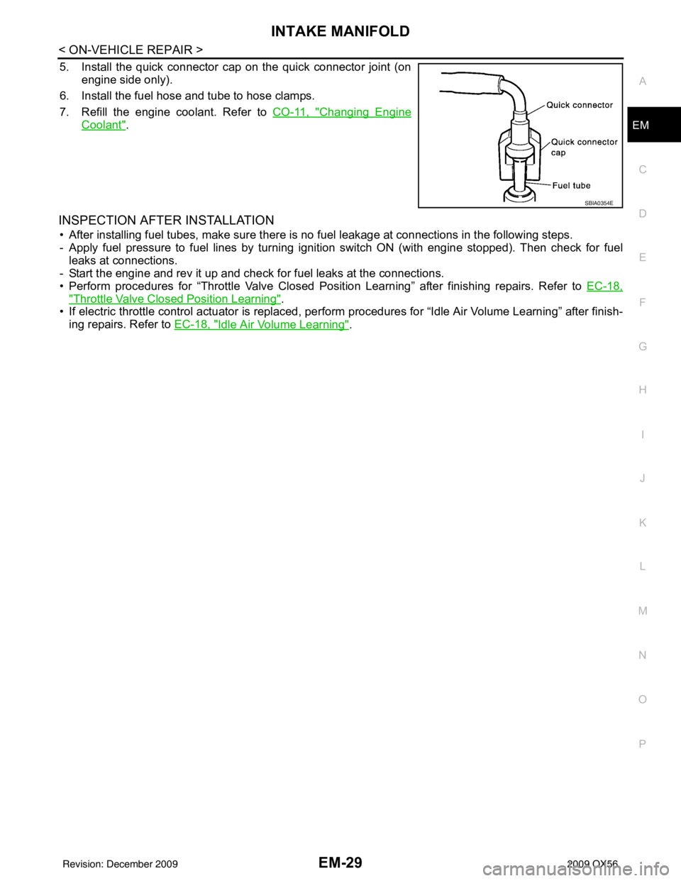
5. Install the quick connector cap on the quick connector joint (on
engine side only).
6. Install the fuel hose and tube to hose clamps.
7. Refill the engine coolant. Refer to CO-11, "
Changing Engine
Coolant".
INSPECTION AFTER INSTALLATION
• After installing fuel tubes, make sure there is no fuel leakage at connections in the following steps.
- Apply fuel pressure to fuel lines by turning ignition switch ON (with engine stopped). Then check for fuel leaks at connections.
- Start the engine and rev it up and check for fuel leaks at the connections.
• Perform procedures for “Throttle Valve Closed Position Learning” after finishing repairs. Refer to EC-18,
"Throttle Valve Closed Position Learning".
• If electric throttle control actuator is replaced, per form procedures for “Idle Air Volume Learning” after finish-
ing repairs. Refer to EC-18, "
Idle Air Volume Learning".
SBIA0354E
Revision: December 20092009 QX56
Page 1860 of 4171
IGNITION COILEM-37
< ON-VEHICLE REPAIR >
C
DE
F
G H
I
J
K L
M A
EM
NP
O
IGNITION COIL
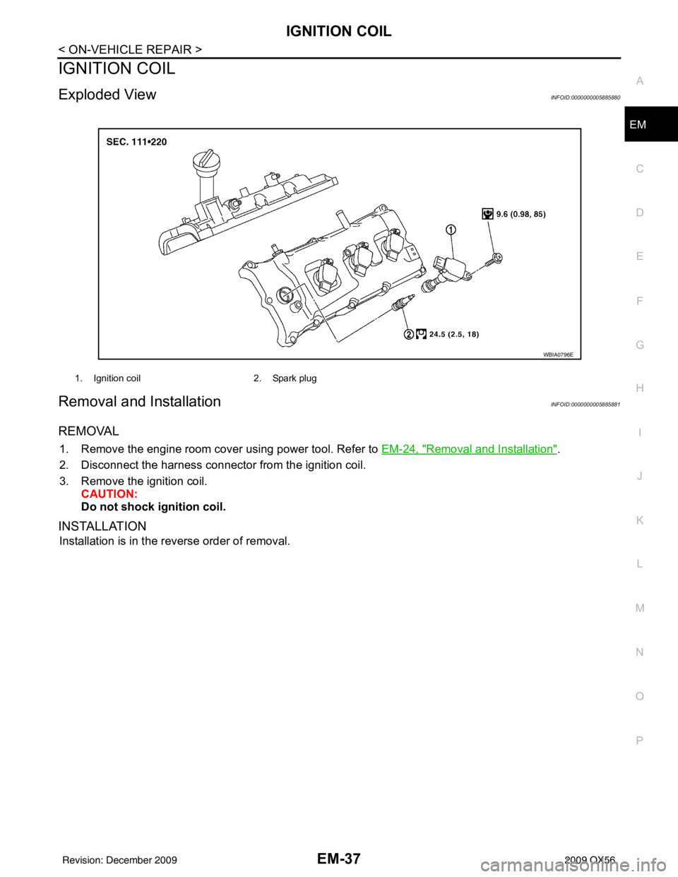
Exploded ViewINFOID:0000000005885880
Removal and InstallationINFOID:0000000005885881
REMOVAL
1. Remove the engine room cover using power tool. Refer to
EM-24, "Removal and Installation".
2. Disconnect the harness connector from the ignition coil.
3. Remove the ignition coil. CAUTION:
Do not shock ignition coil.
INSTALLATION
Installation is in the reverse order of removal.
1. Ignition coil 2. Spark plug
WBIA0796E
Revision: December 20092009 QX56
Page 1861 of 4171
EM-38
< ON-VEHICLE REPAIR >
ROCKER COVER
ROCKER COVER
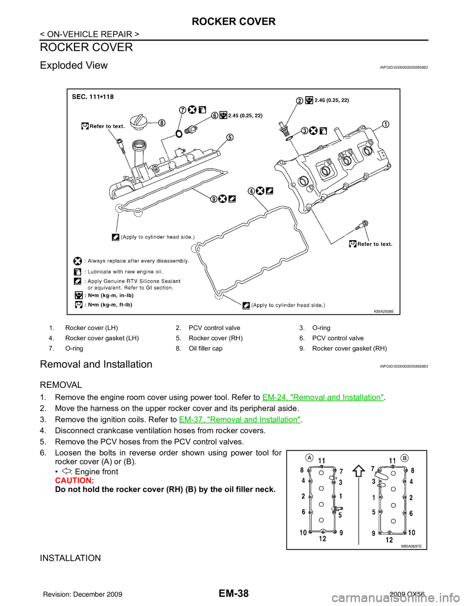
Exploded ViewINFOID:0000000005885882
Removal and InstallationINFOID:0000000005885883
REMOVAL
1. Remove the engine room cover using power tool. Refer to EM-24, "Removal and Installation".
2. Move the harness on the upper rocker cover and its peripheral aside.
3. Remove the ignition coils. Refer to EM-37, "
Removal and Installation".
4. Disconnect crankcase ventilation hoses from rocker covers.
5. Remove the PCV hoses from the PCV control valves.
6. Loosen the bolts in reverse order shown using power tool for rocker cover (A) or (B).
• : Engine front
CAUTION:
Do not hold the rocker cover ( RH) (B) by the oil filler neck.
INSTALLATION
1. Rocker cover (LH) 2. PCV control valve3. O-ring
4. Rocker cover gasket (LH) 5. Rocker cover (RH)6. PCV control valve
7. O-ring 8. Oil filler cap9. Rocker cover gasket (RH)
KBIA2508E
WBIA0697E
Revision: December 20092009 QX56
Page 1865 of 4171
EM-42
< ON-VEHICLE REPAIR >
FUEL INJECTOR AND FUEL TUBE
• Lubricate O-ring with new engine oil.
• Do not clean O-ring with solvent.
• Make sure that O-ring and its mating part are free of foreign material.
• When installing O-ring, be careful not to scratch it with tool or fingernails. Also be careful not to
twist or stretch O-ring. If O-ring was stretc hed while it was being attached, do not insert it
quickly into fuel tube.
• Insert O-ring straight into fuel tube. Do not angle or twist it.
3. Install fuel injector to fuel tube.
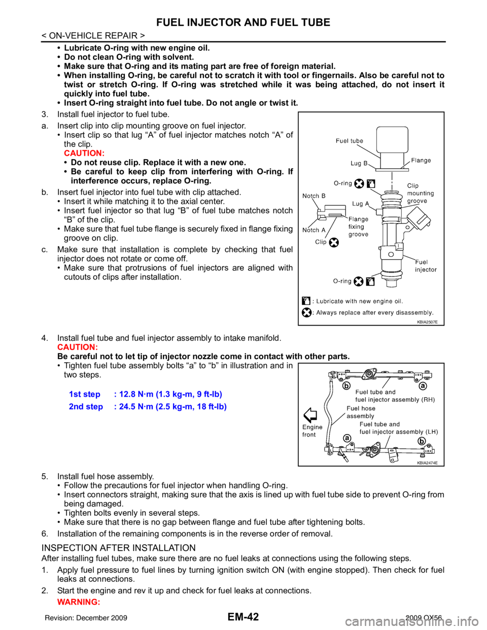
a. Insert clip into clip mounting groove on fuel injector. • Insert clip so that lug “A” of fuel injector matches notch “A” ofthe clip.
CAUTION:
• Do not reuse clip. Replace it with a new one.
• Be careful to keep clip from interfering with O-ring. Ifinterference occurs, replace O-ring.
b. Insert fuel injector into fuel tube with clip attached. • Insert it while matching it to the axial center.
• Insert fuel injector so that lug “B” of fuel tube matches notch
“B” of the clip.
• Make sure that fuel tube flange is securely fixed in flange fixing groove on clip.
c. Make sure that installation is complete by checking that fuel injector does not rotate or come off.
• Make sure that protrusions of fuel injectors are aligned withcutouts of clips after installation.
4. Install fuel tube and fuel injector assembly to intake manifold. CAUTION:
Be careful not to let tip of injector nozzle come in contact with other parts.
• Tighten fuel tube assembly bolts “a” to “b” in illustration and in
two steps.
5. Install fuel hose assembly. • Follow the precautions for fuel injector when handling O-ring.
• Insert connectors straight, making sure that the axis is lined up with fuel tube side to prevent O-ring from
being damaged.
• Tighten bolts evenly in several steps.
• Make sure that there is no gap between flange and fuel tube after tightening bolts.
6. Installation of the remaining components is in the reverse order of removal.
INSPECTION AFTER INSTALLATION
After installing fuel tubes, make sure there are no fuel leaks at connections using the following steps.
1. Apply fuel pressure to fuel lines by turning ignition switch ON (with engine stopped). Then check for fuel leaks at connections.
2. Start the engine and rev it up and check for fuel leaks at connections. WARNING:
KBIA2507E
1st step : 12.8 N·m (1.3 kg-m, 9 ft-lb)
2nd step : 24.5 N·m (2.5 kg-m, 18 ft-lb)
KBIA2474E
Revision: December 20092009 QX56
Page 1875 of 4171
EM-52
< ON-VEHICLE REPAIR >
TIMING CHAIN
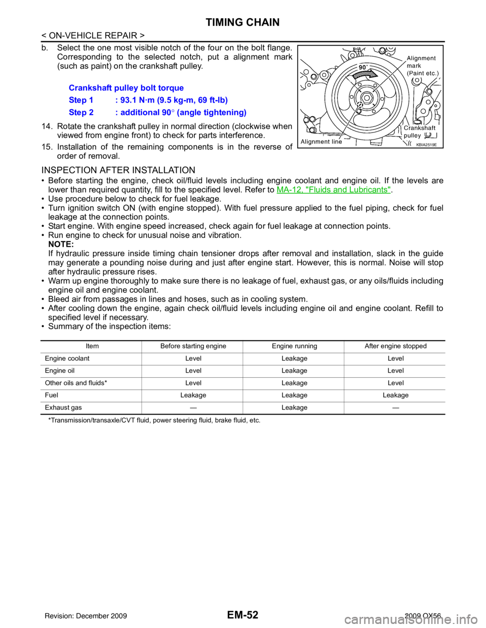
b. Select the one most visible notch of the four on the bolt flange.Corresponding to the selected notch, put a alignment mark
(such as paint) on the crankshaft pulley.
14. Rotate the crankshaft pulley in normal direction (clockwise when viewed from engine front) to check for parts interference.
15. Installation of the remaining components is in the reverse of order of removal.
INSPECTION AFTER INSTALLATION
• Before starting the engine, check oil/fluid levels in cluding engine coolant and engine oil. If the levels are
lower than required quantity, fill to the specified level. Refer to MA-12, "
Fluids and Lubricants".
• Use procedure below to check for fuel leakage.
• Turn ignition switch ON (with engine stopped). With fuel pressure applied to the fuel piping, check for fuel leakage at the connection points.
• Start engine. With engine speed increased, che ck again for fuel leakage at connection points.
• Run engine to check for unusual noise and vibration. NOTE:
If hydraulic pressure inside timing chain tensioner drops after removal and installation, slack in the guide
may generate a pounding noise during and just after engine start. However, this is normal. Noise will stop
after hydraulic pressure rises.
• Warm up engine thoroughly to make sure there is no leakage of fuel, exhaust gas, or any oils/fluids including engine oil and engine coolant.
• Bleed air from passages in lines and hoses, such as in cooling system.
• After cooling down the engine, again check oil/fluid levels including engine oil and engine coolant. Refill to
specified level if necessary.
• Summary of the inspection items:
*Transmission/transaxle/CVT fluid, power steering fluid, brake fluid, etc.
Crankshaft pulley bolt torque
Step 1 : 93.1 N·m (9.5 kg-m, 69 ft-lb)
Step 2 : additional 90 ° (angle tightening)
KBIA2519E
Item Before starting engine Engine runningAfter engine stopped
Engine coolant LevelLeakage Level
Engine oil LevelLeakage Level
Other oils and fluids* LevelLeakage Level
Fuel LeakageLeakageLeakage
Exhaust gas —Leakage —
Revision: December 20092009 QX56
Page 1886 of 4171
CAMSHAFTEM-63
< ON-VEHICLE REPAIR >
C
DE
F
G H
I
J
K L
M A
EM
NP
O
• Perform this inspection only when
DTC P0011 is detected in self-diagnostic results of CONSULT III
and it is directed according to inspecti on procedure of EC section. Refer to EC-87, "
On Board Diag-
nosis Logic".
1. Check engine oil level. Refer to LU-8, "
Inspection".
2. Perform the following procedure so as to prevent the engine from being unintentionally started while checking.
a. Release fuel pressure. Refer to EC-487, "
Fuel Pressure Check".
b. Disconnect ignition coil and injector harness connectors if practical.
3. Remove IVT control solenoid valve.
4. Crank engine, and then make sure that engine oil comes out from IVT control cover oil hole. End cranking after checking.
WARNING:
Be careful not to touch rotating parts (drive be lts, idler pulley, and crankshaft pulley, etc.).
CAUTION:
• Engine oil may squirt from IVT control solenoid valve installation hole during cranking. Use a
shop cloth to prevent engine oil from splash ing on worker, engine components and vehicle.
• Do not allow engine oil to get on rubber components such as drive belts or engine mount insula- tors. Immediately wipe off any splashed engine oil.
5. Clean oil groove between oil strainer and IVT control solenoid valve if engine oil does not come out from IVT control valve cover oil hole. Refer to LU-7, "
Schematic".
6. Remove components between IVT control solenoid valve and camshaft sprocket (INT), and then check each oil groove for clogging.
• Clean oil groove if necessary.
7. After inspection, installation of the remaining components is in the reverse order of removal.
Revision: December 20092009 QX56
Page 1892 of 4171
CYLINDER HEADEM-69
< ON-VEHICLE REPAIR >
C
DE
F
G H
I
J
K L
M A
EM
NP
O
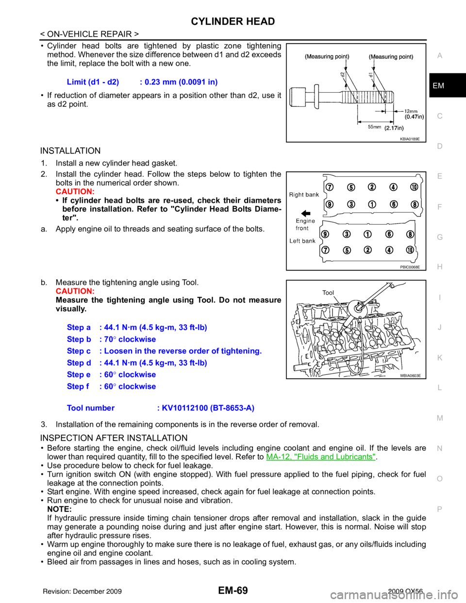
• Cylinder head bolts are tightened by plastic zone tightening
method. Whenever the size difference between d1 and d2 exceeds
the limit, replace the bolt with a new one.
• If reduction of diameter appears in a position other than d2, use it as d2 point.
INSTALLATION
1. Install a new cylinder head gasket.
2. Install the cylinder head. Follow the steps below to tighten the bolts in the numerical order shown.
CAUTION:
• If cylinder head bolts are re-used, check their diameters
before installation. Refer to "Cylinder Head Bolts Diame-
ter".
a. Apply engine oil to threads and seating surface of the bolts.
b. Measure the tightening angle using Tool. CAUTION:
Measure the tightening angl e using Tool. Do not measure
visually.
3. Installation of the remaining components is in the reverse order of removal.
INSPECTION AFTER INSTALLATION
• Before starting the engine, check oil/fluid levels including engine coolant and engine oil. If the levels are lower than required quantity, fill to the specified level. Refer to MA-12, "
Fluids and Lubricants".
• Use procedure below to check for fuel leakage.
• Turn ignition switch ON (with engine stopped). With fuel pressure applied to the fuel piping, check for fuel
leakage at the connection points.
• Start engine. With engine speed increased, check again for fuel leakage at connection points.
• Run engine to check for unusual noise and vibration.
NOTE:
If hydraulic pressure inside timing chain tensioner drops after removal and installation, slack in the guide
may generate a pounding noise during and just after engine start. However, this is normal. Noise will stop
after hydraulic pressure rises.
• Warm up engine thoroughly to make sure there is no leakage of fuel, exhaust gas, or any oils/fluids including
engine oil and engine coolant.
• Bleed air from passages in lines and hoses, such as in cooling system. Limit (d1 - d2) : 0.23 mm (0.0091 in)
KBIA0189E
PBIC0068E
Step a : 44.1 N·m (4.5 kg-m, 33 ft-lb)
Step b : 70°
clockwise
Step c : Loosen in the reverse order of tightening.
Step d : 44.1 N·m (4.5 kg-m, 33 ft-lb)
Step e : 60 ° clockwise
Step f : 60° clockwise
Tool number : KV10112100 (BT-8653-A)
WBIA0603E
Revision: December 20092009 QX56
Page 1903 of 4171
EM-80
< REMOVAL AND INSTALLATION >
ENGINE ASSEMBLY
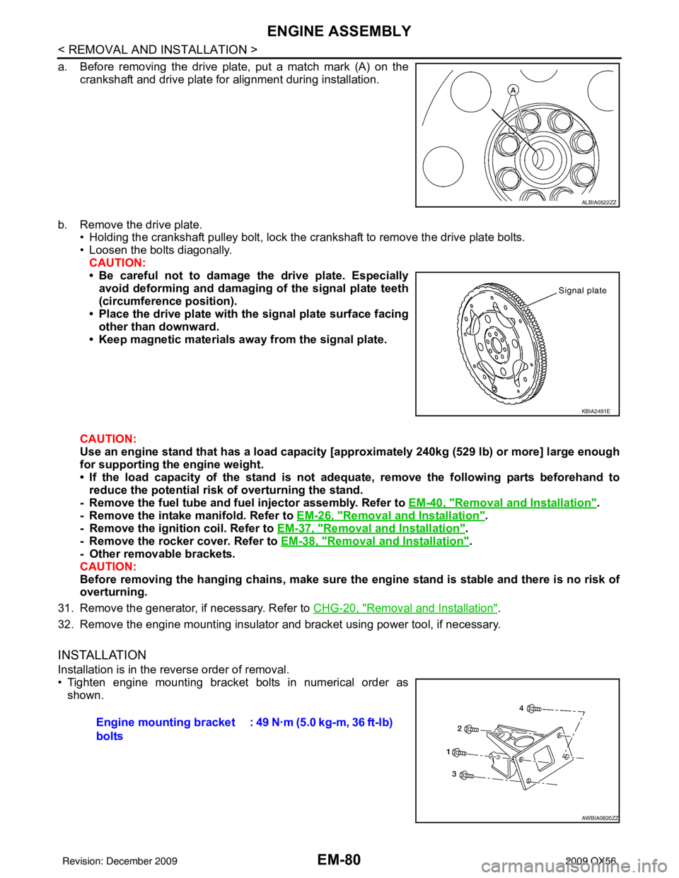
a. Before removing the drive plate, put a match mark (A) on thecrankshaft and drive plate for alignment during installation.
b. Remove the drive plate. • Holding the crankshaft pulley bolt, lock the crankshaft to remove the drive plate bolts.
• Loosen the bolts diagonally.
CAUTION:
• Be careful not to damage the drive plate. Especiallyavoid deforming and damaging of the signal plate teeth
(circumference position).
• Place the drive plate with th e signal plate surface facing
other than downward.
• Keep magnetic materials away from the signal plate.
CAUTION:
Use an engine stand that has a load capacity [a pproximately 240kg (529 lb) or more] large enough
for supporting the engine weight.
• If the load capacity of the stand is not adeq uate, remove the following parts beforehand to
reduce the potential risk of overturning the stand.
- Remove the fuel tube and fuel injector assembly. Refer to EM-40, "
Removal and Installation".
- Remove the intake manifold. Refer to EM-26, "
Removal and Installation".
- Remove the ignition coil. Refer to EM-37, "
Removal and Installation".
- Remove the rocker cover. Refer to EM-38, "
Removal and Installation".
- Other removable brackets.
CAUTION:
Before removing the hanging chains, make sure th e engine stand is stable and there is no risk of
overturning.
31. Remove the generator, if necessary. Refer to CHG-20, "
Removal and Installation".
32. Remove the engine mounting insulator and bracket using power tool, if necessary.
INSTALLATION
Installation is in the reverse order of removal.
• Tighten engine mounting bracket bolts in numerical order as shown.
ALBIA0522ZZ
KBIA2491E
Engine mounting bracket
bolts : 49 N·m (5.0 kg-m, 36 ft-lb)
AWBIA0820ZZ
Revision: December 20092009 QX56