2009 INFINITI QX56 ignition
[x] Cancel search: ignitionPage 1904 of 4171
ENGINE ASSEMBLYEM-81
< REMOVAL AND INSTALLATION >
C
DE
F
G H
I
J
K L
M A
EM
NP
O
CAUTION:
• When replacing an engine or tr
ansmission you must make sure the dowels are installed correctly
during re-assembly.
• Improper alignment caused by missing dowels m ay cause vibration, oil leaks or breakage of driv-
etrain components.
INSPECTION AFTER INSTALLATION
• Before starting the engine, check oil/fluid levels including engine coolant and engine oil. If the levels are lower than required quantity, fill to the specified level. Refer to MA-12, "
Fluids and Lubricants".
• Use procedure below to check for fuel leakage.
• Turn ignition switch ON (with engine stopped). With fuel pressure applied to the fuel piping, check for fuel leakage at the connection points.
• Start engine. With engine speed increased, check again for fuel leakage at connection points.
• Run engine to check for unusual noise and vibration.
NOTE:
If hydraulic pressure inside timing chain tensioner drops after removal and installation, slack in the guide
may generate a pounding noise during and just after engine start. However, this is normal. Noise will stop
after hydraulic pressure rises.
• Warm up engine thoroughly to make sure there is no leakage of fuel, exhaust gas, or any oils/fluids including
engine oil and engine coolant.
• Bleed air from passages in lines and hoses, such as in cooling system.
• After cooling down the engine, again check oil/fluid levels including engine oil and engine coolant. Refill to specified level if necessary.
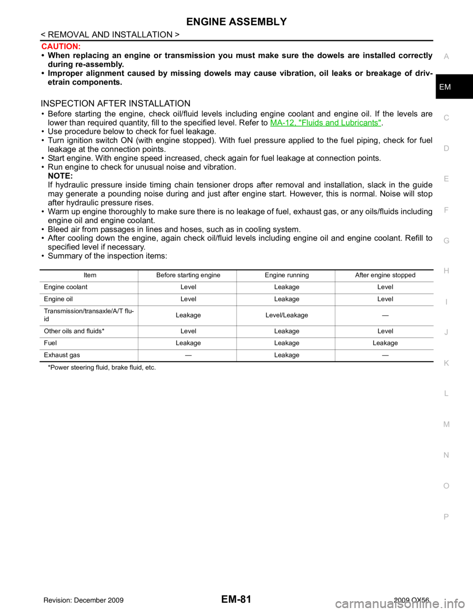
• Summary of the inspection items:
*Power steering fluid, brake fluid, etc. Item
Before starting engine Engine runningAfter engine stopped
Engine coolant LevelLeakage Level
Engine oil LevelLeakage Level
Transmission/transaxle/A/T flu-
id Leakage
Level/Leakage —
Other oils and fluids* LevelLeakage Level
Fuel LeakageLeakage Leakage
Exhaust gas —Leakage —
Revision: December 20092009 QX56
Page 1943 of 4171
EX-2
< PRECAUTION >
PRECAUTIONS
PRECAUTION
PRECAUTIONS
Precaution for Supplemental Restraint System (SRS) "AIR BAG" and "SEAT BELT
PRE-TENSIONER"
INFOID:0000000005851832
The Supplemental Restraint System such as “A IR BAG” and “SEAT BELT PRE-TENSIONER”, used along
with a front seat belt, helps to reduce the risk or severity of injury to the driver and front passenger for certain
types of collision. This system includes seat belt switch inputs and dual stage front air bag modules. The SRS
system uses the seat belt switches to determine the front air bag deployment, and may only deploy one front
air bag, depending on the severity of a collision and w hether the front occupants are belted or unbelted.
Information necessary to service the system safely is included in the SR and SB section of this Service Man-
ual.
WARNING:
• To avoid rendering the SRS inopera tive, which could increase the risk of personal injury or death in
the event of a collision which would result in air bag inflation, all maintenance must be performed by
an authorized NISSAN/INFINITI dealer.
• Improper maintenance, including in correct removal and installation of the SRS, can lead to personal
injury caused by unintent ional activation of the system. For re moval of Spiral Cable and Air Bag
Module, see the SR section.
• Do not use electrical test equipmen t on any circuit related to the SRS unless instructed to in this
Service Manual. SRS wiring harn esses can be identified by yellow and/or orange harnesses or har-
ness connectors.
PRECAUTIONS WHEN USING POWER TOOLS (AIR OR ELECTRIC) AND HAMMERS
WARNING:
• When working near the Airbag Diagnosis Sensor Unit or other Airbag System sensors with the Igni-
tion ON or engine running, DO NOT use air or electri c power tools or strike near the sensor(s) with a
hammer. Heavy vibration could activate the sensor( s) and deploy the air bag(s), possibly causing
serious injury.
• When using air or electric power tools or hammers , always switch the Ignition OFF, disconnect the
battery, and wait at least 3 minu tes before performing any service.
Precaution Necessary for Steering W heel Rotation After Battery Disconnect
INFOID:0000000005851833
NOTE:
• This Procedure is applied only to models with Intelligent Key system and NATS (NISSAN ANTI-THEFT SYS-
TEM).
• Remove and install all control units after disconnecting both battery cables with the ignition knob in the
″LOCK ″ position.
• Always use CONSULT-III to perform self-diagnosis as a part of each function inspection after finishing work.
If DTC is detected, perform trouble diagnosis according to self-diagnostic results.
For models equipped with the Intelligent Key system and NATS, an electrically controlled steering lock mech-
anism is adopted on the key cylinder.
For this reason, if the battery is disconnected or if the battery is discharged, the steering wheel will lock and
steering wheel rotation will become impossible.
If steering wheel rotation is required when battery pow er is interrupted, follow the procedure below before
starting the repair operation.
OPERATION PROCEDURE
1. Connect both battery cables. NOTE:
Supply power using jumper cables if battery is discharged.
2. Use the Intelligent Key or mechanical key to turn the ignition switch to the ″ACC ″ position. At this time, the
steering lock will be released.
3. Disconnect both battery cables. The steering lock will remain released and the steering wheel can be rotated.
4. Perform the necessary repair operation.
Revision: December 20092009 QX56
Page 1944 of 4171

PRECAUTIONSEX-3
< PRECAUTION >
C
DE
F
G H
I
J
K L
M A
EX
NP
O
5. When the repair work is completed, return the ignition switch to the
″LOCK ″ position before connecting
the battery cables. (At this time, the steering lock mechanism will engage.)
6. Perform a self-diagnosis check of al l control units using CONSULT-III.
Revision: December 20092009 QX56
Page 1959 of 4171
AUTO LIGHT SYSTEMEXL-11
< FUNCTION DIAGNOSIS >
C
DE
F
G H
I
J
K
M A
B
EXL
N
O P
AUTO LIGHT SYSTEM
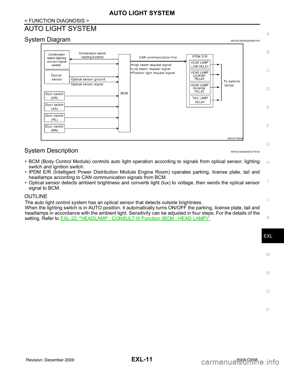
System DiagramINFOID:0000000005867516
System DescriptionINFOID:0000000003776153
• BCM (Body Control Module) controls auto light operati on according to signals from optical sensor, lighting
switch and ignition switch.
• IPDM E/R (Intelligent Power Distribution Module Engine Room) operates parking, license plate, tail and
headlamps according to CAN communication signals from BCM.
• Optical sensor detects ambient br ightness and converts light (lux) to voltage, then sends the optical sensor
signal to BCM.
OUTLINE
The auto light control system has an optical sensor that detects outside brightness.
When the lighting switch is in AUTO position, it automat ically turns ON/OFF the parking, license plate, tail and
headlamps in accordance with the ambient light. Sensitivity can be adjusted in four steps. For the details of the
setting, Refer to EXL-22, "
HEADLAMP : CONSULT-III F unction (BCM - HEAD LAMP)".
AWLIA1752GB
Revision: December 20092009 QX56
Page 1963 of 4171
TURN SIGNAL AND HAZARD WARNING LAMPSEXL-15
< FUNCTION DIAGNOSIS >
C
DE
F
G H
I
J
K
M A
B
EXL
N
O P
TURN SIGNAL AND HA ZARD WARNING LAMPS
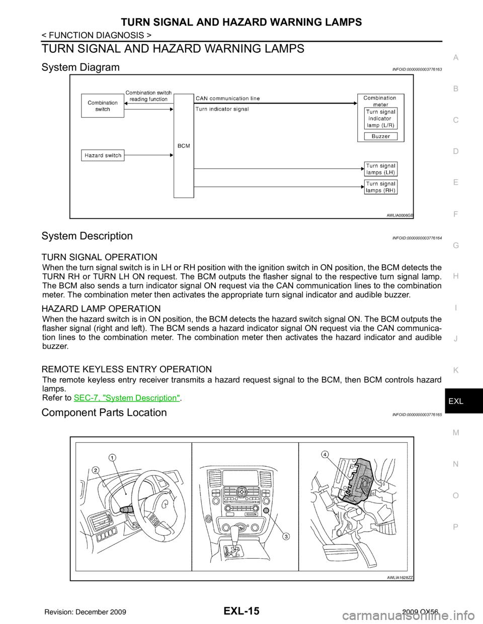
System DiagramINFOID:0000000003776163
System DescriptionINFOID:0000000003776164
TURN SIGNAL OPERATION
When the turn signal switch is in LH or RH position with the ignition switch in ON position, the BCM detects the
TURN RH or TURN LH ON request. The BCM outputs the fl asher signal to the respective turn signal lamp.
The BCM also sends a turn indicator signal ON reques t via the CAN communication lines to the combination
meter. The combination meter then activates the appropriate turn signal indicator and audible buzzer.
HAZARD LAMP OPERATION
When the hazard switch is in ON position, the BCM detects the hazard switch signal ON. The BCM outputs the
flasher signal (right and left). The BCM sends a hazar d indicator signal ON request via the CAN communica-
tion lines to the combination meter. The combinati on meter then activates the hazard indicator and audible
buzzer.
REMOTE KEYLESS ENTRY OPERATION
The remote keyless entry receiver transmits a hazard request signal to the BCM, then BCM controls hazard
lamps.
Refer to SEC-7, "
System Description".
Component Parts LocationINFOID:0000000003776165
AWLIA0006GB
AWLIA1628ZZ
Revision: December 20092009 QX56
Page 1965 of 4171
PARKING, LICENSE PLATE AND TAIL LAMPS
EXL-17
< FUNCTION DIAGNOSIS >
C
D E
F
G H
I
J
K
M A
B
EXL
N
O P
PARKING, LICENSE PLATE AND TAIL LAMPS
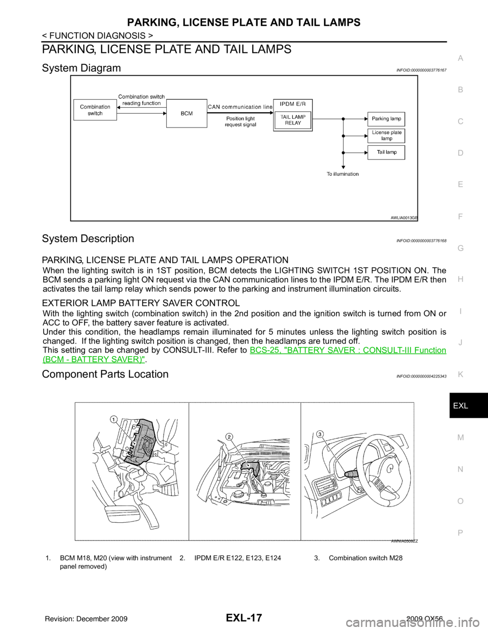
System DiagramINFOID:0000000003776167
System DescriptionINFOID:0000000003776168
PARKING, LICENSE PLATE AND TAIL LAMPS OPERATION
When the lighting switch is in 1ST position, BCM detects the LIGHTING SWITCH 1ST POSITION ON. The
BCM sends a parking light ON request via the CAN comm unication lines to the IPDM E/R. The IPDM E/R then
activates the tail lamp relay which sends power to the parking and instrument illumination circuits.
EXTERIOR LAMP BATTERY SAVER CONTROL
With the lighting switch (combination switch) in the 2nd position and the ignition switch is turned from ON or
ACC to OFF, the battery saver feature is activated.
Under this condition, the headlamps remain illuminated for 5 minutes unless the lighting switch position is
changed. If the lighting switch position is changed, then the headlamps are turned off.
This setting can be changed by CONSULT-III. Refer to BCS-25, "
BATTERY SAVER : CONSULT-III Function
(BCM - BATTERY SAVER)".
Component Parts LocationINFOID:0000000004225343
AWLIA0013GB
1. BCM M18, M20 (view with instrument
panel removed) 2. IPDM E/R E122, E123, E124 3. Combination switch M28
AWNIA0509ZZ
Revision: December 20092009 QX56
Page 1967 of 4171
TRAILER TOWEXL-19
< FUNCTION DIAGNOSIS >
C
DE
F
G H
I
J
K
M A
B
EXL
N
O P
TRAILER TOW
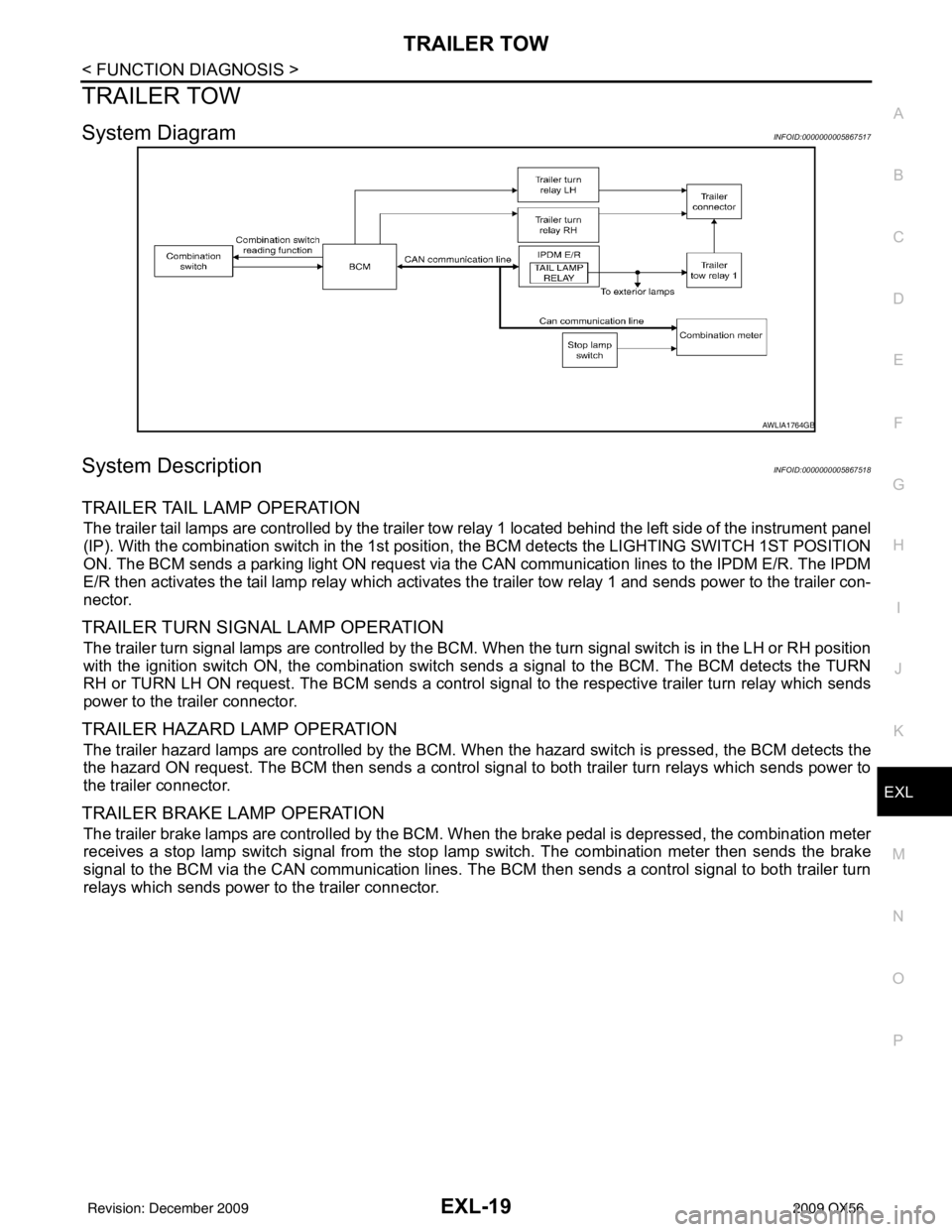
System DiagramINFOID:0000000005867517
System DescriptionINFOID:0000000005867518
TRAILER TAIL LAMP OPERATION
The trailer tail lamps are controlled by the trailer tow re lay 1 located behind the left side of the instrument panel
(IP). With the combination switch in the 1st position, the BCM detects the LI GHTING SWITCH 1ST POSITION
ON. The BCM sends a parking light ON request via the CAN communication lines to the IPDM E/R. The IPDM
E/R then activates the tail lamp relay which activates t he trailer tow relay 1 and sends power to the trailer con-
nector.
TRAILER TURN SIGNAL LAMP OPERATION
The trailer turn signal lamps are controlled by the BCM. When the turn signal switch is in the LH or RH position
with the ignition switch ON, the combination switch sends a signal to the BCM. The BCM detects the TURN
RH or TURN LH ON request. The BCM sends a control signal to the respective trailer turn relay which sends
power to the trailer connector.
TRAILER HAZARD LAMP OPERATION
The trailer hazard lamps are controlled by the BCM. When the hazard switch is pressed, the BCM detects the
the hazard ON request. The BCM then sends a control signal to both trailer turn relays which sends power to
the trailer connector.
TRAILER BRAKE LAMP OPERATION
The trailer brake lamps are controlled by the BCM. W hen the brake pedal is depressed, the combination meter
receives a stop lamp switch signal from the stop lamp switch. The combination meter then sends the brake
signal to the BCM via the CAN communication lines. The BCM then sends a control signal to both trailer turn
relays which sends power to the trailer connector.
AWLIA1764GB
Revision: December 20092009 QX56
Page 1970 of 4171

EXL-22
< FUNCTION DIAGNOSIS >
DIAGNOSIS SYSTEM (BCM)
DIAGNOSIS SYSTEM (BCM)
HEADLAMP
HEADLAMP : CONSULT-III Function (BCM - HEAD LAMP)INFOID:0000000004215497
WORK SUPPORT
*: Initial setting
DATA MONITOR
ACTIVE TEST
Work Item Setting itemSetting
BATTERY SAVER SET ON* With the exterior lamp battery saver function
OFF Without the exterior lamp battery saver function
CUSTOM A/LIGHT SET-
TING MODE1* Normal
MODE2 More sensitive setting than normal setting (Turns ON earlier than normal operation.)
MODE3 More sensitive setting than MODE 2 (Turns ON earlier than MODE 2.)
MODE4 Less sensitive setting than normal setting (Turns ON later than normal operation.)
ILL DELAY SET MODE1* 45 sec.
Sets delay timer function timer operation time
(All doors closed)
MODE2
Without the func-
tion
MODE3 30 sec.
MODE4 60 sec.
MODE5 90 sec.
MODE6 120 sec.
MODE7 150 sec.
MODE8 180 sec.
Monitor Item [Unit] Description
IGN ON SW [ON/OFF] Ignition switch (ON) status judged from IGN signal (ignition power supply)
HI BEAM SW [ON/OFF]
Each switch status that BCM judges from the combination switch reading function
H/L SW POS [ON/OFF]
LIGHT SW 1ST [ON/OFF]
PASSING SW [ON/OFF]
AUTO LIGHT SW [ON/OFF]
FR FOG SW [ON/OFF]
DOOR SW-DR [ON/OFF]
The switch status input from front door switch LH
AUT LIGHT SYS [ON/OFF] Auto light system status that BCM judges from the vehicle condition
Test ItemOperation Description
TA I L L A M P ON
Transmits the position light reques
t signal to IPDM E/R with CAN com-
munication to turn the tail lamp ON.
OFF Stops the tail lamp request signal transmission.
HEAD LAMP HI
Transmits the high beam request signal with CAN communication to turn
the headlamp (HI).
LO Transmits the low beam request signal with CAN communication to turn
the headlamp (LO).
OFF Stops the high & low beam request signal transmission.
Revision: December 20092009 QX56