2009 INFINITI QX56 clutch
[x] Cancel search: clutchPage 2245 of 4171
SQUEAK AND RATTLE TROUBLE DIAGNOSISGW-3
< SYMPTOM DIAGNOSIS >
C
DE
F
G H
I
J
L
M A
B
GW
N
O P
If possible, drive the vehicle with the customer until the noise is duplicated. Note any additional information on
the Diagnostic Worksheet regarding the conditions or lo cation of the noise. This information can be used to
duplicate the same conditions when you confirm the repair.
If the noise can be duplicated easily during the test drive, to help identify the source of the noise, try to dupli-
cate the noise with the vehicle stopped by doing one or all of the following:
1) Close a door.
2) Tap or push/pull around the area where the noise appears to be coming from.
3) Rev the engine.
4) Use a floor jack to recreate vehicle “twist”.
5) At idle, apply engine load (electrical load, half- clutch on M/T model, drive position on A/T model).
6) Raise the vehicle on a hoist and hit a tire with a rubber hammer.
• Drive the vehicle and attempt to duplicate the conditions the customer states exist when the noise occurs.
• If it is difficult to duplicate the noise, drive the vehicle slowly on an undulating or rough road to stress the vehicle body.
CHECK RELATED SERVICE BULLETINS
After verifying the customer concern or symptom, check ASIST for Technical Service Bulletins (TSBs) related
to that concern or symptom.
If a TSB relates to the symptom, follow the procedure to repair the noise.
LOCATE THE NOISE AND IDENTIFY THE ROOT CAUSE
1. Narrow down the noise to a general area.To help pinpoint the source of the noise, use a listening tool (Chassis Ear: J-39570, Engine Ear: J-39565 and mechanic's stethoscope).
2. Narrow down the noise to a more specific area and identify the cause of the noise by:
• removing the components in the area that you suspect the noise is coming from. Do not use too much force when removing clips and fasteners, otherwise clips and fasteners can be broken
or lost during the repair, resulting in the creation of new noise.
• tapping or pushing/pulling the component that you suspect is causing the noise.
Do not tap or push/pull the component with excessive force, otherwise the noise will be eliminated only tem-
porarily.
• feeling for a vibration with your hand by touching the component(s) that you suspect is (are) causing the
noise.
• placing a piece of paper between components that you suspect are causing the noise.
• looking for loose components and contact marks. Refer to GW-4, "
Generic Squeak and Rattle Troubleshooting".
REPAIR THE CAUSE
• If the cause is a loose component, tighten the component securely.
• If the cause is insufficient clearance between components:
- separate components by repositioning or loos ening and retightening the component, if possible.
- insulate components with a suitable insulator such as urethane pads, foam blocks, felt cloth tape or urethane tape. A NISSAN Squeak and Rattle Kit (J-43980) is available through your authorized NISSAN Parts Depart-
ment.
CAUTION:
Do not use excessive force as many components are constructed of plastic and may be damaged.
Always check with the Parts Department for the latest parts information.
The following materials are contained in the NISSAN Squeak and Rattle Kit (J-43980). Each item can be
ordered separately as needed.
URETHANE PADS [1.5 mm (0.059 in) thick]
Insulates connectors, harness, etc.
76268-9E005: 100 ×135 mm (3.94 ×5.31 in)/76884-71L01: 60 ×85 mm (2.36× 3.35 in)/76884-71L02: 15× 25
mm (0.59 ×0.98 in)
INSULATOR (Foam blocks)
Insulates components from contact. Can be used to fill space behind a panel.
73982-9E000: 45 mm (1.77 in) thick, 50× 50 mm (1.97×1.97 in)/73982-50Y00: 10 mm (0.39 in) thick,
50× 50 mm (1.97 ×1.97 in)
INSULATOR (Light foam block)
80845-71L00: 30 mm (1.18 in) thick, 30 ×50 mm (1.18 ×1.97 in)
FELT CLOTH TAPE
Used to insulate where movement does not occu r. Ideal for instrument panel applications.
Revision: December 20092009 QX56
Page 2265 of 4171

HA-1
VENTILATION, HEATER & AIR CONDITIONER
C
DE
F
G H
J
K L
M
SECTION HA
A
B
HA
N
O P
CONTENTS
HEATER & AIR CONDITIONING SYSTEM
PRECAUTION ................ ...............................3
PRECAUTIONS .............................................. .....3
Precaution for Supplemental Restraint System
(SRS) "AIR BAG" and "SEAT BELT PRE-TEN-
SIONER" ............................................................. ......
3
Precaution Necessary for Steering Wheel Rota-
tion After Battery Disconnect .....................................
3
Precaution for Working with HFC-134a (R-134a) ......4
Precaution for Procedure without Cowl Top Cover ......4
Contaminated Refrigerant .........................................4
General Refrigerant Precaution ................................5
Precaution for Leak Detection Dye ...........................5
A/C Identification Label .............................................5
Precaution for Refrigerant Connection ......................5
Precaution for Service of Compressor ....................10
Precaution for Service Equipment ...........................10
PREPARATION ...........................................13
PREPARATION .............................................. ....13
Special Service Tool ........................................... ....13
HFC-134a (R-134a) Service Tool and Equipment ....13
Commercial Service Tool ........................................16
FUNCTION DIAGNOSIS ..............................17
REFRIGERATION SYSTEM .......................... ....17
Refrigerant Cycle ................................................ ....17
Refrigerant System Protection ................................17
OIL ......................................................................19
Maintenance of Oil in Compressor ...................... ....19
ON-VEHICLE MAINTENANCE ....................20
REFRIGERATION SYSTEM .......................... ....20
HFC-134a (R-134a) Service Procedure .............. ....20
OIL ......................................................................22
Maintenance of Oil Quantity in Compressor ....... ....22
FLUORESCENT LEAK DETECTOR ................24
Checking of Refrigerant Leaks ............................ ....24
Checking System for Leaks Using the Fluorescent
Dye Leak Detector ...................................................
24
Dye Injection ............................................................24
ELECTRICAL LEAK DETECTOR ....................26
Checking of Refrigerant Leaks ................................26
Electronic Refrigerant Leak Detector .......................26
ON-VEHICLE REPAIR .................................29
REFRIGERATION SYSTEM .............................29
Component .......................................................... ....29
COMPRESSOR .................................................31
Removal and Installation for Compressor ...............31
Removal and Installation for Compressor Clutch ....32
LOW-PRESSURE FLEXIBLE HOSE ................36
Removal and Installation for Low-Pressure Flexi-
ble Hose ..................................................................
36
LOW-PRESSURE PIPE ....................................37
Removal and Installation for Low-Pressure Pipe .....37
Removal and Installation for Rear High- and Low-
Pressure A/C and Heater Core Pipes ......................
37
Removal and Installation for Underfloor Rear
High- and Low-Pressure A/C and Heater Core
Pipes ........................................................................
38
HIGH-PRESSURE FLEXIBLE HOSE ...............40
Removal and Installation for High-Pressure Flexi-
ble Hose ..................................................................
40
HIGH-PRESSURE PIPE ....................................41
Removal and Installation for High-Pressure Pipe ....41
Removal and Installation for Rear High- and Low-
Pressure A/C and Heater Core Pipes ......................
41
Removal and Installation for Underfloor Rear
High- and Low-Pressure A/C and Heater Core
Pipes ........................................................................
42
Revision: December 20092009 QX56
Page 2274 of 4171
HA-10
< PRECAUTION >
PRECAUTIONS
Precaution for Service of Compressor
INFOID:0000000003775293
Plug all openings to prevent moisture and foreign matter from entering.
When the compressor is removed, store it in th e same position as it is when mounted on the car.
When replacing or repairing compressor, follow “Maintenance of Oil Quantity in Compressor”
exactly. Refer to HA-22, "Maintenance of Oil Quantity in Compressor"
.
Keep friction surfaces between clut ch and pulley clean. If the surface is contaminated with oil, wipe
it off by using a clean waste cloth moistened with thinner.
After compressor service operation, turn the compressor shaft by hand more than 5 turns in both
directions. This will equally dist ribute oil inside the compressor. After the compressor is installed,
let the engine idle and oper ate the compressor for 1 hour.
After replacing the compressor magnet clutch, ap ply voltage to the new one and check for normal
operation. Refer to HA-32, "Removal and Installa tion for Compressor Clutch"
.
Precaution for Service EquipmentINFOID:0000000003775294
RECOVERY/RECYCLING EQUIPMENT
Follow the manufacturer's instructions for machi ne operation and machine maintenance. Never introduce any
refrigerant other than that specified into the machine.
ELECTRONIC LEAK DETECTOR
Follow the manufacturer's instructions for tester operation and tester maintenance.
VACUUM PUMP
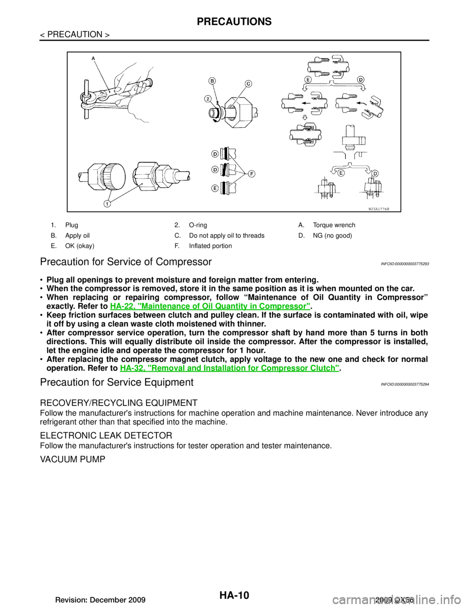
1. Plug 2. O-ring A. Torque wrench
B. Apply oil C. Do not apply oil to threads D. NG (no good)
E. OK (okay) F. Inflated portion
WJIA1774E
Revision: December 20092009 QX56
Page 2277 of 4171
PREPARATIONHA-13
< PREPARATION >
C
DE
F
G H
J
K L
M A
B
HA
N
O P
PREPARATION
PREPARATION
Special Service ToolINFOID:0000000003775295
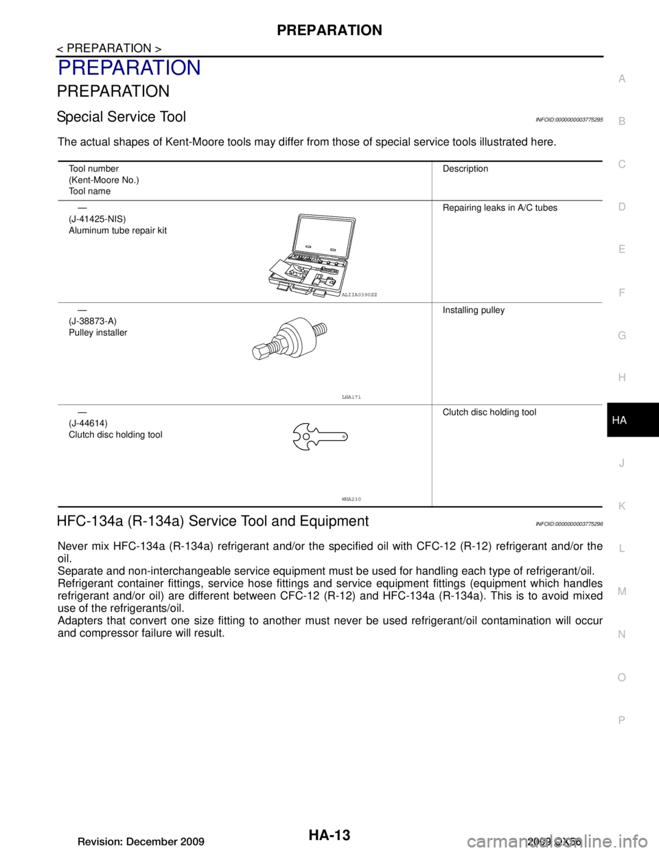
The actual shapes of Kent-Moore tools may differ fr om those of special service tools illustrated here.
HFC-134a (R-134a) Service Tool and EquipmentINFOID:0000000003775296
Never mix HFC-134a (R-134a) refrigerant and/or the spec ified oil with CFC-12 (R-12) refrigerant and/or the
oil.
Separate and non-interchangeable service equipment must be used for handling each type of refrigerant/oil.
Refrigerant container fittings, service hose fittings and service equipment fittings (equipment which handles
refrigerant and/or oil) are different between CFC-12 (R-12) and HFC-134a (R-134a). This is to avoid mixed
use of the refrigerants/oil.
Adapters that convert one size fitti ng to another must never be used refrigerant/oil contamination will occur
and compressor failure will result.
Tool number
(Kent-Moore No.)
Tool name Description
—
(J-41425-NIS)
Aluminum tube repair kit Repairing leaks in A/C tubes
—
(J-38873-A)
Pulley installer Installing pulley
—
(J-44614)
Clutch disc holding tool Clutch disc holding tool
ALIIA0390ZZ
LHA171
WHA230
Revision: December 20092009 QX56
Page 2281 of 4171

REFRIGERATION SYSTEMHA-17
< FUNCTION DIAGNOSIS >
C
DE
F
G H
J
K L
M A
B
HA
N
O P
FUNCTION DIAGNOSIS
REFRIGERATION SYSTEM
Refrigerant CycleINFOID:0000000003775298
REFRIGERANT FLOW
The refrigerant flows in the standard pattern, that is , through the compressor, the condenser with liquid tank,
through the front and rear evaporators, and back to the compressor. The refrigerant evaporation through the
evaporator coils are controlled by fr ont and rear externally equalized expansion valves, located inside the front
and rear evaporator cases.
Refrigerant System ProtectionINFOID:0000000003775299
REFRIGERANT PRESSURE SENSOR
The refrigerant system is protected against excessively hi gh or low pressures by the refrigerant pressure sen-
sor, located on the condenser. If the system pressure rise s above or falls below the specifications, the refriger-
ant pressure sensor detects the pressure inside the refrigerant line and sends a voltage signal to the ECM.
The ECM de-energizes the A/C relay to disengage the magnet ic compressor clutch when pressure on the high
pressure side detected by refrigerant pressu re sensor is over about 2,746 kPa (28 kg/cm
2, 398 psi), or below
about 120 kPa (1.22 kg/cm
2, 17.4 psi).
PRESSURE RELIEF VALVE
The refrigerant system is also protected by a pressure relief valve, located in the rear head of the compressor.
When the pressure of refrigerant in the system incr eases to an abnormal level [more than 2,990 kPa (30.5 kg/
Revision: December 20092009 QX56
Page 2296 of 4171
HA-32
< ON-VEHICLE REPAIR >
COMPRESSOR
Replace the O-rings of the low-pressure flexible hose and high-pressure flexible hose with new
ones, apply compressor oil to the O-rings when installing them.
After recharging the A/C system with refrigerant, check for leaks.
Removal and Installation for Compressor ClutchINFOID:0000000003775310
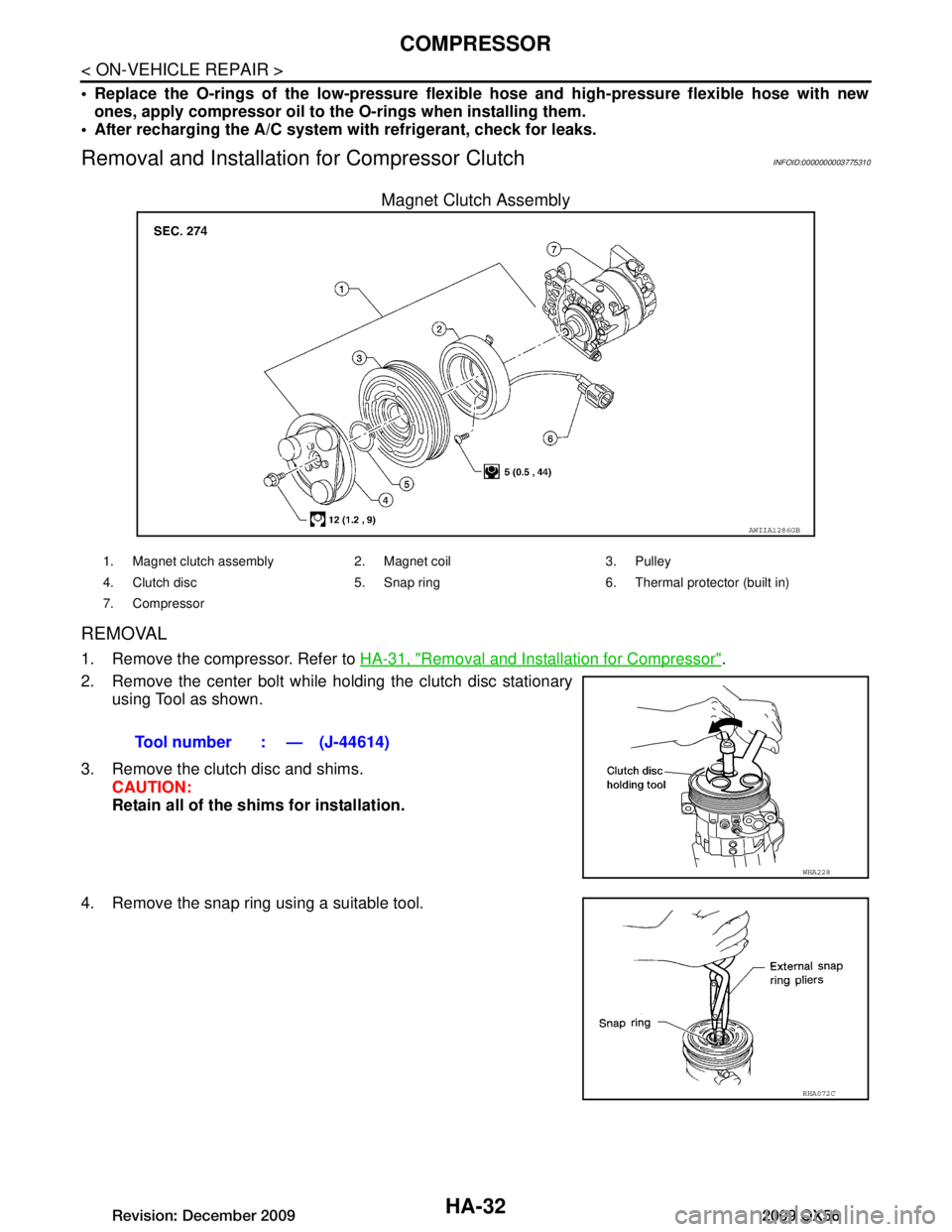
Magnet Clutch Assembly
REMOVAL
1. Remove the compressor. Refer to HA-31, "Removal and Installation for Compressor".
2. Remove the center bolt while holding the clutch disc stationary using Tool as shown.
3. Remove the clutch disc and shims. CAUTION:
Retain all of the shims for installation.
4. Remove the snap ring using a suitable tool.
AWIIA1286GB
1. Magnet clutch assembly 2. Magnet coil 3. Pulley
4. Clutch disc 5. Snap ring 6. Thermal protector (built in)
7. Compressor
Tool number : — (J-44614)
WHA228
RHA072C
Revision: December 20092009 QX56
Page 2297 of 4171
COMPRESSORHA-33
< ON-VEHICLE REPAIR >
C
DE
F
G H
J
K L
M A
B
HA
N
O P
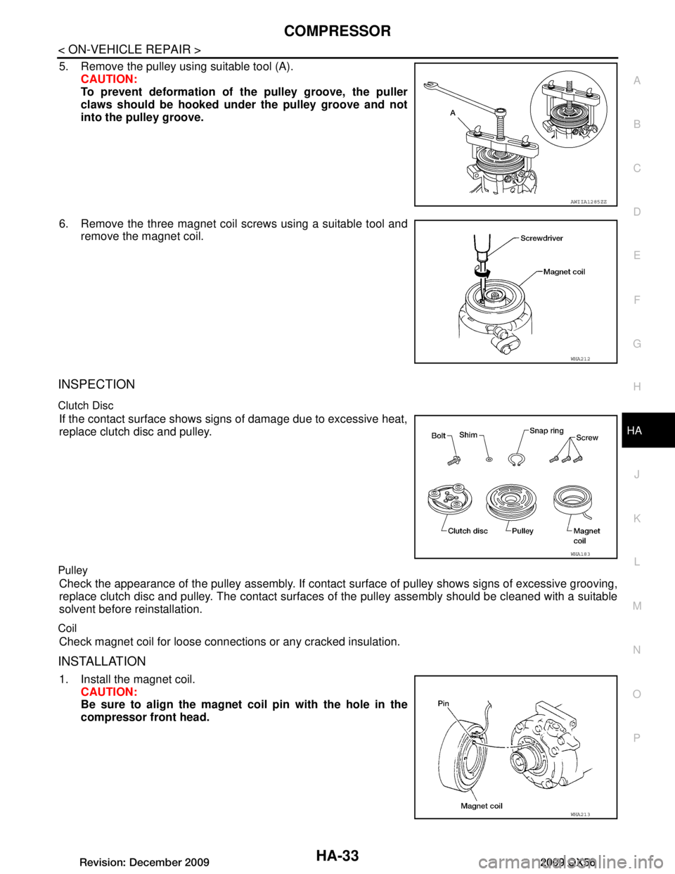
5. Remove the pulley using suitable tool (A). CAUTION:
To prevent deformation of th e pulley groove, the puller
claws should be hooked un der the pulley groove and not
into the pulley groove.
6. Remove the three magnet coil screws using a suitable tool and remove the magnet coil.
INSPECTION
Clutch Disc
If the contact surface shows si gns of damage due to excessive heat,
replace clutch disc and pulley.
Pulley
Check the appearance of the pulley assembly. If contact surface of pulley shows signs of excessive grooving,
replace clutch disc and pulley. The contact surfaces of the pulley assembly should be cleaned with a suitable
solvent before reinstallation.
Coil
Check magnet coil for loose connections or any cracked insulation.
INSTALLATION
1. Install the magnet coil. CAUTION:
Be sure to align the magnet co il pin with the hole in the
compressor front head.
AWIIA1285ZZ
WHA212
WHA183
WHA213
Revision: December 20092009 QX56
Page 2298 of 4171
HA-34
< ON-VEHICLE REPAIR >
COMPRESSOR
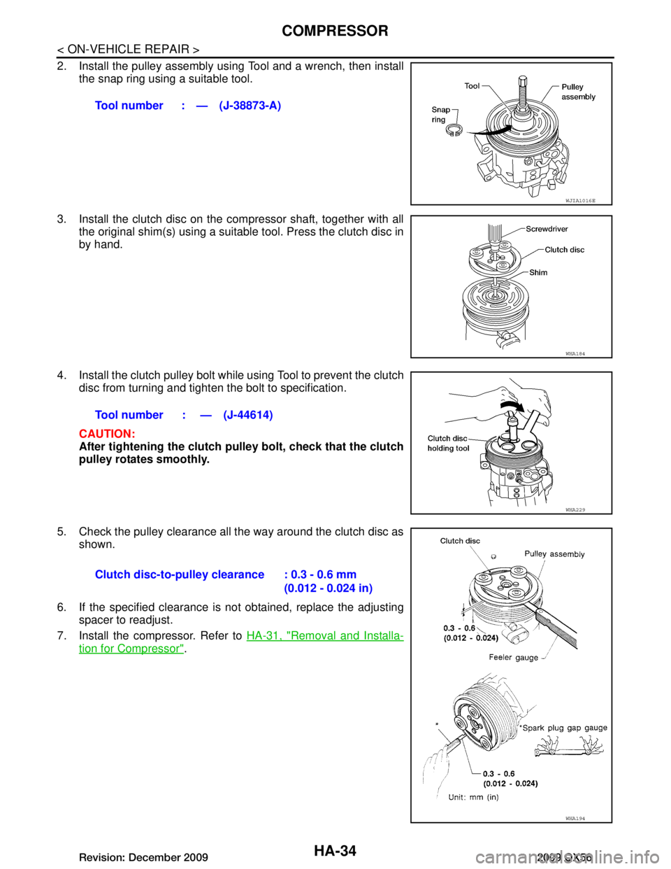
2. Install the pulley assembly using Tool and a wrench, then installthe snap ring using a suitable tool.
3. Install the clutch disc on the compressor shaft, together with all the original shim(s) using a suitabl e tool. Press the clutch disc in
by hand.
4. Install the clutch pulley bolt while using Tool to prevent the clutch
disc from turning and tighten the bolt to specification.
CAUTION:
After tightening the clutch pu lley bolt, check that the clutch
pulley rotates smoothly.
5. Check the pulley clearance all the way around the clutch disc as shown.
6. If the specified clearance is not obtained, replace the adjusting spacer to readjust.
7. Install the compressor. Refer to HA-31, "Removal and Installa-
tion for Compressor".
Tool number : — (J-38873-A)
WJIA1016E
WHA184
Tool number : — (J-44614)
WHA229
Clutch disc-to-pulley clearance : 0.3 - 0.6 mm
(0.012 - 0.024 in)
WHA194
Revision: December 20092009 QX56