2009 INFINITI QX56 turn signal
[x] Cancel search: turn signalPage 3790 of 4171
TM-142
< SYMPTOM DIAGNOSIS >
SYSTEM SYMPTOM
DIAGNOSTIC PROCEDURE
1.CHECK SELF-DIAGNOSTIC RESULTS
Perform self-diagnosis. Refer to TM-32, "CONSULT-III Function (TRANSMISSION)"
.
Do the self-diagnostic results indicate torque conv erter clutch solenoid valve, engine speed signal, input
speed sensor, CAN communication?
YES >> Check the malfunctioning system. Refer to TM-64, "Diagnosis Procedure", TM-52, "Diagnosis
Procedure", TM-47, "Diagnosis Procedure", TM-39, "Diagnosis Procedure".
NO >> GO TO 2.
2.CHECK SYMPTOM
Check again. Refer to TM-191, "Cruise Test - Part 1"
.
OK or NG
OK >> INSPECTION END
NG >> GO TO 3.
3.PERFORM TCM INSPECTION
1. Perform TCM input/output signals inspection. Refer to TM-104, "Reference Value"
.
2. If NG, recheck A/T assembly harness connector terminals for damage or loose connection with harness
connector.
OK or NG
OK >> INSPECTION END
NG >> Repair or replace damaged parts.
Engine Speed Does Not Return to IdleINFOID:0000000003772006
SYMPTOM:
When a shift-down is performed, the engine speed does not smoothly return to the idling speed.
DIAGNOSTIC PROCEDURE
1.CHECK A/T FLUID LEVEL
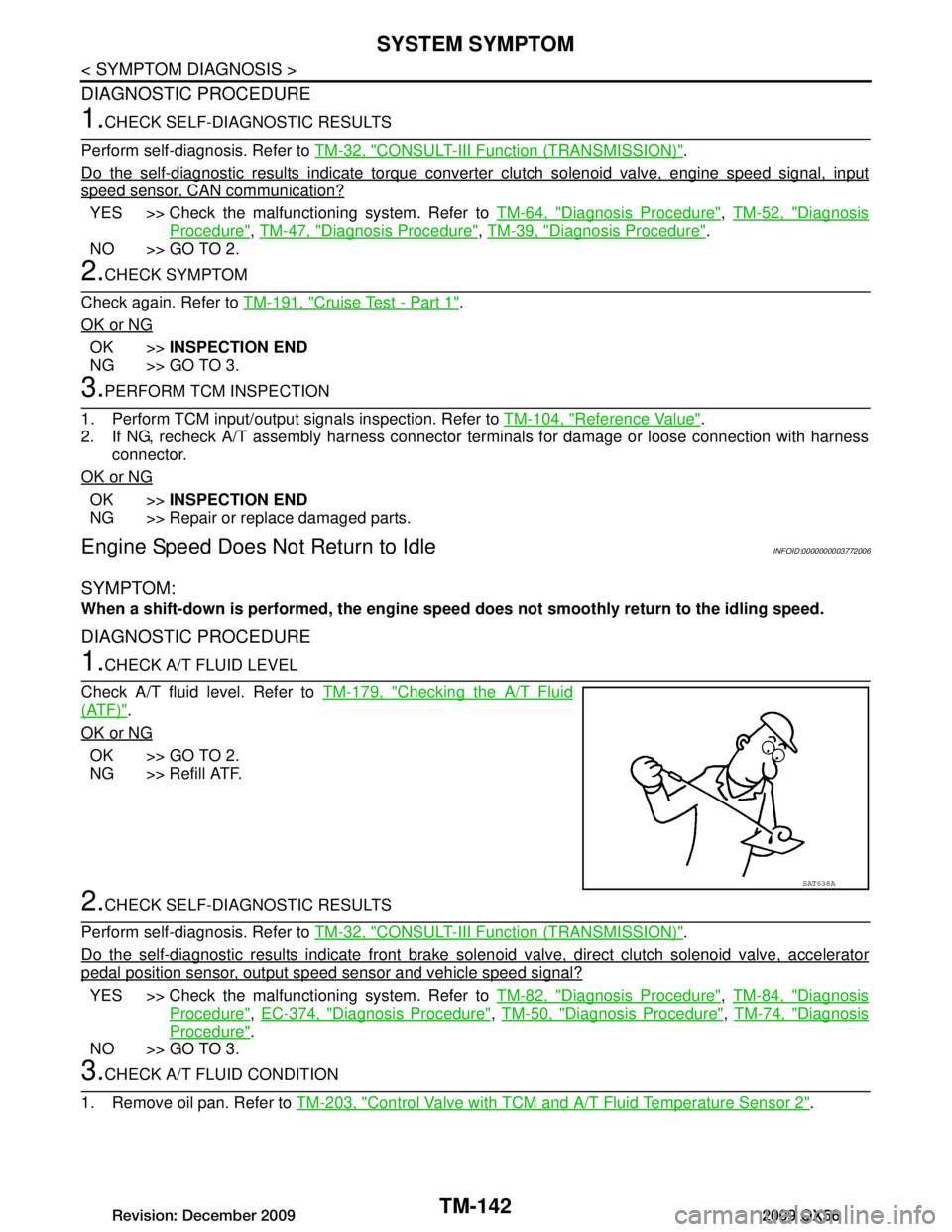
Check A/T fluid level. Refer to TM-179, "Checking the A/T Fluid
(ATF)".
OK or NG
OK >> GO TO 2.
NG >> Refill ATF.
2.CHECK SELF-DIAGNOSTIC RESULTS
Perform self-diagnosis. Refer to TM-32, "CONSULT-III Function (TRANSMISSION)"
.
Do the self-diagnostic results indicate front brake sol enoid valve, direct clutch solenoid valve, accelerator
pedal position sensor, output speed sensor and vehicle speed signal?
YES >> Check the malfunctioning system. Refer to TM-82, "Diagnosis Procedure", TM-84, "Diagnosis
Procedure", EC-374, "Diagnosis Procedure", TM-50, "Diagnosis Procedure", TM-74, "Diagnosis
Procedure".
NO >> GO TO 3.
3.CHECK A/T FLUID CONDITION
1. Remove oil pan. Refer to TM-203, "Control Valve with TCM and A/T Fluid Temperature Sensor 2"
.
SAT638A
Revision: December 20092009 QX56
Page 3791 of 4171
SYSTEM SYMPTOMTM-143
< SYMPTOM DIAGNOSIS >
CEF
G H
I
J
K L
M A
B
TM
N
O P
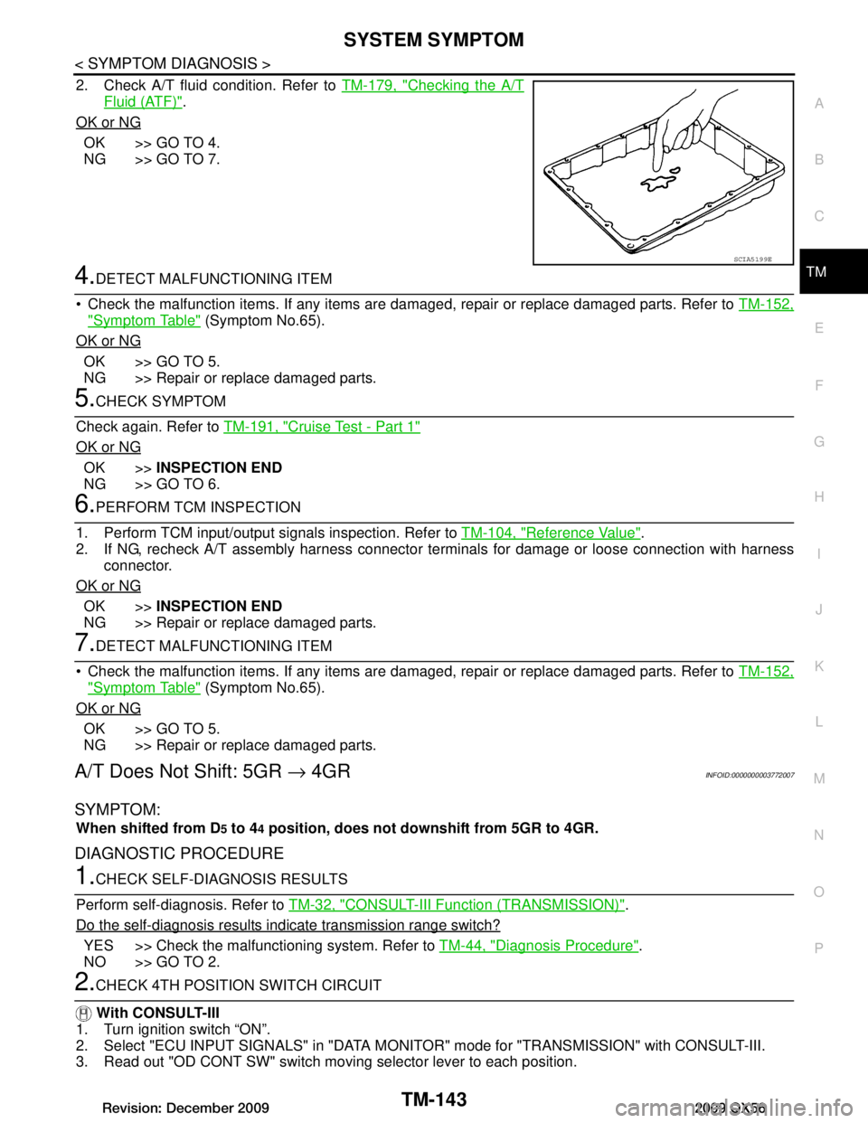
2. Check A/T fluid condition. Refer to TM-179, "Checking the A/T
Fluid (ATF)".
OK or NG
OK >> GO TO 4.
NG >> GO TO 7.
4.DETECT MALFUNCTIONING ITEM
Check the malfunction items. If any items are damaged, repair or replace damaged parts. Refer to TM-152,
"Symptom Table" (Symptom No.65).
OK or NG
OK >> GO TO 5.
NG >> Repair or replace damaged parts.
5.CHECK SYMPTOM
Check again. Refer to TM-191, "Cruise Test - Part 1"
OK or NG
OK >>INSPECTION END
NG >> GO TO 6.
6.PERFORM TCM INSPECTION
1. Perform TCM input/output signals inspection. Refer to TM-104, "Reference Value"
.
2. If NG, recheck A/T assembly harness connector terminals for damage or loose connection with harness
connector.
OK or NG
OK >> INSPECTION END
NG >> Repair or replace damaged parts.
7.DETECT MALFUNCTIONING ITEM
Check the malfunction items. If any items are damaged, repair or replace damaged parts. Refer to TM-152,
"Symptom Table" (Symptom No.65).
OK or NG
OK >> GO TO 5.
NG >> Repair or replace damaged parts.
A/T Does Not Shift: 5GR → 4GRINFOID:0000000003772007
SYMPTOM:
When shifted from D5 to 44 position, does not downshift from 5GR to 4GR.
DIAGNOSTIC PROCEDURE
1.CHECK SELF-DIAGNOSIS RESULTS
Perform self-diagnosis. Refer to TM-32, "CONSULT-III Function (TRANSMISSION)"
.
Do the self-diagnosis results i ndicate transmission range switch?
YES >> Check the malfunctioning system. Refer to TM-44, "Diagnosis Procedure".
NO >> GO TO 2.
2.CHECK 4TH POSITION SWITCH CIRCUIT
With CONSULT-III
1. Turn ignition switch “ON”.
2. Select "ECU INPUT SIGNALS" in "DATA MONITO R" mode for "TRANSMISSION" with CONSULT-III.
3. Read out "OD CONT SW" switch moving selector lever to each position.
SCIA5199E
Revision: December 20092009 QX56
Page 3796 of 4171
TM-148
< SYMPTOM DIAGNOSIS >
SYSTEM SYMPTOM
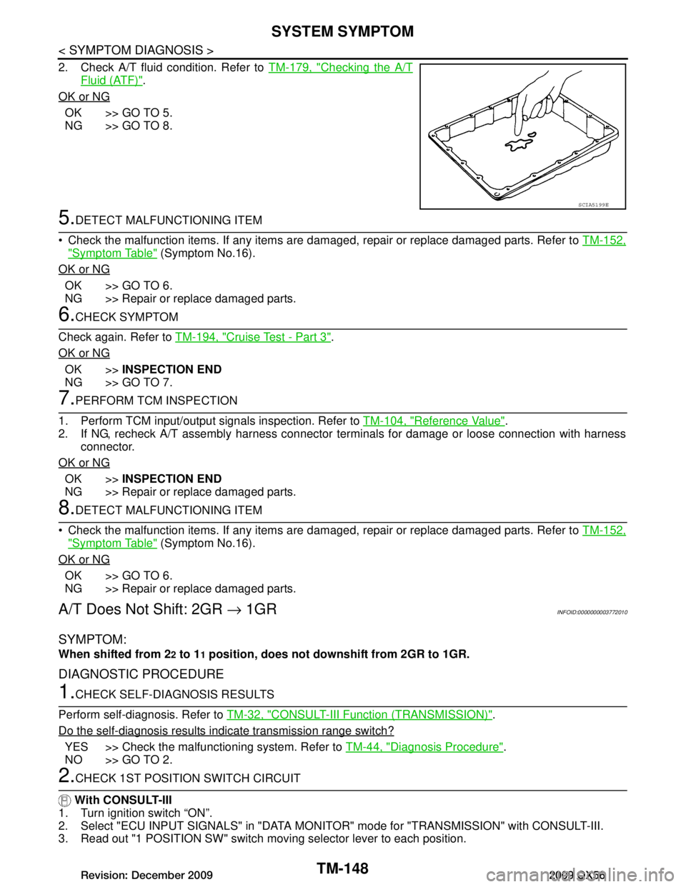
2. Check A/T fluid condition. Refer to TM-179, "Checking the A/T
Fluid (ATF)".
OK or NG
OK >> GO TO 5.
NG >> GO TO 8.
5.DETECT MALFUNCTIONING ITEM
Check the malfunction items. If any items are dam aged, repair or replace damaged parts. Refer to TM-152,
"Symptom Table" (Symptom No.16).
OK or NG
OK >> GO TO 6.
NG >> Repair or replace damaged parts.
6.CHECK SYMPTOM
Check again. Refer to TM-194, "Cruise Test - Part 3"
.
OK or NG
OK >> INSPECTION END
NG >> GO TO 7.
7.PERFORM TCM INSPECTION
1. Perform TCM input/output signals inspection. Refer to TM-104, "Reference Value"
.
2. If NG, recheck A/T assembly harness connector terminals for damage or loose connection with harness
connector.
OK or NG
OK >> INSPECTION END
NG >> Repair or replace damaged parts.
8.DETECT MALFUNCTIONING ITEM
Check the malfunction items. If any items are dam aged, repair or replace damaged parts. Refer to TM-152,
"Symptom Table" (Symptom No.16).
OK or NG
OK >> GO TO 6.
NG >> Repair or replace damaged parts.
A/T Does Not Shift: 2GR → 1GRINFOID:0000000003772010
SYMPTOM:
When shifted from 22 to 11 position, does not down shift from 2GR to 1GR.
DIAGNOSTIC PROCEDURE
1.CHECK SELF-DIAGNOSIS RESULTS
Perform self-diagnosis. Refer to TM-32, "CONSULT-III Function (TRANSMISSION)"
.
Do the self-diagnosis results indicate transmission range switch?
YES >> Check the malfunctioning system. Refer to TM-44, "Diagnosis Procedure".
NO >> GO TO 2.
2.CHECK 1ST POSITION SWITCH CIRCUIT
With CONSULT-III
1. Turn ignition switch “ON”.
2. Select "ECU INPUT SIGNALS" in "DATA MONITO R" mode for "TRANSMISSION" with CONSULT-III.
3. Read out "1 POSITION SW" switch moving selector lever to each position.
SCIA5199E
Revision: December 20092009 QX56
Page 3798 of 4171
TM-150
< SYMPTOM DIAGNOSIS >
SYSTEM SYMPTOM
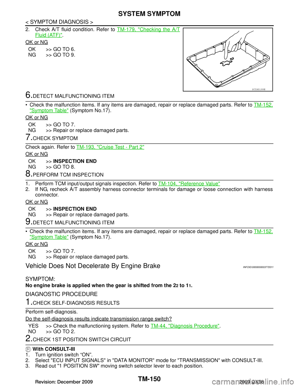
2. Check A/T fluid condition. Refer to TM-179, "Checking the A/T
Fluid (ATF)".
OK or NG
OK >> GO TO 6.
NG >> GO TO 9.
6.DETECT MALFUNCTIONING ITEM
Check the malfunction items. If any items are dam aged, repair or replace damaged parts. Refer to TM-152,
"Symptom Table" (Symptom No.17).
OK or NG
OK >> GO TO 7.
NG >> Repair or replace damaged parts.
7.CHECK SYMPTOM
Check again. Refer to TM-193, "Cruise Test - Part 2"
OK or NG
OK >>INSPECTION END
NG >> GO TO 8.
8.PERFORM TCM INSPECTION
1. Perform TCM input/output signals inspection. Refer to TM-104, "Reference Value"
2. If NG, recheck A/T assembly harness connector terminals for damage or loose connection with harness
connector.
OK or NG
OK >> INSPECTION END
NG >> Repair or replace damaged parts.
9.DETECT MALFUNCTIONING ITEM
Check the malfunction items. If any items are dam aged, repair or replace damaged parts. Refer to TM-152,
"Symptom Table" (Symptom No.17).
OK or NG
OK >> GO TO 7.
NG >> Repair or replace damaged parts.
Vehicle Does Not Decele rate By Engine BrakeINFOID:0000000003772011
SYMPTOM:
No engine brake is applied when the gear is shifted from the 22 to 11.
DIAGNOSTIC PROCEDURE
1.CHECK SELF-DIAGNOSIS RESULTS
Perform self-diagnosis.
Do the self-diagnosis results indicate transmission range switch?
YES >> Check the malfunctioning system. Refer to TM-44, "Diagnosis Procedure".
NO >> GO TO 2.
2.CHECK 1ST POSITION SWITCH CIRCUIT
With CONSULT-III
1. Turn ignition switch “ON”.
2. Select "ECU INPUT SIGNALS" in "DATA MONITO R" mode for "TRANSMISSION" with CONSULT-III.
3. Read out "1 POSITION SW" moving switch selector lever to each position.
SCIA5199E
Revision: December 20092009 QX56
Page 3821 of 4171
SYSTEM SYMPTOMTM-173
< SYMPTOM DIAGNOSIS >
CEF
G H
I
J
K L
M A
B
TM
N
O P
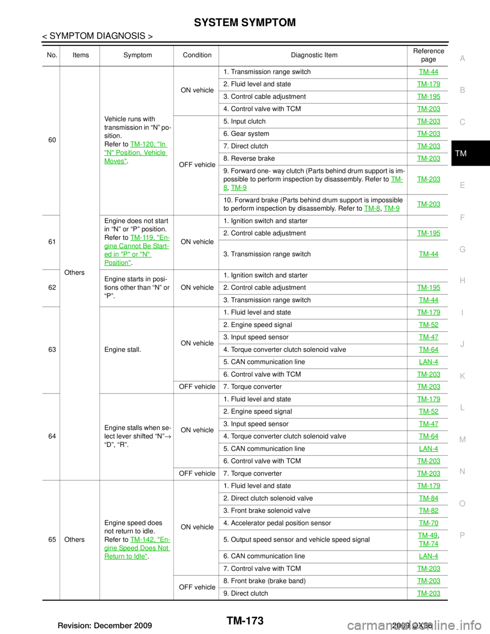
60
Others Vehicle runs with
transmission in “N” po-
sition.
Refer to
TM-120, "In
"N" Position, Vehicle
Moves". ON vehicle
1. Transmission range switch
TM-44
2. Fluid level and stateTM-179
3. Control cable adjustmentTM-195
4. Control valve with TCMTM-203
OFF vehicle5. Input clutch
TM-203
6. Gear systemTM-203
7. Direct clutchTM-203
8. Reverse brakeTM-203
9. Forward one- way clutch (Parts behind drum support is im-
possible to perform inspection by disassembly. Refer to TM-
8, TM-9
TM-203
10. Forward brake (Parts behind drum support is impossible
to perform inspection by disassembly. Refer to TM-8
, TM-9TM-203
61 Engine does not start
in “N” or “P” position.
Refer to
TM-119, "En-gine Cannot Be Start-
ed in "P" or "N"
Position". ON vehicle1. Ignition switch and starter
2. Control cable adjustment
TM-195
3. Transmission range switch TM-44
62Engine starts in posi-
tions other than “N” or
“P”.
ON vehicle1. Ignition switch and starter
2. Control cable adjustment
TM-195
3. Transmission range switch TM-44
63 Engine stall.ON vehicle1. Fluid level and state
TM-179
2. Engine speed signal TM-52
3. Input speed sensorTM-47
4. Torque converter clutch solenoid valveTM-64
5. CAN communication line LAN-4
6. Control valve with TCMTM-203
OFF vehicle 7. Torque converter TM-203
64Engine stalls when se-
lect lever shifted “N”
→
“D”, “R”. ON vehicle1. Fluid level and state
TM-179
2. Engine speed signal TM-52
3. Input speed sensorTM-47
4. Torque converter clutch solenoid valveTM-64
5. CAN communication line LAN-4
6. Control valve with TCMTM-203
OFF vehicle 7. Torque converter TM-203
65 OthersEngine speed does
not return to idle.
Refer to
TM-142, "En-
gine Speed Does Not
Return to Idle". ON vehicle 1. Fluid level and state
TM-179
2. Direct clutch solenoid valve TM-84
3. Front brake solenoid valveTM-82
4. Accelerator pedal position sensorTM-70
5. Output speed sensor and vehicle speed signalTM-49,
TM-74
6. CAN communication line LAN-4
7. Control valve with TCMTM-203
OFF vehicle8. Front brake (brake band)
TM-2039. Direct clutchTM-203
No. Items Symptom Condition Diagnostic Item Reference
page
Revision: December 20092009 QX56
Page 3841 of 4171
ROAD TESTTM-193
< ON-VEHICLE MAINTENANCE >
CEF
G H
I
J
K L
M A
B
TM
N
O P
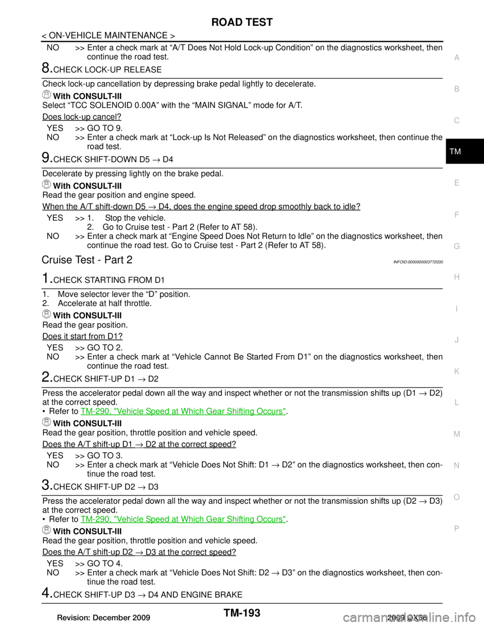
NO >> Enter a check mark at “A/T Does Not Hold Lock-up Condition” on the diagnostics worksheet, then
continue the road test.
8.CHECK LOCK-UP RELEASE
Check lock-up cancellation by depressi ng brake pedal lightly to decelerate.
With CONSULT-III
Select “TCC SOLENOID 0.00A” with the “MAIN SIGNAL” mode for A/T.
Does lock-up cancel?
YES >> GO TO 9.
NO >> Enter a check mark at “Lock-up Is Not Rel eased” on the diagnostics worksheet, then continue the
road test.
9.CHECK SHIFT-DOWN D5 → D4
Decelerate by pressing lightly on the brake pedal. With CONSULT-III
Read the gear position and engine speed.
When the A/T shift-down D5
→ D4, does the engine speed drop smoothly back to idle?
YES >> 1. Stop the vehicle. 2. Go to Cruise test - Part 2 (Refer to AT 58).
NO >> Enter a check mark at “Engine Speed Does Not Return to Idle” on the diagnostics worksheet, then continue the road test. Go to Cruise test - Part 2 (Refer to AT 58).
Cruise Test - Part 2INFOID:0000000003772030
1.CHECK STARTING FROM D1
1. Move selector lever the “D” position.
2. Accelerate at half throttle. With CONSULT-III
Read the gear position.
Does it start from D1?
YES >> GO TO 2.
NO >> Enter a check mark at “Vehicle Cannot Be St arted From D1” on the diagnostics worksheet, then
continue the road test.
2.CHECK SHIFT-UP D1 → D2
Press the accelerator pedal down all the way and inspect whether or not the transmission shifts up (D1 → D2)
at the correct speed.
Refer to TM-290, "Vehicle Speed at Which Gear Shifting Occurs"
.
With CONSULT-III
Read the gear position, thrott le position and vehicle speed.
Does the A/T shift-up D1
→ D2 at the correct speed?
YES >> GO TO 3.
NO >> Enter a check mark at “Vehicle Does Not Shift: D1 → D2” on the diagnostics worksheet, then con-
tinue the road test.
3.CHECK SHIFT-UP D2 → D3
Press the accelerator pedal down all the way and inspect whether or not the transmission shifts up (D2 → D3)
at the correct speed.
Refer to TM-290, "Vehicle Speed at Which Gear Shifting Occurs"
.
With CONSULT-III
Read the gear position, thrott le position and vehicle speed.
Does the A/T shift-up D2
→ D3 at the correct speed?
YES >> GO TO 4.
NO >> Enter a check mark at “Vehicle Does Not Shift: D2 → D3” on the diagnostics worksheet, then con-
tinue the road test.
4.CHECK SHIFT-UP D3 → D4 AND ENGINE BRAKE
Revision: December 20092009 QX56
Page 3985 of 4171
WCS-8
< FUNCTION DIAGNOSIS >
WARNING CHIME SYSTEM
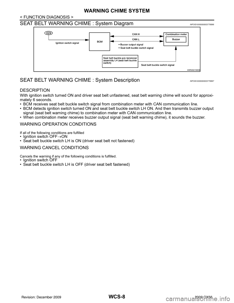
SEAT BELT WARNING CHIME : System Diagram
INFOID:0000000003776696
SEAT BELT WARNING CHIME : System DescriptionINFOID:0000000003776697
DESCRIPTION
With ignition switch turned ON and driver seat belt unfastened, seat belt warning chime will sound for approxi-
mately 6 seconds.
• BCM receives seat belt buckle switch signal from combination meter with CAN communication line.
• BCM detects ignition switch turned ON and seat belt buckle switch LH ON. And then transmits buzzer output signal (seat belt warning chime) to combination meter with CAN communication line.
• When combination meter receives buzzer output signal (seat belt warning chime), it sounds the buzzer.
WARNING OPERATION CONDITIONS
If all of the following conditions are fulfilled• Ignition switch OFF→ON
• Seat belt buckle switch LH is ON (driver seat belt not fastened)
WARNING CANCEL CONDITIONS
Cancels the warning if any of the following conditions is fulfilled.
• Ignition switch OFF
• Seat belt buckle switch LH is OFF (driver seat belt fastened)
AWNIA0156GB
Revision: December 20092009 QX56
Page 3989 of 4171

WCS-12
< FUNCTION DIAGNOSIS >
DIAGNOSIS SYSTEM (METER)
DIAGNOSIS SYSTEM (METER)
CONSULT-III Function (METER/M&A)INFOID:0000000004115456
CONSULT-III can display each diagnostic item using the diagnostic test modes shown following.
SELF-DIAG RESULTS
Display Item List
Refer to WCS-47, "DTC Index".
DATA MONITOR
Display Item List
X: Applicable
METER/M&A diagnosis mode Description
SELF-DIAG RESULTS Displays combination meter self-diagnosis results. DATA MONITOR Displays combination meter input/output data in real time.
CAN DIAG SUPPORT MNTR The result of transmit/receive diagnosis of CAN communication can be read.
Display item [Unit] MAIN
SIGNALS SELECTION
FROM MENU Description
SPEED METER [km/h] or [mph] X X Displays the value of vehicle speed signal.
SPEED OUTPUT [km/h] or [mph] X XDisplays the value of vehicle speed signal, which is transmitted to
each unit with
CAN communication.
TACHO METER [rpm] XX Displays the value of engine speed signal, which is input from ECM.
FUEL METER [lit.] XXDisplays the value, which processes a resistance signal from fuel
gauge.
W TEMP METER [ °C] or [° F] X XDisplays the value of engine coolant temperature signal, which is in-
put from ECM.
ABS W/L [ON/OFF] X Displays [ON/OFF] condition of ABS warning lamp.
VDC/TCS IND [ON/OFF] X Displays [ON/OFF] condition of VDC OFF indicator lamp.
SLIP IND [ON/OFF] X Displays [ON/OFF] condition of SLIP indicator lamp.
BRAKE W/L [ON/OFF] X Displays [ON/OFF] condition of brake warning lamp.*
DOOR W/L [ON/OFF] X Displays [ON/OFF] condition of door warning lamp.
TRUNK W/L [ON/OFF] X Displays [ON/OFF] condition of glass hatch warning lamp.
HI-BEAM IND [ON/OFF] X Displays [ON/OFF] condition of high beam indicator.
TURN IND [ON/OFF] X Displays [ON/OFF] conditio n of turn indicator.
OIL W/L [ON/OFF] X Displays [ON/OFF] condition of oil pressure warning lamp.
C-ENG W/L [ON/OFF] X Displays [ON/OFF] condition of malfunction indicator lamp.
CRUISE IND [ON/OFF] X Displays [ON/OFF] condition of CRUISE indicator.
SET IND [ON/OFF] X Displays [ON/OFF] condition of SET indicator.
AT CHECK W/L [ON/OFF] X Displays [ON/OFF] condition of AT CHECK warning lamp.
FUEL W/L [ON/OFF] XX Displays [ON/OFF] condition of low-fuel warning lamp.
AIR PRES W/L [ON/OFF] X Displays [ON/OFF] condition of tire pressure warning lamp.
KEY G W/L [ON/OFF] X Displays [ON/OFF] condition of key green warning lamp.
KEY R W/L [ON/OFF] X Displays [ON/OFF] condition of key red warning lamp.
KEY KNOB W/L [ON/OFF] X Displays [ON/OFF] condition of key knob warning lamp.
M RANGE SW [ON/OFF] XX Displays [ON/OFF] condition of manual mode range switch.
NM RANGE SW [ON/OFF] XXDisplays [ON/OFF] condition of except for manual mode range
switch.
AT SFT UP SW [ON/OFF] XX Displays [ON/OFF] condition of A/T shift-up switch.
Revision: December 20092009 QX56