2009 INFINITI QX56 turn signal
[x] Cancel search: turn signalPage 4031 of 4171
WCS-54
< ECU DIAGNOSIS >
BCM (BODY CONTROL MODULE)
28 L/R Front blower monitor Input ONFront blower motor OFF
Battery voltage
Front blower motor ON 0V
29 W/B Hazard switch Input OFFON
0V
OFF 5V
30 Y/BR Glass hatch switch Input OFF Glass hatch switch released
0
Glass hatch switch pressed Battery
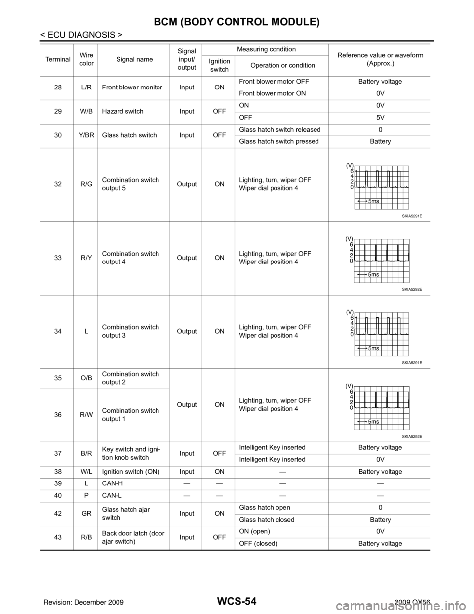
32 R/G Combination switch
output 5
Output ONLighting, turn, wiper OFF
Wiper dial position 4
33 R/Y Combination switch
output 4 Output ONLighting, turn, wiper OFF
Wiper dial position 4
34 L Combination switch
output 3 Output ON
Lighting, turn, wiper OFF
Wiper dial position 4
35 O/B Combination switch
output 2
Output ONLighting, turn, wiper OFF
Wiper dial position 4
36 R/W Combination switch
output 1
37 B/R Key switch and igni-
tion knob switch Input OFFIntelligent Key inserted
Battery voltage
Intelligent Key inserted 0V
38 W/L Ignition switch (ON) Input ON —Battery voltage
39 L CAN-H — —— —
40 P CAN-L — —— —
42 GR Glass hatch ajar
switch Input ONGlass hatch open
0
Glass hatch closed Battery
43 R/B Back door latch (door
ajar switch) Input OFFON (open)
0V
OFF (closed) Battery voltage
Te r m i n a l
Wire
color Signal name Signal
input/
output Measuring condition
Reference value or waveform
(Approx.)
Ignition
switch Operation or condition
SKIA5291E
SKIA5292E
SKIA5291E
SKIA5292E
Revision: December 20092009 QX56
Page 4032 of 4171
WCS
BCM (BODY CONTROL MODULE)WCS-55
< ECU DIAGNOSIS >
C
DE
F
G H
I
J
K L
M B A
O P44 O Rear wiper auto stop
switch 1 Input ONRise up position (rear wiper
arm on stopper)
0V
A Position (full clockwise stop
position) Battery voltage
Forward sweep (counterclock-
wise direction) Fluctuating
B Position (full counterclock-
wise stop position) 0V
Reverse sweep (clockwise di-
rection) Fluctuating
47 SB Front door switch LH Input OFF ON (open)
0V
OFF (closed) Battery voltage
48 R/Y Rear door switch LH Input OFF ON (open)
0V
OFF (closed) Battery voltage
49 R Cargo lamp Output OFFAny door open (ON)
0V
All doors closed (OFF) Battery voltage
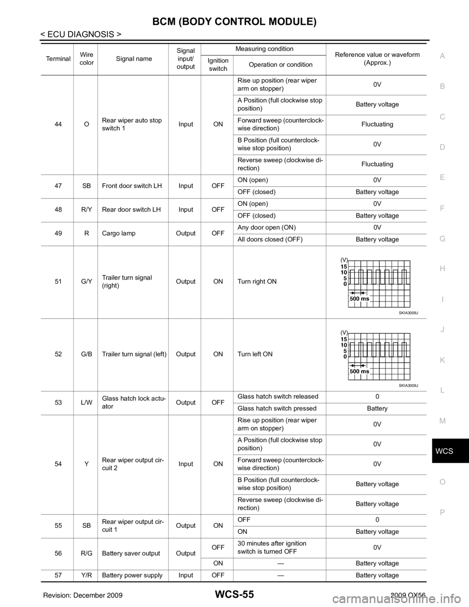
51 G/Y Trailer turn signal
(right) Output ON Turn right ON
52 G/B Trailer turn signal (left) Output ON Turn left ON
53 L/W Glass hatch lock actu-
ator
Output OFFGlass hatch switch released
0
Glass hatch switch pressed Battery
54 Y Rear wiper output cir-
cuit 2 Input ONRise up position (rear wiper
arm on stopper)
0V
A Position (full clockwise stop
position) 0V
Forward sweep (counterclock-
wise direction) 0V
B Position (full counterclock-
wise stop position) Battery voltage
Reverse sweep (clockwise di-
rection) Battery voltage
55 SB Rear wiper output cir-
cuit 1 Output ONOFF
0
ON Battery voltage
56 R/G Battery saver output Output OFF
30 minutes after ignition
switch is turned OFF 0V
ON — Battery voltage
57 Y/R Battery power supply Input OFF —Battery voltage
Te r m i n a l
Wire
color Signal name Signal
input/
output Measuring condition
Reference value or waveform
(Approx.)
Ignition
switch Operation or condition
SKIA3009J
SKIA3009J
Revision: December 20092009 QX56
Page 4033 of 4171
WCS-56
< ECU DIAGNOSIS >
BCM (BODY CONTROL MODULE)
58 W/R Optical sensorInput ONWhen optical sensor is illumi-
nated
3.1V or more
When optical sensor is not illu-
minated 0.6V or less
59 G Front door lock as-
sembly LH actuator
(unlock) Output OFF
OFF (neutral)
0V
ON (unlock) Battery voltage
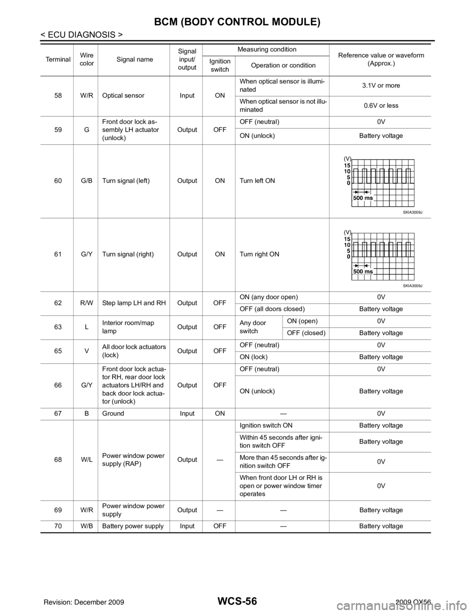
60 G/B Turn signal (left) Output ON Turn left ON
61 G/Y Turn signal (right) Output ON Turn right ON
62 R/W Step lamp LH and RH Output OFF ON (any door open)
0V
OFF (all doors closed) Battery voltage
63 L Interior room/map
lamp Output OFFAny door
switchON (open)
0V
OFF (closed) Battery voltage
65 V All door lock actuators
(lock) Output OFFOFF (neutral)
0V
ON (lock) Battery voltage
66 G/Y Front door lock actua-
tor RH, rear door lock
actuators LH/RH and
back door lock actua-
tor (unlock) Output OFF
OFF (neutral)
0V
ON (unlock) Battery voltage
67 B Ground Input ON—0V
68 W/L Power window power
supply (RAP) Output —Ignition switch ON
Battery voltage
Within 45 seconds after igni-
tion switch OFF Battery voltage
More than 45 seconds after ig-
nition switch OFF 0V
When front door LH or RH is
open or power window timer
operates 0V
69 W/R Power window power
supply
Output —
—Battery voltage
70 W/B Battery power supply Input OFF —Battery voltage
Te r m i n a l
Wire
color Signal name Signal
input/
output Measuring condition
Reference value or waveform
(Approx.)
Ignition
switch Operation or condition
SKIA3009J
SKIA3009J
Revision: December 20092009 QX56
Page 4043 of 4171

WT-1
SUSPENSION
C
DF
G H
I
J
K L
M
SECTION WT
A
B
WT
N
O PCONTENTS
ROAD WHEELS & TIRES
BASIC INSPECTION ....... .............................3
DIAGNOSIS AND REPAIR WORKFLOW ..... .....3
Repair Work Flow ................................................ ......3
INSPECTION AND ADJUSTMENT .....................5
Preliminary Check ............................................... ......5
Transmitter Wake Up Operation ...............................5
ID Registration Procedure .........................................6
FUNCTION DIAGNOSIS ...............................8
TPMS .............................................................. .....8
System Diagram .................................................. ......8
System Description ...................................................8
System Component .................................................10
DIAGNOSIS SYSTEM (BCM) ............................11
CONSULT-III Function (BCM) ............................. ....11
Self-Diagnosis (With CONSULT-III) ........................12
Self-Diagnosis (Without CONSULT-III) ...................13
COMPONENT DIAGNOSIS .........................14
C1708 - C1711 DATA FROM TRANSMITTER
NOT BEING RECEIVED ................................. ....
14
Description .......................................................... ....14
DTC Logic ...............................................................14
Data from Transmitter Not Being Received ............14
Special Repair Requirement ...................................15
C1712 - C1715, C1720 - C1723, C1724 -
C1727 TRANSMITTER MALFUNCTION ....... ....
16
Description .......................................................... ....16
DTC Logic ...............................................................16
Transmitter Malfunction ...........................................16
Special Repair Requirement ...................................17
C1716 - C1719 TRANSMITTER PRESSURE
MALFUNCTION .............................................. ....
18
Description .......................................................... ....18
DTC Logic ...............................................................18
Transmitter Pressure Malfunction ............................18
Special Repair Requirement ................................ ....18
C1729 VEHICLE SPEED SIGNAL ....................19
Description ...............................................................19
DTC Logic ................................................................19
Vehicle Speed Signal ..............................................19
C1735 IGNITION SIGNAL .................................20
Description ...............................................................20
DTC Logic ................................................................20
Diagnosis Procedure ...............................................20
ECU DIAGNOSIS .........................................21
BCM (BODY CONTROL MODULE) .................21
Reference Value .................................................. ....21
Wiring Diagram ........................................................23
Self-Diagnosis (With CONSULT-III) ........................26
Self-Diagnosis (Without CONSULT-III) ...................27
SYMPTOM DIAGNOSIS ..............................29
TPMS .................................................................29
Symptom Table ................................................... ....29
LOW TIRE PRESSURE WARNING LAMP
DOES NOT TURN ON .......................................
30
Low Tire Pressure Warning Lamp Does Not Come
On When Ignition Switch Is Turned On ...................
30
LOW TIRE PRESSURE WARNING LAMP
STAYS ON ........................................................
31
Low Tire Pressure Warning Lamp Stays On When
Ignition Switch Is Turned On ............................... ....
31
LOW TIRE PRESSURE WARNING LAMP
BLINKS .............................................................
32
Low Tire Pressure Warning Lamp Flashes When
Ignition Switch Is Turned On ...................................
32
HAZARD WARNING LAMPS FLASH ..............33
Revision: December 20092009 QX56
Page 4051 of 4171
TPMSWT-9
< FUNCTION DIAGNOSIS >
C
DF
G H
I
J
K L
M A
B
WT
N
O P
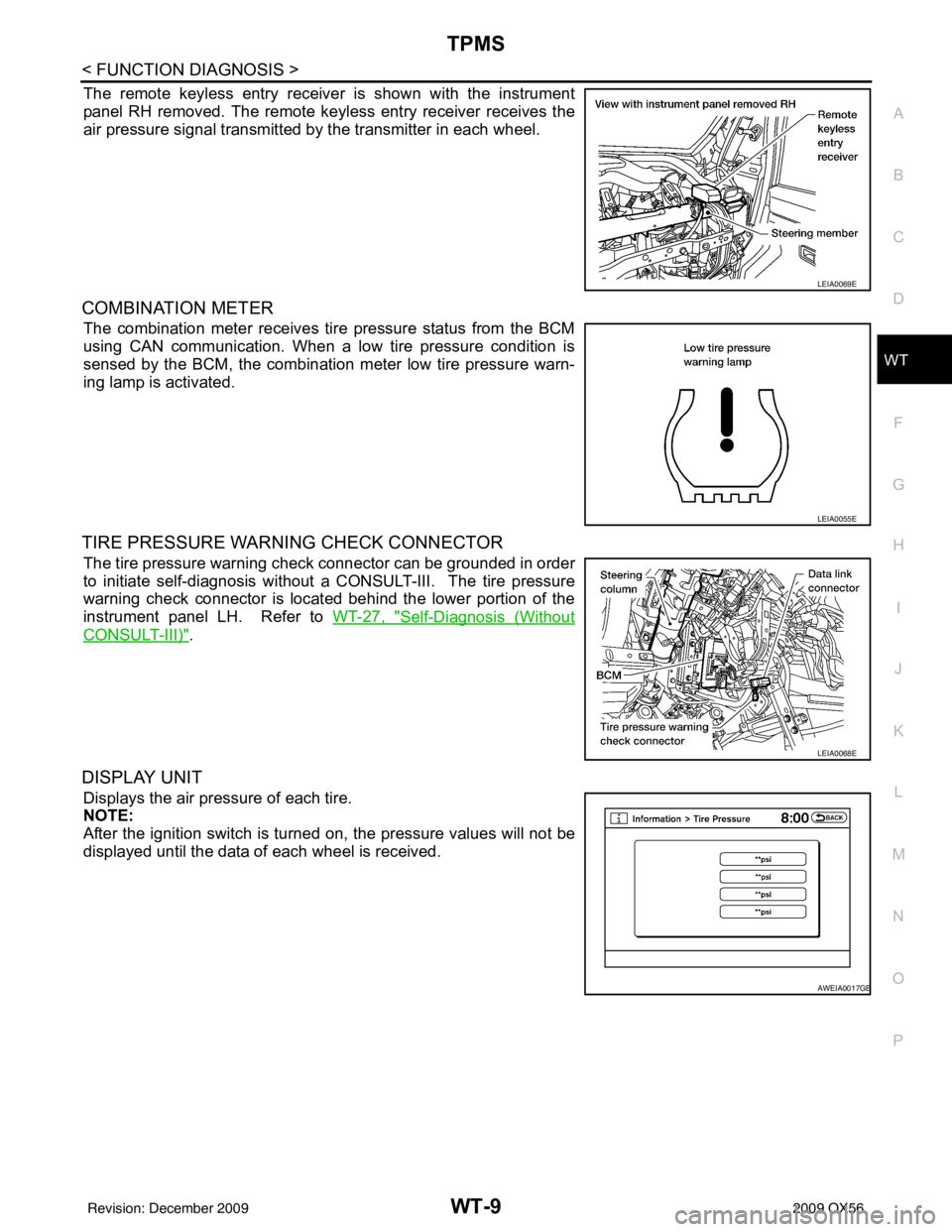
The remote keyless entry receiver is shown with the instrument
panel RH removed. The remote keyless entry receiver receives the
air pressure signal transmitted by the transmitter in each wheel.
COMBINATION METER
The combination meter receives tire pressure status from the BCM
using CAN communication. When a low tire pressure condition is
sensed by the BCM, the combination meter low tire pressure warn-
ing lamp is activated.
TIRE PRESSURE WARNING CHECK CONNECTOR
The tire pressure warning check connector can be grounded in order
to initiate self-diagnosis without a CONSULT-III. The tire pressure
warning check connector is located behind the lower portion of the
instrument panel LH. Refer to WT-27, "
Self-Diagnosis (Without
CONSULT-III)".
DISPLAY UNIT
Displays the air pressure of each tire.
NOTE:
After the ignition switch is turned on, the pressure values will not be
displayed until the data of each wheel is received.
LEIA0069E
LEIA0055E
LEIA0068E
AWEIA0017GB
Revision: December 20092009 QX56
Page 4053 of 4171

DIAGNOSIS SYSTEM (BCM)WT-11
< FUNCTION DIAGNOSIS >
C
DF
G H
I
J
K L
M A
B
WT
N
O P
DIAGNOSIS SYSTEM (BCM)
CONSULT-III Function (BCM)INFOID:0000000003772370
CONSULT-III DIAGNOSTIC MODES
CONSULT-III can display each diagnostic item using the diagnostic test modes shown following.
DESCRIPTION
During driving, the tire pressure monitoring system receives the signal transmitted from the transmitter
installed in each wheel, and turns on the low tire pressure warning lamp when the tire pressure becomes low.
The control unit (BCM) for this system has pr essure judgement and self-diagnosis functions.
FUNCTION
When the tire pressure monitoring system detects low infl ation pressure or an internal malfunction, the low tire
pressure warning lamp in the combination meter comes on. The malfunction is indicated by the low tire pres-
sure warning lamp flashing.
CONSULT-III Application to Ti re Pressure Monitoring System
× : Applicable
– : Not applicable
Data Monitor Mode
Diagnostic mode Description
WORK SUPPORT Supports inspections and adjustments. Commands are transmitted to the BCM
for setting the status suitable for required operation, input/output signals are re-
ceived from the BCM and received data is displayed.
DATA MONITOR Displays BCM input/output data in real time.
ACTIVE TEST Operation of electrical loads can be checked by sending drive signal to them.
SELF-DIAG RESULTS Displays BCM self-diagnosis results.
CAN DIAG SUPPORT MNTR The result of transmit/receive diagnosis of CAN communication can be read.
ECU PART NUMBER BCM part number can be read.
CONFIGURATION Performs BCM configuration read/write functions.
ITEMSELF-DIAGNOSTIC RESULTS DATA MONITOR
Front - Left transmitter ××
Front - Right transmitter ××
Rear - Left transmitter ××
Rear - Right transmitter ××
Warning lamp —×
Vehicle speed ××
CAN Communication ××
MONITORCONDITION SPECIFICATION
VHCL SPEED Drive vehicle. Vehicle speed (km/h or MPH)
AIR PRESS FL
AIR PRESS FR
AIR PRESS RR
AIR PRESS RL • Drive vehicle for a few minutes.
Tire pressure (kPa or psi)
or
• Ignition switch ON and activation tool is transmitting activation signals.
Revision: December 20092009 QX56
Page 4054 of 4171

WT-12
< FUNCTION DIAGNOSIS >
DIAGNOSIS SYSTEM (BCM)
NOTE:
Before performing the self-diagnosis, be sure to register the ID, or the actual malfunction location may be different from that displayed on
CONSULT-III.
Self-Diagnosis (With CONSULT-III)INFOID:0000000003772371
DESCRIPTION
During driving, the tire pressure monitoring system receives the signal trans mitted from the transmitter
installed in each wheel, and turns on the low tire pressure warning lamp when the tire pressure becomes low.
The control unit (BCM) for this system has pressure judgement and self-diagnosis functions.
FUNCTION
When the tire pressure monitoring system detects low inflation pressure or an internal malfunction, the low tire
pressure warning lamp in the combination meter comes on. The malfunction is indicated by the low tire pres-
sure warning lamp flashing.
CONSULT-III Application to Tire Pressure Monitoring System
× : Applicable
– : Not applicable
Data Monitor Mode
NOTE:
Before performing the self-diagnosis, be sure to register the ID, or the actual malfunction location may be different from that displayed on
CONSULT-III. ID REGST FL1
ID REGST FR1
ID REGST RR1
ID REGST RL1
Ignition switch ON ID not registered: YET
ID registered: DONE
WARNING LAMP Low tire pressure
warning lamp on: ON
Low tire pressure warning lamp off: OFF
MONITOR
CONDITION SPECIFICATION
ITEMSELF-DIAGNOSTIC RESULTS DATA MONITOR
Front - Left transmitter ××
Front - Right transmitter ××
Rear - Left transmitter ××
Rear - Right transmitter ××
Warning lamp —×
Vehicle speed ××
CAN Communication ××
MONITORCONDITION SPECIFICATION
VHCL SPEED Drive vehicle. Vehicle speed (km/h or MPH)
AIR PRESS FL
AIR PRESS FR
AIR PRESS RR
AIR PRESS RL • Drive vehicle for a few minutes.
Tire pressure (kPa or psi)
or
• Ignition switch ON and activation tool is transmitting activation signals.
ID REGST FL1
ID REGST FR1
ID REGST RR1
ID REGST RL1 Ignition switch ON ID not registered: YET
ID registered: DONE
WARNING LAMP Low tire pressure
warning lamp on: ON
Low tire pressure warning lamp off: OFF
Revision: December 20092009 QX56
Page 4055 of 4171
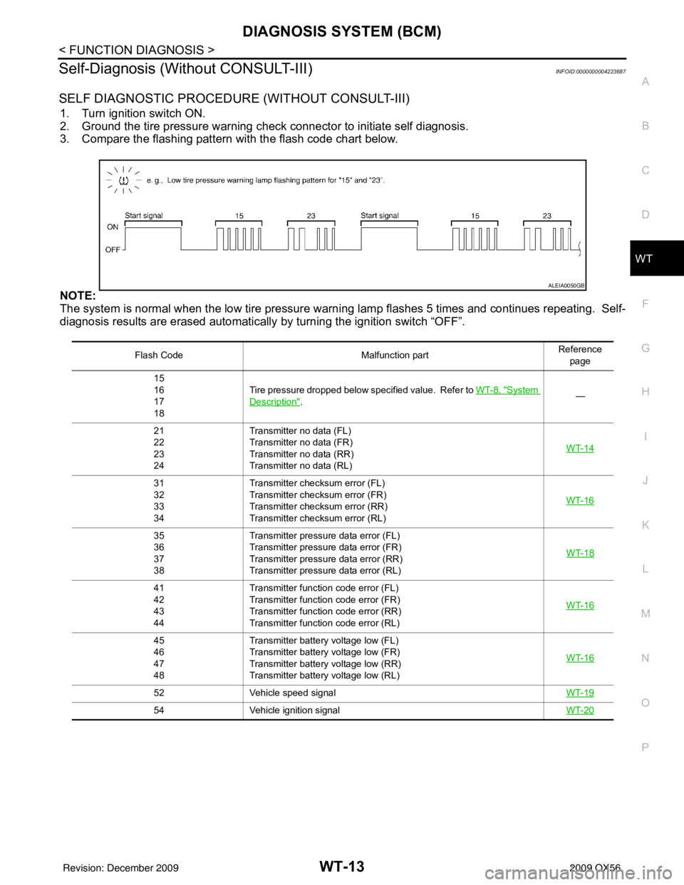
DIAGNOSIS SYSTEM (BCM)WT-13
< FUNCTION DIAGNOSIS >
C
DF
G H
I
J
K L
M A
B
WT
N
O P
Self-Diagnosis (Without CONSULT-III)INFOID:0000000004223687
SELF DIAGNOSTIC PROCE DURE (WITHOUT CONSULT-III)
1. Turn ignition switch ON.
2. Ground the tire pressure warning check connector to initiate self diagnosis.
3. Compare the flashing pattern with the flash code chart below.
NOTE:
The system is normal when the low tire pressure warni ng lamp flashes 5 times and continues repeating. Self-
diagnosis results are erased automatically by turning the ignition switch “OFF”.
Flash Code Malfunction partReference
page
15
16
17
18 Tire pressure dropped below specified value. Refer to
WT-8, "
System
Description". —
21
22
23
24 Transmitter no data (FL)
Transmitter no data (FR)
Transmitter no data (RR)
Transmitter no data (RL)
WT-14
31
32
33
34Transmitter chec
ksum error (FL)
Transmitter chec ksum error (FR)
Transmitter chec ksum error (RR)
Transmitter chec ksum error (RL) WT-16
35
36
37
38Transmitter pressure data error (FL)
Transmitter pressure data error (FR)
Transmitter pressure data error (RR)
Transmitter pressure data error (RL)
WT-18
41
42
43
44Transmitter function
code error (FL)
Transmitter function code error (FR)
Transmitter function code error (RR)
Transmitter function code error (RL) WT-16
45
46
47
48Transmitter battery voltage low (FL)
Transmitter battery voltage low (FR)
Transmitter battery voltage low (RR)
Transmitter battery voltage low (RL)
WT-16
52
Vehicle speed signal WT-19
54Vehicle ignition signal WT-20
ALEIA0050GB
Revision: December 20092009 QX56